

Finite element analysis on stresses field of normalized layer thickness within ceramic coating on aluminized steel
WU Zhen-qiang(����ǿ), XIA Yuan(�� ԭ), LI Guang(�� ��), XU Fang-tao(�췽��)
Institute of Mechanics, Chinese Academy of Sciences, Beijing 100080, China
Received 14 December 2006; accepted 11 June 2007
Abstract:
Multilayer ceramic coatings were fabricated on steel substrate using a combined technique of hot dipping aluminum(HDA) and plasma electrolytic oxidation(PEO). A triangle of normalized layer thickness was created for describing thickness ratios of HDA/PEO coatings. Then, the effect of thickness ratio on stresses field of HDA/PEO coatings subjected to uniform normal contact load was investigated by finite element method. Results show that the surface tensile stress is mainly affected by the thickness ratio of Al layer when the total thickness of coating is unchanged. With the increase of Al layer thickness, the surface tensile stress rises quickly. When Al2O3 layer thickness increases, surface tensile stress is diminished. Meanwhile, the maximum shear stress moves rapidly towards internal part of HDA/PEO coatings. Shear stress at the Al2O3 /Al interface is minimal when Al2O3 layer and Al layer have the same thickness.
Key words:
normalized layer thickness; multilayer coatings; interfacial stresses; finite element method(FEM);
1 Introduction
Plasma electrolytic oxidation(PEO) is a new technology of fabricating ceramic coatings on valve metals such as Al, Mg, Ti and Nb[1-4]. Recently, many combined PEO techniques are used in forming ceramic coatings on steel substrate, such as thermal spraying/ micro-arc oxidation[5], plasma sputtering/microarc oxidation[6], hot dipping aluminum/plasma electrolytic oxidation(HDA/PEO)[7-8]. Here, they are all called ��ceramic coating on aluminized steel��. Earlier researches showed that the cross-sectional structure of HDA/PEO has multilayers. Outer ceramic layer is mainly composed of ��-, ��-, ��-Al2O3 and Al-Si-O amorphous phases, and its hardness is about Hv1500[7-8]. It is well known that PEO ceramic coatings can greatly improve the wear- resistance, anti-corrosion and heat-resisting performances of substrates.
HDA/PEO coatings are different from gradient coatings for possessing a lower hardness aluminum layer between ceramic coating and FeAl intermetallic layer. So it really lacks a new method to design these multilayer coatings and also to optimize them. Therefore, it is very important to describe the thickness relationship accurately and to optimize these layered structures.
Finite element method(FEM) has been applied successfully in failure analysis, optimum design and stresses analysis about coating system[9-15]. In this study, the FEM model of homogeneous layers is adopted for HDA/PEO coatings. Pores, process-induced microcracks, and residual stresses in PEO coatings are not taken into account. Stresses in multilayer coatings subjected to uniform normal contact load were calculated by using standard FEM software. Influences of thickness ratios on stresses at the surface and interfaces were also investigated. The results can provide important evidences for optimum design and failure analysis of HDA/PEO coatings.
2 Triangle of normalized layer thickness
As shown in Fig.1(a), HDA/PEO composite coating has multilayer structures and mainly consists of FeAl layer, Al layer and Al2O3 layer. According to the cross- sectional structure, the coating thickness model is established (Fig.1(b)). Surface and interfaces are named respectively: Surface, Interface 1(Al2O3/Al), Interface 2 (Al/FeAl) and Interface 3 (FeAl/Substrate). Here, ��, �� and �� are the normalized layer thickness of Al2O3 layer,
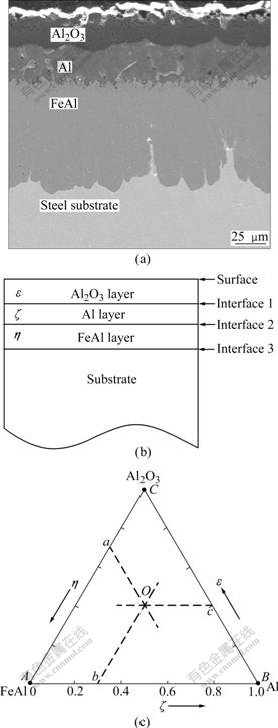
Fig.1 Creation of triangle of normalized layer thickness: (a) Cross-sectional structure of HDA/PEO; (b) Thickness model; (c) Equilateral triangle
Al layer and FeAl layer, respectively. The relation of these thickness ratios is given as
��+��+��=1 (1)
One equilateral triangle ABC is utilized to describe the thickness relations of HDA/PEO coatings, which is called the triangle of normalized layer thickness, as shown in Fig.1(c). Any point in this triangle represents one kind of thickness system of HDA/PEO, e.g. point O.
As shown in Fig.2, the triangle of normalized layer thickness can be divided into four zones by three lines connected with middle points. The important characteristic of zone Z1-Z3 is that the thickness of one layer exceeds half of the total thickness of coating. For example, Z1 is the zone where FeAl layer thickness is dominant. Z4 is the particular zone where every layer thickness is approximately equal. But, one or two layers are degenerated at boundaries of the triangle ABC.
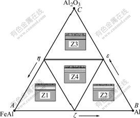
Fig.2 Zone division in triangle of normalized layer thickness
3 FEM model of HDA/PEO coating
3.1 Creation of FEM model
Forty-five different thickness systems of HDA/PEO coatings are chosen for FEM analyses. The ANSYS finite element package is used to create FEM models of every thickness system. For any thickness system of HDA/PEO, the maximal surface stress is specified as the surface stress of normalized layer thickness and the maximal interface stress is specified as the interface stress of normalized layer thickness.
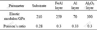
The FEM model of HDA/PEO coating is created with respect to plane strain assumption. Contact pressure distribution is shown in Fig.3(a), where p0 is uniform pressure, a is 1/2 of contact radius, and the total thickness of coating is 100 ��m. Fig.3(b) shows the distribution of FEM meshes. The length and width of FEM model are 30a and 20a. To improve the accuracy of calculation, meshes under contact region are refined and the total number of FEM meshes is 73 000, as shown in Fig.3(c). Boundary BC is applied constraint on X and Y orientation, while boundaries AB and CD are free boundaries. Since elastic mechanical computation is mainly investigated in this study, p0 is 100 MPa and a is 250 ��m. Settings of other parameters of FEM model are listed in Table 1.
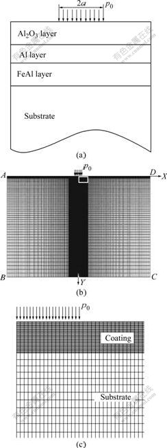
Fig.3 FEM model of HDA/PEO coating: (a) Uniform contact pressure; (b) FEM meshes; (c) Magnified image of local meshes
Table 1 Parameters of multilayer coating FEM model
3.2 Testing of FEM model
In order to check the accuracy of boundary conditions and the finite element meshes used in the present model, the FEM results are compared with analytical solutions. With the assumption of plane strain, analytical results of stress field of an elastically homogeneous half-space subjected to uniform pressure has been given in Ref.[15]. Here, the sizes of HDA/PEO FEM model are much larger than contact radius. And when coatings and substrate are set with the same parameters, FEM model can be considered approximately as an elastically homogeneous half-space solid. It can be seen from Fig.4 that there is a consistency between FEM and analytical solution. This means that the FEM model gives reliable values of stresses.
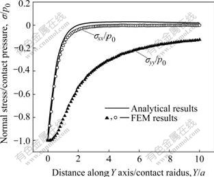
Fig.4 Analytical and FEM solutions for stresses along Y axis
4 Results and discussion
It has been found that the life of ceramic coatings is related to crack or fracture in tribological and wear situations[12-14]. Crack is caused by the stresses arising at the interface, while fracture is resulted from high stresses within the coating or at the surface. In addition, just because the compressive strength of brittle ceramic coating is much higher than its tensile strength, the cracks often occur at the surface in case of surface tensile stress exceeding tensile strength. So the stresses at the surface and the interfaces are mainly investigated.
4.1 Surface tensile stress(STS)
Under the same load conditions, the maximal surface tensile stress(STS) of every coating with different thickness ratio was drawn in the triangle of normalized layer thickness, as shown in Fig.5. The maximal magnitude of STS ��xx often occurs at zone Z2 and near the boundary BC and point B. Its value is about 41.1 MPa. Values of tensile stresses near the boundaries AC or AE is about 10 MPa, which are relatively small.
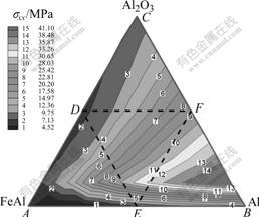
Fig.5 Distribution of maximal STS ��xx in triangle
Contour distribution in Fig.5 is approximately parallel to the boundary AC. This expresses that STS ��xx increases quickly along the direction from AC to the point B, i.e. the increasing direction of the Al layer thickness. It is concluded that STS ��xx is greatly affected by aluminum thickness. The reason is that aluminum layer cannot provide enough support for ceramic layer, and when Al layer thickness is high, ceramic layer deforms easily. However, surface tensile stresses are slightly affected by the thickness of FeAl layer or Al2O3 layer when the thickness of Al layer is fixed.
Fig.6 shows the influence of other layers on tensile stresses with the change of Al thickness. Curve 1 shows the effect of thickness ratio �� of FeAl layer on tensile stresses when the thickness of Al2O3 layer is a constant (0.125). Tensile stress at the surface is reduced quickly as thickness ratio �� increases because the thickness ratio of Al layer simultaneously decreases. Curve 2 shows the effect of thickness ratio �� of Al2O3 layer on tensile stresses when the ratio of FeAl layer is a constant (0.125). It can be seen that tensile stress can also be minimized with the increase of the thickness ratio ��.
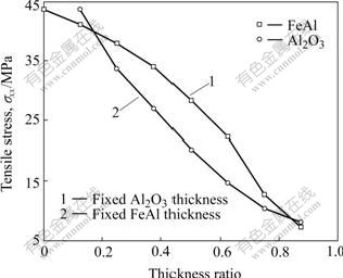
Fig.6 Effect of FeAl or Al2O3 layer on STS ��xx
4.2 Maximal shear stress within coatings
The magnitude of maximal shear stress within coatings varies in a narrow range of 30-40 MPa when the thickness ratios of coatings are changed, as shown in Fig.7. The maximal shear stress in the triangle of normalized layer thickness locates near point F when Al2O3 and Al layers have the same thickness.
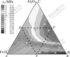
Fig.7 Distribution of maximal shear stress ��xy
It is clear that normalized layer thickness has more influence on the distance of maximum shear stress from the surface than on its magnitude through comparing Fig.7 and Fig.8. This shows that Al2O3 thickness is a key factor affecting the location of the maximal shear stress within coatings.( The main cause is that the maximum shear stress often occurs near the middle of Al2O3 layer. So the maximum shear stress moves towards internal part as the thickness of ceramic layer increases.
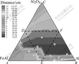
Fig.8 Distance of maximal ��xy from surface
4.3 Distributions of interfacial shear stress
Some coating thickness systems, locating at top of the triangle of normalized layer thickness, have only single coating/substrate interface, so it is specified that shear stresses at interface 1-3 have the same magnitude of shear tresses. Since the coating thickness systems at boundaries have two interfaces (internal, external), it is specified that shear stresses at Al2O3/Al interface or Al/FeAl interface equal shear stresses at external interface. Shear stresses at FeAl/Substrate interface equal shear stresses at internal interface.
Variations of the maximum shear stresses at interfaces in the triangle of normalized layer thickness are illustrated in Figs.9-11. Interfacial shear stress ��xy near boundary AC is high, while it is low near point B. This indicates that increasing thickness of Al layer can reduce shear stresses at the interfaces.
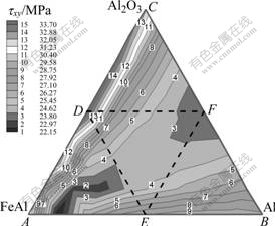
Fig.9 Distribution of maximal shear stress ��xy at Al2O3/Al interface
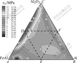
Fig.10 Distribution of maximal shear stress ��xy at Al/FeAl interface
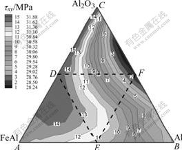
Fig.11 Distribution of maximal shear stress ��xy at FeAl/Substrate interface
As shown in Fig.9, shear stresses at Al2O3/Al interface are affected greatly by the thickness ratio of Al2O3 layer to Al layer. The minimal value of shear stress at Al2O3/Al interface is about 22.1 MPa when Al2O3 layer and Al layer have the same thickness, which occurs near line AF. Shear stress arises when coating thickness system is away from line AF. The maximal shear stress is about 32.8 MPa, which occurs at the boundary AC. Nevertheless, shear stress at Al2O3/Al interface is affected little by the FeAl layer thickness.
As shown in Fig.10, the shear stress at Al/FeAl interface has close relations with the layer thickness of both FeAl and Al2O3. Its magnitude is between shear stress at Al2O3/Al interface and that at FeAl/Substrate interface.
Shear stress at FeAl/Substrate interface varies in a relatively narrow range from 28.2 to 31.9 MPa, as illustrated in Fig.11. The maximum lies at boundary AC and the minimum lies in the middle of boundary BC. Shear stress arises little when the thickness of FeAl layer increases. Therefore, the FeAl/Substrate interfacial shear stresses in zone Z1 are higher than those in other zones owing to the thick FeAl layer.
In summary, every layer of HDA/PEO coatings plays an important functional role in layered structure when the coatings are subjected to uniform pressure. For example, Al2O3 layer controls the location of the maximum shear stress within coating and can improve the support of coatings. The advantage of Al layer is that interfacial stresses can be reduced greatly. On the contrary, the FeAl layer affects slightly the stresses at the surface and interfaces. The better the distribution of stress at surface and interfaces is, the more excellent the properties of composite coatings are gained, when thicker ceramic layer and thinner Al layer are chosen.
5 Conclusions
1) The thickness relations among layers of HDA/PEO coatings are described by the triangle of normalized layer thickness efficiently and easily.
2) Surface tensile stress(STS) is mainly affected by the thickness ratio of Al layer. With increasing Al layer thickness, STS arises. Especially, STS can be reduced by the increase of the thickness ratio of Al2O3 layer (or FeAl layer) when thickness ratio of FeAl layer (or Al2O3 layer) is fixed.
3) The maximum of shear stress is hardly changed by thickness��ratio relations. However, the maximum shear stress moves quickly towards external parts of coatings with increasing thickness ratio of Al2O3 layer.
4) Shear stresses at Al2O3/Al interface can be lessened greatly by Al layer. Shear stress at FeAl/ Substrate interface is slightly changed by normalized layer thickness.
References
[1] YEROKHIN A L, NIE X, LEYLAND A, MATTHEWS A, DOWEY S J. Plasma electrolysis for surface engineering [J]. Surf Coat Technol, 1999, 122: 73-93.
[2] GUAN Yong-jun, XIA Yuan. Correlation between discharging property and coatings microstructure during plasma electrolytic oxidation [J]. Trans Nonferrous Met Soc China, 2006, 16(5): 1097-1102.
[3] CURRAN J A, CLYNE T W. Porosity in plasma electrolytic oxide coatings [J]. Acta Materialia, 2006, 54(7): 1985-1993.
[4] KHAN R H U, YEROKHIN A L, PILKINGTON T, LEYLAND A, MATTHEWS A. Residual stresses in plasma electrolytic oxidation coatings on Al alloy produced by pulsed unipolar current [J]. Surf Coat Technol, 2005, 200(5/6): 1580-1586.
[5] GU Wei-chao, SHEN De-jiu, WANG Yu-lin, CHEN Guang-liang, FENG Wen-ran, ZHANG Gu-ling, FAN Song-hua, LIU Chi-zi, YANG Si-ze. Deposition of duplex Al2O3/aluminum coatings on steel using a combined technique of arc spraying and plasma electrolytic oxidation [J]. Applied Surface Science, 2006, 252(8): 2927-2932.
[6] EFREMOV A P. Composite coating for protecting carbon steel stress corrosion failure [J]. Protection of Metals, 1989, 25: 176-180.
[7] YU Sheng-xue, XIA Yuan, CHEN Ling, GUAN Yong-jun, YAO Mei. Formation and structure of composite coating of HDA and micro-plasma oxidation on A3 Steel [J]. Trans Nonferrous Met Soc China, 2004, 14(Suppl.2): 310-314.
[8] XIE Shi-yue, WANG Cong-zeng, SHU Xue-kuan, MA Jie. Research of Hot-dip aluminum and micro arc oxidation on surface of carbon steel [J]. Light Alloy Fabrication Technology, 2003, 31(9): 35-38. (in Chinese)
[9] UHLMANN E, KLEIN K. Stress design in hard coatings [J]. Surf Coat Technol, 2000, 131: 448-451.
[10] BENNANI H H, TAKADOUM J. Finite element model of elastic stress in thin coatings submitted to applied forces [J]. Surf Coat Technol, 1999, 111: 80-85.
[11] DJABELLA H. Finite element comparative study of elastic stresses in single, double layer and mulitlayered coated systems [J]. Thin Solid Film, 1993, 235: 156-162.
[12] FAGAN M J, PARK S, WANG L. Finite element analysis of the contact stresses in diamond coatings subjected to a uniform normal load [J]. Diamond Relat Mater, 2000, 9(1): 26-36.
[13] DJABELLA H, AMNELL R D. Finite element analysis of contact stresses in an elastic coating on an elastic substrate [J]. Thin Solid Film, 1992, 213: 205-219.
[14] BANSAL P, SHIPWAY P H, LEEN S B. Finite element modeling of the fracture behavior of brittle coatings [J]. Surf Coat Technol, 20065, 200: 5318-5327.
[15] JOHNSON K L. Contact mechanics [M]. Cambridge: Cambridge University Press, 1992: 21-26.
Foundation item: Project(10572141) supported by the National Natural Science Foundation of China
Corresponding author: XIA Yuan; Tel: +86-10-62554190; E-mail: xia@imech.ac.cn
(Edited by YANG Bing)
