

Fabrication of conventional and nanostructured NiCrC coatings via HVAF technique
TAO Kai(�� ��)1, ZHANG Jie(�� ��)1, CUI Hua(�� ��)2,
ZHOU Xiang-lin(������)1, ZHANG Ji-shan(�ż�ɽ)1
1. State Key Laboratory for Advanced Metals and Materials,
University of Science and Technology Beijing, Beijing 100083, China;
2. School of Materials Science and Engineering, University of Science and Technology Beijing,
Beijing 100083, China
Received 11 May 2007; accepted 24 September 2007
Abstract:
The conventional and nanostructured NiCrC (with chemical composition of 80%NiCr-20%CrC) coatings with high quality were fabricated via high velocity air-fuel(HVAF) spraying technique. The microstructures of these coatings were characterized by means of metallographic microscopy, scanning electron microscopy, transmission electron microscopy and X-ray diffractometry. A Vickers microhardness tester was used to determine the mechanical properties of the as-sprayed coatings. The single-line approximation(SLA) method was employed to calculate the grain size and microstrain of as-sprayed nanostructured coating based on the XRD data. The results show that nanostructured NiCrC coating possesses a more uniform and denser microstructure, much higher microhardness and better fracture toughness than its conventional counterpart. Both TEM observation and calculation results based on XRD profile show that as-sprayed nanostructured NiCrC coating has a homogeneous nanocrystalline microstructure with an average grain size of 40 nm.
Key words:
HVAF spraying; nanostructure; coating; NiCrC; properties;
1 Introduction
Thermally sprayed coatings have been increasingly applied in various industry fields to provide protection against wear, erosion and corrosion[1-2]. The spraying process usually involves the deposition of molten or semi-molten droplets of powder onto a substrate to form a coating. Recently, cold spraying, during which heated and softened solid particles are accelerated and deposited onto the substrate to form coatings with excellent properties, has attracted great interests from researchers, and is also affiliated to the thermal spray field[3-4]. It is a common knowledge today that high velocity oxy-fuel (HVOF) systems are capable of producing better metal, alloy and carbide-metal cermet coatings with high density, high hardness, superior bond strength and less decarburization than many of the other thermal spraying methods[5]. However, there are yet unsatisfied aspects, like the oxygen content, economic cost and relatively low deposition efficiency.
High velocity air-fuel(HVAF) spraying is a recently developed technology for deposition of metallic and carbide-metal coatings of commercial powder materials[6-8]. The specificity of the process is that sprayed powder particles are heated below their melting point, meanwhile, accelerated to velocity well above 700 m/s to form dense and non-oxidized deposits with minimal thermal deterioration and outstanding technology efficiency. Thus, this is a solid particle spraying technology where particle temperature remains an important factor of coating formation. The process can be described as ��warm kinetic spraying��, positioned between family of HVOF spraying process and Cold Gas-Dynamic Spraying[7]. During the spraying process, HVAF gun combusts a mixture of compressed air and fuel gas (propane, propane-butane, propylene or MAPP-gas) in combustion chamber, generating high velocity jet of combustion products exhausting out of the nozzle. Using compressed air as oxidant plays an important role in saving cost of spraying process. The absence of spray material fusion, proper temperature for deposition and high impact velocities are distinguished characteristics of the HVAF coating deposition process.
Carbide-based cermets including tungsten carbide (WC) and chromium carbide (CrC) cermets are commonly used for wear resistant coatings. For high temperature applications requiring wear resistance, thermally sprayed chromium carbide-nickel chromium (CrxCy-NiCr) coatings are employed in light of the excellent corrosion resistance and reasonable wear resistance of chromium carbides at temperature up to 900 ��. Such materials are also employed in low temperature corrosive service, where they again provide wear and corrosion protection[9].
Nanostructured materials are usually characterized by a microstructural length scale in 1-100 nm regime. More than 50% (volume fraction) of atoms are associated with grain boundaries or interfacial boundaries when the grain is small enough. Thus, a significant amount of interfacial component between neighboring atoms associated with grain boundaries contributes to the physical properties of nanostructured materials. Using nanostructured feedstock powders, thermal spraying has allowed researchers to generate coatings possessing higher hardness, strength, toughness, corrosion and wear resistance than the conventional counterparts[10].
This work aims at presenting the synthesis process of conventional and nanostructured NiCrC alloy coatings, and their corresponding microstructure characteristics and mechanical properties.
2 Experimental
2.1 Materials
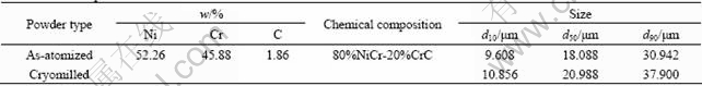
Two types of NiCrC powders, namely as-atomized powders with a conventional coarse grain structure and cryomilled powders with a nanostructure, were employed as HVAF feedstock materials in this study. The former was prepared using gas atomization method with a circumferential seam atomizer. The latter was synthesized using cryomilling method. The detailed data were presented elsewhere. Specifications of both the powders are listed in Table 1. Both the powders were deposited by HVAF spraying onto medium steel substrates with dimension of 50 mm��12 mm��8 mm. Substrates were degreased using acetone, and then roughened by grit blasting with brown alumina in 90 ��m particle size just prior to coating.
Table 1 Nominal powder characteristics
2.2 HVAF spraying
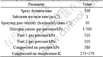
An Intelli-Jet Activated Combustion High Velocity Air-Fuel (AC-HVAF) spraying system of UniqueCoat technologies was used to deposit the coatings onto medium steel coupons under a range of spray conditions. The coupons had been grit blasted for a period of 30 s with alumina using compressed air at a pressure of 1 MPa. In this work, propane was used as fuel gas with nitrogen as powder carrier gas. The spray parameters were identical for both coatings and are listed in Table 2. The coupons were mounted on the circumference of a turntable, which had a horizontal axis of rotation to give an effective vertical traverse rate across the spray pass at a velocity of 1 m/s. The AC-HVAF spraying gun was placed in front of the coupons at a stand-off distance of 150 mm to give a horizontal spray jet and scanned horizontally at 0.01 m/s. Both coatings were the result of 12 passes of the torch with nominally the same powder feed rate.
Table 2 Spraying parameters employed for coating deposition
2.3 Microstructural characterization and mechanical testing
Cross-sectional samples of the coatings were investigated using a LEICA DMR metallographic microscope and a ZEISS SUPPA 55 scanning electron microscope in back scattered electron imaging mode. A detailed microstructure of the as-deposited nanostructure NiCrC coating was revealed utilizing a HITACHI H-800 transmission electron microscope with acceleration voltage of 200 kV. TEM disc-shape specimen of the nanostructured coating was prepared by ion-beam thinning at a current of 0.5 mA and an inclination angle of 12?. Microhardness and fracture toughness tests were performed on a LEICA VMHT 30M machine using a 3 and a 10 N load respectively with dwell time of 15 s. X-ray diffractometry(XRD) of as-sprayed coatings was performed on a PHILIPS APD-10 diffractometer equipped with a graphite monochromator with Cu K�� radiation (0.154 06 nm) using a 0.02? step size. After the effects of K��2 were corrected, the profile data, like peak positions and full width at half maximum, of XRD reflections were computed using a software package in the diffractometer. In the present work, the pure nickel powder after annealing was selected as a standard sample for the determination of instrumental broadening. The computation of grain size and microstrain based on XRD analysis was conducted by single-line approximation (SLA) method[10].
3 Results
3.1 Microstructure of coatings
Fig.1 shows the metallographic images of cross- sectional microstructure of the two as-sprayed coatings. Both coatings exhibited a compact and homogeneous structure. The porosity of coating was analyzed from at least five metallographic images with the corresponding software. And the results were 1.36% for the conventional coating and 1.02% for the nanostructured coating, as listed in Table 3, indicating that as-sprayed nanostructured coating had a denser structure. SEM back scattered images of the coatings are revealed in Fig.2. The microstructures of two coatings differed much from each other. For conventional NiCrC coating, some powders were heated to a relatively high temperature during spraying or even with fusion occurring, and this would lead to the splat-like morphology. However, there were large quantities of powders which had not been melted or possessed relatively low temperature and consequently these ones had retained much of their original shape upon deposition, as seen in Fig.2(a). With the EDS analysis, chromium carbide which exhibited dark in the image was labeled by arrow as region C. According to the XRD analysis result, all the chromium carbides are in the form of Cr7C3. Oxides can be observed from the microstructure at the splat boundaries which were easily identified. In addition, porosity is also labeled as region P in Fig.2(a). The nanostructured coating, which was fabricated from NiCrC powders cryomilled for 20 h, revealed a very dense and homogeneous microstructure although a small amount of porosity was also observed and was labeled as region P in Fig.2(b). Very fine chromium carbide is homogeneously distributed in the NiCr matrix, and even the carbide phase in large portion of this material is hard to discern. A typical lamellar structure characteristic could be seen in the image, but no splat boundary could be identified.
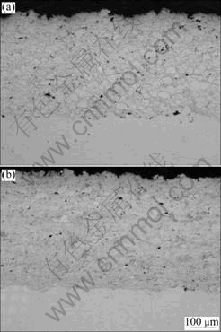
Fig.1 Metallographic images of cross-sectional microstructure of NiCrC coating: (a) Conventional; (b) Nanostructured
Table 3 Properties of as-sprayed conventional and nano- structured NiCrC coating
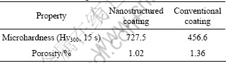
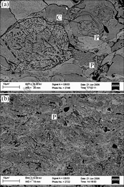
Fig.2 SEM-back scattered images showing cross-sectional microstructure: (a) As-sprayed conventional NiCrC coating; (b) As-sprayed nanostructured NiCrC coating
3.2 XRD pattern
The phase analysis of conventional and nanostructured NiCrC coatings was determined by XRD. Phase constitution of both coatings consisted of NiCr solid solution, Cr7C3 and Cr2O3. Fig.3 shows the XRD pattern of as-deposited nanostructured NiCrC coating. Because the NiCr phase took 80% of the chemical composition, the outstanding phase of the coating was NiCr solid solution. Cr7C3 as demarked in Fig.3 was preserved from the feedstock powders during the HVAF spraying process. Cr2O3 as the only oxide phase was also determined in XRD pattern of both coatings. For nanostructured coating, the peaks from Cr2O3 looked slightly stronger compared with corresponding as-milled powders. The increase in oxide content was believed to generate from the oxidation reaction of Cr in the NiCr solid solution or the chromium carbide with oxygen during the thermal spraying. No phase transformation occurred during the spraying, which was attributed to the high thermal stability of chromium carbide or relatively low temperature of the flame jet.
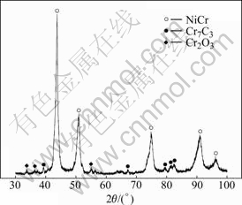
Fig.3 XRD pattern of as-sprayed nanostructured NiCrC coating
3.3 Mechanical properties of as-sprayed coatings
The microhardness values were measured from the interface between substrate and coating towards both directions perpendicular to the interface at an interval of 100 ��m. Each individual result was the average value of at least 5 values obtained from the same horizontal plane. The microhardness value distribution and average value of both coating samples are shown in Fig.4 and Table 3 respectively. As shown in Fig.4, both coatings had a uniform distribution of hardness along the measured direction, which also accounted for the homogeneous characteristic of the microstructure. The average hardness value was 456.6 (Hv300, 15 s) for conventional coating and 727.5 (Hv300, 15 s) for nanostructured coating, as listed in Table 3. For the substrate, there was a slight increase of hardness value in the region close to the interface as shown in Fig.4, which was considered as a result of the deformation hardening effect caused by serious impingement of the flying particles against the substrate during deposition.
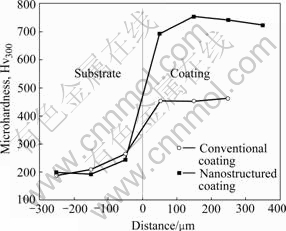
Fig.4 Microhardness results of HVAF-sprayed conventional and nanostructured NiCrC coatings
The abrasion resistance of thermal sprayed coatings is related to the relative fracture toughness. The indentation fracture method is often employed to characterize the relative fracture toughness of coatings [11]. An indentation fracture examination was performed on both conventional and nanostructured NiCrC coatings and some of the results are shown in Figs.5(a) and (b). Under the same load, indentation marks in the nanostructured coating were smaller than those in the conventional coating because nanostructure provided the coating with a higher hardness as described previously. Under a load of 5 N, no crack was found in either of the two coatings, and both coatings kept their integrity well. When the load was increased to 10 N, a slight crack along splat boundary was observed in the conventional coating sample caused by the indentation, and is indicated in Fig.5(a) labeled as region C. Whereas no trace of cracking was present in the nanostructured coating. These results suggested that both coatings had good fracture toughness, especially for the nanostructured coating which possessed higher fracture toughness relative to that of the conventional one.
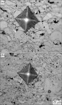
Fig.5 Indentation fracture morphologies on as-sprayed NiCrC coatings: (a) Conventional coating using 10 N load; (b) Nano- structured coating using 10 N load
3.4 TEM images of as-sprayed nanostructured coating
TEM analysis was conducted to give detailed information of the nanostructured coating. Fig.6 shows the bright field image and the corresponding diffraction pattern of nanostructured NiCrC coating. As depicted in Fig.6(a), nanostructured NiCrC coating had a uniform and nanoscale microstructure with most of the grain appearing equiaxed. The grain size measured in the TEM observation ranged from 22.03 to 82.22 nm, and the average value was 42.51 nm. The consistent distribution of grain size also indicated that the nanostructure characteristic of both metal matrix and chromium carbide was successfully preserved during the HVAF spraying process from the cryomilled powders. As shown in Fig.6(b), the corresponding diffraction pattern was typical polycrystal rings, and was determined as characteristic diffractions from crystallographic planes corresponding to NiCr solid solution, Cr7C3 and Cr2O3 respectively. The phase identification from TEM diffraction pattern was consistent well to the results in the XRD analysis.
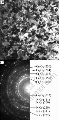
Fig.6 TEM images of as-sprayed nanostructured NiCrC coating: (a) Bright field image; (b) Diffraction pattern
3.5 Determination of grain size for nanostructured coating by XRD
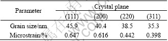
When studying nanostructured (nanocrystalline) materials, TEM is characterized by its direct imaging and information representing only a local region, while XRD is noted for its simplicity in sample preparation and structural information regarding mean grain size and microstrain in the entire sample. Based on the data from XRD profile, single-line approximation(SLA) method was employed to calculate the grain size and microstrain in each individual crystallographic orientation. The calculated results from each XRD peak were different, as presented in Table 4, ranging from 35.3 to 45.9 nm, which well corresponds to the situation observed in TEM images as shown in Fig.6(a). This consistence in turn proved the uniform microstructure of as-sprayed nanostructured NiCrC coating. The microstrain values in different crystallographic orientations varied from each other as listed in Table 4, having a tendency of decreasing with the reducing of corresponding mean grain size.
Table 4 Grain size and microstrain in individual crystallographic orientation for nanostructured NiCrC coating
4 Discussion
4.1 Chromium carbide in NiCrC materials
The thermally stable forms of chromium carbide include Cr3C2, Cr7C3 and Cr23C6. Of these three, Cr3C2 is the most common used, but is relatively more active and tends to decarburize and transfer to the other two forms during long time service at high temperature; whereas Cr23C6 is the finally equilibrium phase[12]. This phenomenon can be explained in terms of thermal dynamic theories. The possible reactions and their accompanying Gibbs free energy changes are listed in Eqns.(1)-(3). The equations for computing Gibbs free energy were deduced using Gibbs free energy function method (�� method):
3Cr+2C��Cr3C2
?G1/(J?mol-1)=-88 890.3-16.003T (298-1 600 K)
��1=0.993 3 (1)
7Cr+3C��Cr7C3
?G2/(J?mol-1)=-156 447-35.158T (298-1 500 K)
��2=0.998 1 (2)
23Cr+6C��Cr23C6
?G3/(J?mol-1)=-384 535-64.476T (298-1 800 K)
��3=0.998 0 (3)
where �� is the certainty factor with 1 as the maximum value. The data used for calculating ?G for reactions (1)-(3) were from Ref.[13]. It is clear that reaction (3) has the smallest value of Gibbs free energy change. Accordingly Cr23C6 exhibits the highest thermal stability.
According to the data in Ni-Cr binary phase diagram, when the C content in this alloy was larger than 4.5% and with a melting temperature higher than (1 576��10) ��, did the Cr7C3 phase like to form. Considering the chemical analysis result of 1.86% for C content, it was supposed that a heterogeneous distribution of C element happened in the alloy when melting proceeded before atomizing. The so-calculated proportions of NiCr and Cr7C3 in the NiCrC alloy were 80% and 20%, respectively, as listed in Table 1.
4.2 HVAF sprayed conventional and nanostructured coatings
HVAF spraying is a new thermal spray technology created for quick, simple and inexpensive application of high quality coatings, which are able to meet or exceed industry standards for hardness, density, bond strength and oxide content, as well as wear, corrosion and fatigue resistance[6]. As depicted in Figs.1(a) and (b), both HVAF sprayed conventional and nanostructured coating possessed a uniform and dense microstructure with very low porosity. During the HVAF spraying process, feedstock particles can be accelerated to velocities exceeding 700 m/s, while particle temperature remains slightly below the melting point of the metal or metallic binders, allowing HVAF to operate in ��solid-particle�� spray mode. For comparison, HVOF coatings are generally thought to form from the molten or semi-molten particles. When fabricating cermet coating with carbides, the high temperature usually causes the decarburization of carbide phase, and leads to the reducing in coating quality. This disadvantage becomes more serious when it comes to nanostructured cermet materials[14]. In addition, the deposited particles do not bond together properly due to solidification shrinkage and oxide scale, which results in defects in the form of voids and other imperfections. Meanwhile, HVAF coating has the potential of not presenting such deterioration or imperfections, in which all of carbide phases are well preserved and the particles are tightly bonded together. This was well demonstrated in Figs.2(a) and (b). As shown in Fig.2(a), most feedstock powders retained their original microstructure with various extents of deformation on shape, and only very thin oxide scale could be observed along the splat boundaries. These seemed to testify the ��solid-particle�� spray mode of HVAF process, during which solid particles were far less susceptible to oxidation than molten or semi-molten HVOF particles. The morphology of nanostructured NiCrC coating was radically different from that of the conventional coating. As seen from Fig.2(b), an extremely homogeneous microstructure was revealed for the nanostructured coating, where metallic matrix and very fine chromium carbide were uniformly distributed, with splat boundary rarely presenting.
Based on the results of XRD and TEM results, no thermal deterioration of carbides happened during the HVAF spraying process. All the carbides existed in the form of Cr7C3, same to that of cryomilled powders. The only visible change was a slight increase in the amount of chromium oxide (in the form of Cr2O3), which was easy to form during thermal exposure of the feedstock powders. It was believed that perfect preservation of carbide yields premium wear resistance, and the presence of a proper amount of oxide contributes much to the high thermal stability of nanostructured materials[15-16], which has been well proved in our following experimental work presented elsewhere.
4.3 Mechanical properties of HVAF sprayed coatings
Microhardness and fracture toughness are two important properties for thermal sprayed coatings. High hardness combined with good toughness is believed to provide coatings with excellent wear resistance in most cases. Compared with the mechanical properties reported in related literature[17], both HVAF sprayed conventional and nanostructured NiCrC coatings exhibited high microhardness with good fracture toughness, as shown in Table 3 and Figs.5(a) and (b). These advantages were thought to result from relatively large proportion of metallic matrix in phase composition, especially for the fracture toughness, and the favorable microstructure as described previously.
In this study, the average microhardness values for conventional and nanostructured NiCrC coatings were 456.6 and 727.5 (Hv300, 15 s) respectively. Apparently, there was a big increase in microhardness from conventional NiCrC coating to nanostructured NiCrC coating, by 59.3%, under the identical operation parameters of the spraying process. Meanwhile, nanostructured NiCrC coating possessed a better fracture toughness under indentation fracture experiment, as shown in Figs.5(a) and (b). This optimization for nanostructured NiCrC coating in mechanical properties can be explained in three aspects. 1) It is well known that microstructure plays a predominant role in determining material behavior. Under the spray parameters employed in this study, as listed in Table 2, as-sprayed nanostructured NiCrC coating presented a more uniform microstructure throughout the coating with very fine carbide particles distributed in the metallic matrix homogeneously. This characteristic surely benefited to improving the properties of the coating. 2) Materials with nano-scaled structure usually possess superior properties, e.g. hardness, strength and toughness, to its conventional counterparts. As-sprayed nanostructured NiCrC coating possessed a microstructure of uniformly distributed and equiaxed nanocrystallites with average grain size of 40 nm. 3) Nanostructured NiCrC coating had a relatively denser structure than the conventional one, with porosities of 1.02% versus 1.36%. This was beneficial to enhancing the material properties as well. In this case, the unique characteristics of nanostructured coating led to its outstanding properties in this experiment.
5 Conclusions
1) Both HVAF sprayed conventional and nanostructured NiCrC coatings possessed a uniform and dense microstructure. The as-sprayed nanostructured NiCrC coating presented a more uniform microstructure with very fine chromium carbide particles distributed in the metallic matrix homogeneously. It also exhibited a denser structure with relatively lower porosity of 1.02% compared with 1.36% for the conventional one.
2) Results from XRD analysis and TEM diffraction pattern indicated that no phase transformation or thermal deterioration of chromium carbide happened during HVAF spraying process for both coatings.
3) As-sprayed nanostructured NiCrC coating possessed a much higher microhardness and better fracture toughness than its conventional counterpart. The average microhardness values are 727.5 and 456.6 (Hv300, 15 s) for nanostructured coating and conventional coating, respectively.
4) Both TEM observation and XRD calculation results showed that the as-sprayed nanostructured NiCrC coating had a uniform nanocrystalline microstructure with average grain size of 40 nm.
References
[1] SIDHU B S, PURI D, PRAKASH S. Mechanical and metallurgical properties of plasma sprayed and laser remelted Ni-20Cr and Stellite-6 coatings [J]. J Mater Process Technol, 2005, 159: 347-355.
[2] SAHRAOUI T, FENINECHE N, MONTAVON G, CODDET C. Alternative to chromium: characteristics and wear behavior of HVOF coatings for gas turbine shafts repair (heavy-duty) [J]. J Mater Process Technol, 2004, 152: 43-55.
[3] KIM H J, LEE C H, HWANG S Y. Superhard nano WC-12%Co coating by cold spray deposition [J]. Mater Sci Eng A, 2005, 319: 243-248.
[4] ASSADI H, GARTNER F, STOLTENHOFF T, KREYE H. Bonding mechanism in cold gas spraying [J]. Acta Mater, 2003, 51: 4379-4394.
[5] LIU Y R, FISCHER T E, DENT A. Comparison of HVOF and plasma-sprayed alumina/titania coatings��microstructure, mechanical properties and abrasion behavior [J]. Surf Coat Tech, 2003, 167: 68-76.
[6] VERSTAK A, BARANOVSKI V. Activated combustion HVAF coatings for protection against wear and high temperature corrosion [C]// MARPLE B R, MOREAU C. Thermal Spray 2003: Advancing the Science and Applying the Technology. Orlando: ASM International, 2003: 559-565.
[7] VERSTAK A, BARANOVSKI V. Deposition of carbides by activated combustion HVAF spraying [C]// Thermal Solution: Advances in Technology and Application. Osaka: DVS-German Welding Society, 2004: 551-555.
[8] TROMPETTER W J, MARKWITZ A, HYLAND M. Role of oxides in high velocity thermal spray coatings [J]. Nuc Instru Meth Phys Res B, 2002, 190: 518-533.
[9] WIROJANUPATUMP S, SHIPWAY P H, MCCARTNEY D G. The influence of HVOF powder feedstock characteristics on the abrasive wear behavior of CrxCy-NiCr coatings [J]. Wear, 2001, 249: 829-837.
[10] HE J, SCHOENUNG J M. Nanostructured coatings [J]. Mater Sci Eng A, 2002, 336: 274-319.
[11] HE J, ICE M, LAVERNIA E J. Synthesis of nanostructured Cr3C2-25(Ni20Cr) coatings [J]. Metall Mater Trans A, 2000, 31A: 555-564.
[12] LAI G Y. Factors affecting the performances of sprayed chromium carbide coatings for gas-cooled reactor heat exchangers [J]. Thin Solid films, 1979, 64: 271-280.
[13] YE D, HU J. Practical handbook for thermodynamic data of inorganics [M]. Beijing: Metallurgical Industry Press, 2002. (in Chinese)
[14] QIAO Y, FISCHER T E, DENT A. The effects of fuel chemistry and feedstock powder structure on the mechanical and tribological properties of HVOF thermal-sprayed WC-Co coatings with very fine structures [J]. Surf Coat Tech, 2003, 172: 24-41.
[15] CHUNG K H, LEE J, RODRIGUEZ R, LAVERNIA E J. Grain growth behavior of cryomilled Inconel 625 powder during isothermal heat treatment [J]. Metall Mater Trans A, 2002, 33A: 125-134.
[16] LEE J, ZHOU F, CHUNG K H, KIM N J, LAVERNIA E J. Grain growth of nanocystalline Ni powders prepared by cryomilling [J]. Metall Mater Trans A, 2001, 32A: 3109-3115.
[17] HE J, LAVERNIA E J. Precipitation phenomenon in nanostructured Cr3C2-NiCr coatings [J]. Mater Sci Eng A, 2001, 301: 69-79.
Foundation item: Project(2002AA331080) supported by the National Hi-tech Research and Development Program of China
Corresponding author: ZHOU Xiang-lin; Tel: +86-10-82375385; E-mail: zxlskl@peoplemail.com.cn
