
Trans. Nonferrous Met. Soc. China 24(2014) 1604-1609
Optimization of operating conditions and structure parameters of zinc electrolytic cell based on numerical simulation for electrolyte flow
Hao-lan LI1, Jie HU2, Ping ZHOU1, Wen-wu WEI2, Yin-biao SU1
1. School of Energy Science and Engineering, Central South University, Changsha 410083, China;
2. Zhuzhou Smelter Group Company, Zhuzhou 412004, China
Received 14 June 2013; accepted 27 September 2013
Abstract:
The physical and mathematical model of an operating electrowinning cell was established, and the flow of electrolyte was numerically simulated by the commercial software Fluent. The results indicate that there are two circulations at the surface flow where part of electrolyte backflows to the inlet from the side of cell, and the rest flows directly to the outlet, and the separation of two circulations with opposite direction occurs at the 20th pair of anode-cathode. This phenomenon was observed in the real operation. The electrolyte flows into the space between anode and cathode from the side portion of the cell. Meanwhile, the interelectrode effective flow rate (IEFR) is put forward to describe quantitively the flow field characteristics and is defined as the ratio of electrolyte flow between the anode and cathode to the total flow area. The influences of structure parameters and operating conditions on IEFR, such as the inlet angle, the volumetric flow rate, the inlet position and the height of steel baffles were simulated. The inlet position has a significant influence on the IEFR and its optimal value is 0.9 m below free surface. The inlet angle should be in the range from -10�� to 10��. IEFR is in linear proportion with the volumetric flow rate, and the height of the steel baffle has little influence on the flow field.
Key words:
zinc electrolytic cell; flow field; optimization; numerical simulation;
1 Introduction
Zinc hydrometallurgy has become the dominant technology of the present extractive metallurgy of zinc since 1980s and its production accounts for more than 80% of the total quantity [1]. However, for zinc electrowinning process, there is of a shortage of high electricity consumption and about 75% of the total electricity consumption is used for zinc electrowinning [2]. Therefore, the key of energy efficiency for zinc hydrometallurgy technology lies in reducing the electricity consumption in the zinc electrowinning.
In zinc electrowinning process, zinc is electrodeposited on cathodes, oxygen is produced on the anodes and escapes from the surface of the electrolyte [3]. During electrolysis, if the electrolyte is not renewed, the current efficiency will be reduced gradually because of the lowering of the concentration of zinc ion near the cathode [4]. The concentration of zinc ion between the anode and cathode has a close relationship with the flow pattern of electrolyte, which depends on three driven forces, i.e. pressure difference between inlet and outlet of electrolyte, drag force of bubble and electric field force. Based on Refs. [5,6], the velocity of ion motion caused by electric field is very small and then negligible. Moreover, it is difficult to regulate the movement of the bubble. Therefore, it is helpful for the renewing of electrolyte between the anode and cathode by enhancing the cycle of the electrolyte under the pressure difference [7].
Currently, the major measures to improve the current efficiency are applied, such as a reasonable current density, electrolyte temperature, acid zinc ratio and surfactant as well as the short period cycle of anode cleaning and the small distance of plates [8,9]. Few attention has been paid to the effect of electrolyte flow on the current efficiency. In practice, ZHOU [10] tried to change flow pattern of electrolyte by an alternative inlet position, which accelerated the renewing of the electrolyte. MARTIN and SCHWARZ [11] developed general CFD model for description of the flow. WANG et al [12] simulated the flow field of electrolyte in 2D model and the result was accordant with that in the water model experiment of electrolysis cell. But the 2D model was very different from the real production, and there was not the optimal index of flow field yet. In this work, a 3D model was used to simulate electrolyte flow, and the interelectrode effective flow rate (IEFR) was put forward in order to quantitatively evaluate the characteristics of flow field of electrolyte.
2 Model of zinc electrowinning
2.1 Structure of zinc electrowinning cell
In the zinc electrowinning cell, anode and cathode were alternately arranged, and the inlet and outlet were used to maintain the circular flow of electrolyte. In order to prevent electrolyte directly flow into the outlet, a steel baffle was usually installed before the outlet in the real operation. The structure of zinc cell is shown in Fig. 1. Cell dimensions include an electrode gap of 30 mm, an anode with thickness of 11 mm and a cathode with thickness of 7 mm.
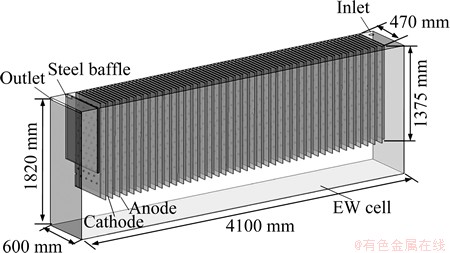
Fig. 1 Structure of zinc electrowinning cell
2.2 Governing equations
Ignoring the influence of the anode bubble on the flow, the flow field in zinc electrowinning can be described by [13]
 (1)
(1)
where replacement of  with the value 1 gives the continuity equation, from which for =U and Y, the momentum and mass transfer equation are obtained, respectively. Also, for =k and e, Equation (1) results in the appropriate expressions for the turbulent kinetic energy (k) and its rate of dissipation (e), both utilized by the k-e turbulence model. G and S are the diffusion coefficient and source term, respectively, and denote specific expressions for different equation.
3 Analysis of results
Here, the velocity of electrolyte 1.77 m/s is set at inlet, which corresponds to the flow rate of 25 m3/h, and the inlet angle is 0��. The outlet is defined as pressure boundary, the wall is specified as no-slipping boundary and wall function is used. A steel baffle with the height of 940 mm is located near the outlet [14,15].
3.1 Flow field on free surface
The velocity distribution of electrolyte on the free surface is shown in Fig. 2. It is obvious that there are two circulation flow zones where part of electrolyte flows backward the inlet from the side of cell and the rest flows directly toward the outlet. The separation of two circulations with opposite directions occurs at the 20th pair of anode-cathode. The velocity of electrolyte near the side is larger than that in the middle, and the velocity of backward is larger than that of the normal flow. The suspended matters in the electrolyte are accumulated near the inlet owing to the reflux, which are disadvantageous to the smooth flow of electrolyte.
In fact, the phenomenon of the backflow is observed in the real operation which is shown in Fig. 3. This is accordant with the result of simulation.
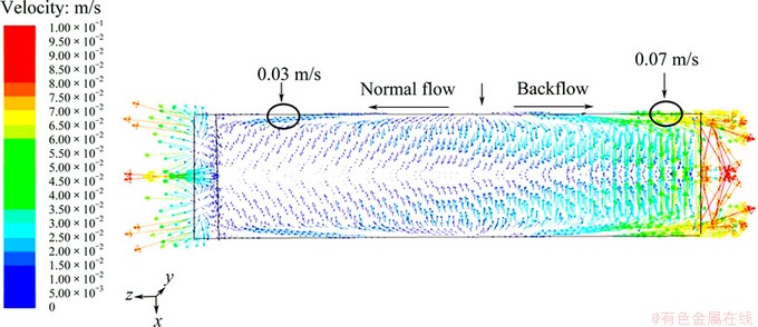
Fig. 2 Flow of surface in zinc electrolytic cell
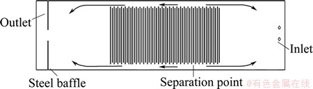
Fig. 3 Surface flow diagram of real zinc electrowinning
3.2 Flow field of electrolyte between anode and cathode
3.2.1 Steady of field
The velocity vector of electrode between anode and cathode is shown in Fig. 4. It can be seen that the electrolyte flows to upper cell from the bottom via the lateral part of zinc electrolytic cell and then downward at the center of the plates, which forms a large recirculation zone. Some electrolyte flows directly into the lower domain between anode and cathode from the side of cell, which consists of small eddy. Compared with the electrolyte below the electrode plates, the interelectrode electrolyte is of lower speed because of the larger resistance of the plates. As a whole, the quick movement of electrolyte between anode and cathode is helpful to holding the concentration of zinc ion and to reducing polarization phenomenon.
With the respect of different interelectrode electrolyte, the velocity is decreased gradually from the inlet to the outlet, for example, the farther the electrolyte from the entrance is, the smaller the average speed is, as shown in Fig. 4.
3.2.2 Unsteady flow field
To show the flow process of the electrolyte more clearly, the tracing method was applied to simulate the unsteady flow for the zinc electrowinning, and the coupling unsteady component transport equation is solved. It should be noticed that the tracer with the same physical characteristic as the background fluid was used. Therefore, the diffusion process of electrolyte can be estimated in terms of concentration field at different time. The concentration distributions at 300 and 600 s (Fig. 5) were selected and analyzed.
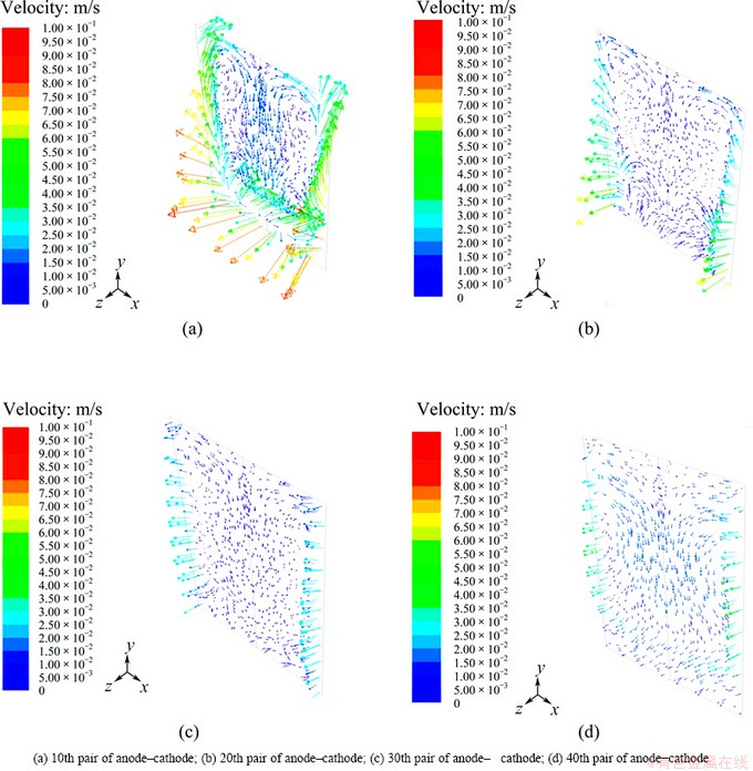
Fig. 4 Velocity distribution of interelectrode
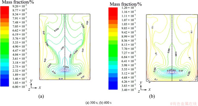
Fig. 5 Fraction of zinc sulfate at different time
Figure 5 shows that the concentration at the upper region between anode and cathode is higher than that at the bottom, which is accordant with steady velocity field. It is the reason that zinc deposited on the upper cathodes is thicker than that on the lower part in the real operation.
4 Interelectrode effective flow rate
Flow field of zinc electrolyte is changed with the variation of the cell structures and operating conditions. In general, the electrowinning efficiency will be enhanced with the increase of the electrolyte flow rate between anode and cathode. Then, the concept of the interelectrode effective rate (IEFR) was put forward to quantitatively describe the characteristics of the interelectrode flow field under different conditions.
IEFR (q) refers to the ratio of total flow rate Q of the electrolyte between anode and cathode to the total area A. Based on the mass conservation law and the control cell in Fig. 6, the inflow rate of interelecrtode equals the outflow in the case of steady-state flow, so IEFR is given as follows:
 (2)
(2)
where  and Aixz are the velocity and area of the i-th grid in xz plane, respectively;
  and Aiyz are the velocity and area of the i-th grid in yz plane, respectively.
Obviously, large IEFR is helpful to speeding up the refresh rate of electrolyte. Accordingly, polarization phenomenon will be depressed and the electrowinning efficiency be improved. Therefore, IEFR can be used as an evaluation index to optimize the flow field. For the technology of parallel flow proposed by ZHOU [10], IEFR is greatly increased by the jet-flow fixed between anode and cathode.
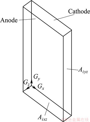
Fig. 6 Calculation diagram of interelectrode effective flow rate
5 Optimization of flow field
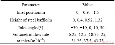
Without changing the basic structure of zinc electrolytic cell, the structure parameters and operating conditions, such as the angle, position and volumetric flow rate at inlet and the height of steel baffle could be optimized. The values calculated are listed in Table 1.
Table 1 Values of different parameters
During optimization, the designed condition in Section 2 was taken as a reference case, in which IEFR was 7.780 m/h.
5.1 Inlet angle
For the sake of simplicity of description and calculation, inlet angle is defined as the angle between the inflow direction of the electrolyte and the vertical direction, and the angle is positive if the inlet flows point to the outlet. The flow fields with the inlet angle from -30�� to 30�� were simulated. The major results are listed in Table 2.
Table 2 IEFR in case of different inlet angles
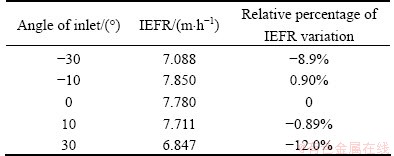
Table 2 shows that when the inlet angle varies from -30�� to 30��, IEFR reaches the maximum 7.85 m/h at inlet angle -10��. Therefore, the angle of inlet should be adjusted from -10�� to 10��, which will keep the large IEFR.
5.2 Inlet position
The inlet position of the reference case is located on the free surface of electrolyte and the point located below the free surface is negative. The flow fields with inlet positions at -0.9 and -1.5 m were calculated, respectively, and the results are listed in Table 3.
Table 3 IEFR at different inlet positions
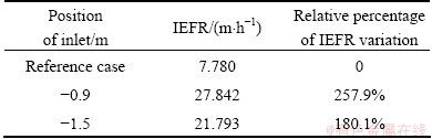
It is very clear that inlet position has vital influence on IEFR. Inlet position below free surface is helpful to improving IEFR. Compared with the inlet position at -1.5 m, there is a higher IEFR of 27.842 m/h in the case of the inlet position at -0.9 m. IEFR presents more than 257.9% of variations at inlet position of -0.9 m, contrasting with reference condition. Similarly, the inlet position at -1.5 m presents more than 180% of variations. However, in the real operation electrolyte, crystallization at inlet can be formed when inlet is located in the electrolyte, which will block the duct of electrolyte and reduce the flow rate. So, putting inlet under the free surface is an effective measure to greatly enhance IEFR if the electrolyte crystallization can be controlled.
5.3 Volumetric flow rate at inlet
The volumetric flow rate of electrolyte at inlet directly impacts IEFR by increasing circulating flux, and the variation tendency of IEFR with volumetric flow rate is shown in Fig. 7. It is obvious that IEFR is in proportion to the volumetric flow rate at inlet. Hence, greater flow rate at inlet, which raises circulation flux of electrolyte, is generally used to strengthen the flow of electrolyte between anode and cathode in real operation.
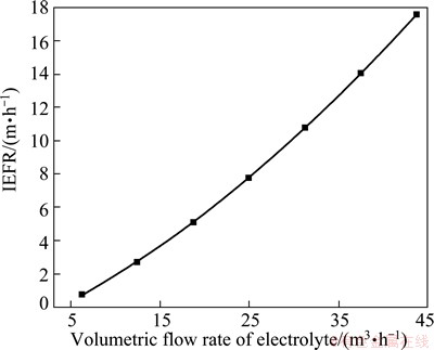
Fig. 7 IEFR in different flow rate
5.4 Steel baffle
The steel baffle is located in front of the outlet to prevent the electrolyte from directly flowing from the lateral part to the outlet. The flow fields with four sizes of height were modeled, respectively, and the main results are listed in Table 4.
Table 4 IEFR in different height of steel baffles
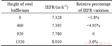
It can be seen that IEFR is enlarged with the increase of height of steel baffle, but the height of steel baffle has small influence on IEFR. Really, steel baffle is not applied in some industries.
6 Conclusions
1) On the free surface of zinc electrolyte cell, there are two circulation flow zones where part of electrolyte flows backward the inlet from the side of cell and the rest flows directly toward the outlet. The separation of two circulations with opposite directions occurs at the 20th pair of anode-cathode, and this phenomenon is observed in the real operation.
2) At the interelectrode zones, the electrolyte flows to the upper cell from the bottom via the lateral part of the cell and then downward at the center of the plates, resulting in the fact that zinc deposited on the upper cathodes is thicker than that on the lower part in the real operation. With the respect of different interelectrode electrolyte, the velocity is decreased gradually from the inlet to the outlet.
3) IEFR is defined as the ratio of total flow rate of the electrolyte between the anode and cathode to the total area. The influence of structure parameters and operation conditions on IEFR, such as the inlet angle, the volumetric flow rate, the inlet position and the height of steel baffle, were simulated. Summarily, the optimal parameters for the studied cell are as follows: inlet angle 0��; inlet position -0.9 m; the flow rate 25 m3/h; the height of steel baffle 1320 mm.
References
[1] TRIPATHY B C, DAS S C, MISRA V N. Effect of antimony on the electrocrystallisation of zinc from sulphate solutions containing SLS [J]. Hydrometallurgy, 2003, 69(1-3): 81-88.
[2] ZHU Yong-xiang. Production practices on peducing the unit loss of zinc electrolytic DC current [J]. Hunan Nonferrous Metals, 2007, 23(3): 22-25. (in Chinese)
[3] BRETT C M A, BRETT A M O. Electrochemistry, principles, methods and applications [M]. Oxford: Oxford University Press, 1993.
[4] SCHWARZ M P. Improving zinc processing using computational fluid dynamics modeling successes and opptunities [J]. Minerals Engineering, 2012, 30: 12-18.
[5] XU Cai-dong, LIN rong, WANG Da-cheng. Physical and chemistry of zinc metallurgy [M]. Shanghai: Shanghai Scientific and Technical Press, 1977. (in Chinese)
[6] ASHRAF B A, PUSHPAVANAM S. Analysis of liquid circulation and mixing in a partitioned electrolytic tank [J]. Multiphase Flow, 2011, 37(9): 1191-1200.
[7] JIANG Ji-mu. Status and sustainable development of leadand zinc smelting industry in China [J]. The Chinese Journal of Nonferrous Metals, 2004, 4(1): 52-62. (in Chinese)
[8] SKOOG D A. Principles of instrumental analysis [M]. New York: Sanders College Publishing, 1985.
[9] LI Shi-xiong, XIE Da-yuan, LIN Sheng-dao. Industrial control of copper electrolysis additive [J]. The Chinese Journal of Nonferrous Metals, 2004, 14(1): 132-137. (in Chinese)
[10] ZHOU Song-lin. Research and application of low carbon copper smelting process [J]. China Nonferrous Metallurgy, 2010, (4): 1-4, 53. (in Chinese)
[11] MARTIN J L, SCHWARZ M P. Experimental validation of a computational fluid dynamics model of copper eletrowinning [J]. Metallurgical and Materials Transactions B, 2010, 41(6): 1247-1260.
[12] WANG Jian-wei, LUO Yong-guang, SHI Zhe. Hydraulics and numerical simulation of flow at electrolyte in zinc electrolysis Cell [J]. Nonferrous Metals, 2011, 8: 4-8. (in Chinese)
[13] SUHAS V. PATANLAR. Numerical heat transfer and fluid flow [M]. New York: Hemisphere Pulishing Corporation, 1980.
[14] HERRERO D, ARIAS P L, GUEMEZ B, CAMBRA J F. Hydrometallurgical process development for the production of a zinc sulphate liquor suitable for electrowinning [J]. Minerals Engineering, 2010, 23(6): 511-517.
[15] SCHWARZ M P, BOND A M. Improving zinc processing using computational fluid dynamics modelling�CSuccesses and opportunities [J]. Minerals Engineering, 2012, 30: 12-18.
����������ֵģ���п���۲����������ṹ�����Ż�
����1���� ��2���� Ƽ1��κ����2��������1
1. ���ϴ�ѧ ��Դ��ѧ�빤��ѧԺ����ɳ 410083��
2. ����ұ�����Źɷ�����˾������ 412004
ժ Ҫ����п����Ϊ������Fluent�����Ե����ڵ��Һ�ĵ����������̽�����ֵģ�⡣������ģ��������������Һ����20�鼫�崦���ڷ����෴�Ļ��������ֳ��۲������һ�£��ڼ�������������Һ�Ӳಿ�������������䡣����������������������Ч�����ĸ����ͬʱ�����������������ĵ��Һ��������ͨ���֮�ȡ����ü�����Ч������Ϊ����ָ������п���۲����������ṹ��������ڽǶȡ�������������λ�õȽ����Ż���������������λ��Һ����0.9 m������ڽǶ���-10�㵽10��֮��������ļ�����Ч������������Ч���������������������ȣ����ֵ����Ӱ����Ժ��ԡ�
�ؼ��ʣ�п���ۣ��������Ż�����ֵģ��
(Edited by Chao WANG)
Foundation item: Project (2011AA061003) supported by the National High-Tech Research and Development Program of China
Corresponding author: Ping ZHOU; Tel: +86-13975804856; E-mail: zhoup@csu.edu.cn
DOI: 10.1016/S1003-6326(14)63231-3
Abstract: The physical and mathematical model of an operating electrowinning cell was established, and the flow of electrolyte was numerically simulated by the commercial software Fluent. The results indicate that there are two circulations at the surface flow where part of electrolyte backflows to the inlet from the side of cell, and the rest flows directly to the outlet, and the separation of two circulations with opposite direction occurs at the 20th pair of anode-cathode. This phenomenon was observed in the real operation. The electrolyte flows into the space between anode and cathode from the side portion of the cell. Meanwhile, the interelectrode effective flow rate (IEFR) is put forward to describe quantitively the flow field characteristics and is defined as the ratio of electrolyte flow between the anode and cathode to the total flow area. The influences of structure parameters and operating conditions on IEFR, such as the inlet angle, the volumetric flow rate, the inlet position and the height of steel baffles were simulated. The inlet position has a significant influence on the IEFR and its optimal value is 0.9 m below free surface. The inlet angle should be in the range from -10�� to 10��. IEFR is in linear proportion with the volumetric flow rate, and the height of the steel baffle has little influence on the flow field.
