
Trans. Nonferrous Met. Soc. China 30(2020) 3254-3262
Microstructure and tensile properties of rapid-cooling friction-stir-welded AZ31B Mg alloy along thickness direction
Nan XU, Wei-da ZHANG, Si-qi CAI, Yue ZHUO, Qi-ning SONG, Ye-feng BAO
College of Mechanical and Electrical Engineering, Hohai University, Changzhou 213022, China
Received 21 April 2020; accepted 13 October 2020
Abstract:
Rapid-cooling friction-stir-welding (FSW) was used to join AZ31B magnesium alloy plates of 6 mm in thickness. The microstructure and mechanical properties in thickness direction were carefully investigated with electron backscattered diffractometer, and transmission electron microscope. The obtained results showed that ultrafine grains with high dislocation density were obtained in the top region of the weld due to liquid CO2 cooling. A large number of  twins and second-phase particles were also induced in these refined grains. The basal texture intensity was significantly reduced due to the appearance of twins. The top region showed the higher strength and elongation compared with the bottom region, and the welding efficiency reached 93%. This work provided a simple and efficient strategy for manufacturing a gradient structure in the FSW Mg alloy joint.
Key words:
friction stir welding; magnesium alloy; recrystallization; texture; microstructure; mechanical properties;
1 Introduction
Mg alloy is a key material for lightweight structures. Recently, the use of large and complex Mg alloy components in aerospace, rail transit, and automobile manufacturing has significantly increased [1]. In the manufacture of large and complex Mg alloy components, the use of welding technology is inevitable. Friction stir welding (FSW) is a new solid-state joining technology which usually operates below the melting point of the materials; therefore, the defects of traditional fusion welding can be completely avoided [2]. For wrought Mg alloys, although the grain in the weld is remarkably refined, the yield strength and the elongation of the welded joint are unsatisfactory [3]. The poor mechanical properties of FSW joints so far limited the further application of wrought Mg alloys. Therefore, refining the microstructure and improving the mechanical properties of FSW wrought Mg alloy joints are the keys and urgently need to be solved.
MISHRA and MA [4] reported that dynamic recrystallization (DRX) occurred during the FSW process. The dislocation density significantly decreased in the joint, leading to a decrease in mechanical properties of the joint. AFRIN et al [5] tried to improve the mechanical properties of the joint by grain refinement; however, the results were not satisfactory. FSW can significantly change the grain orientation of AZ31B Mg alloy, leading to the (0001) basal plane of most grains in the joint parallel to the surface of the probe. Subsequently, NIA et al [6] reported that due to different grain orientations between base metal (BM) and weld, fracture easily occurre at the BM/weld interface. The strong basal texture weakened the effect of grain refinement on the mechanical properties of the joints, which is the main reason for the poor mechanical properties of FSW-wrought Mg alloy joints. In recent years, rapid cooling FSW (RC-FSW) technology has been developed to reduce the processing temperature and increase the cooling rate of FSW joints [7]. This process is designed to optimize the microstructure and mechanical properties of FSW joints by improving the welding thermal cycle. By using various cooling media, the peak temperature decreased, and the cooling rate increased. Previous studies were mainly focused on the welding of a thin plate of ~2 mm. The temperature, strain rate, and cooling rate of the weld were similar in the whole welded joint; therefore, the obtained microstructure was relatively uniform. However, in the manufacture of Mg alloy structural components, thick plates (5-20 mm) are typically used. When the RC-FSW was conducted on thick Mg alloy plates, the temperature, strain rate, and cooling rate in the weld thickness direction may be different. This would result in the occurrence of inhomogeneous microstructures and mechanical properties in the joints. Therefore, in this work, the RC-FSW was conducted on AZ31B Mg alloy plates with 6 mm in thickness. The microstructure and mechanical properties were carefully investigated along the plate-thickness direction.
2 Experimental
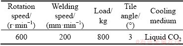
In this work, a load-controlled FSW equipment (FSW-LM-BM16, FSW Center, Beijing, China) was used to join commercial AZ31B Mg alloy plates with a dimension of 300 mm �� 300 mm �� 6 mm. The tool shoulder diameter was 20 mm, the tool probe height was 5.8 mm, and its diameter was 8 mm. A schematic diagram of the RC-FSW process and the welding parameters are shown in Fig. 1(a) and Table 1, respectively. During the welding process, liquid CO2 (-78 ��C) was used for rapid cooling. For details on liquid CO2 cooling, readers can refer to our previous publication [7]. Two K-type thermocouples were placed at the surface and back of the plate to record the temperature histories of the top region and the bottom region of the welded joint.
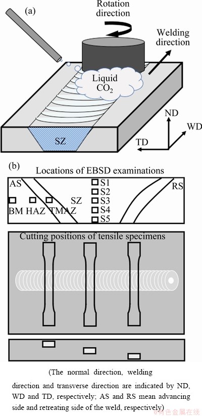
Fig. 1 Schematic diagram of RC-FSW process (a) and locations of EBSD examinations and cutting positions of tensile specimens (b)
Table 1 RC-FSW conditions used in this study
After welding, a cross-sectional sample was cut perpendicular to the welding direction. The sample was corroded with a mixture solution of 10 g picric acid, 175 mL ethanol, 25 mL acetic acid, and 25 mL distilled water, and then an optical microstructure (OM) examination was performed. According to different microstructural features of the weld (Fig. 1(b)), FSW joints are commonly divided into four areas: the stir zone (SZ), the thermo-mechanically affected zone (TMAZ), the heat-affected zone (HAZ), and base material (BM) [8]. Electron back-scattered diffraction (EBSD) was used to characterize the above regions. EBSD samples were electropolished by using a mixture solution of methanol, glycerin and nitric acid (volume ratio of 6:3:1) to remove mechanical stress. The EBSD system was installed in a field emission scanning electron microscope (FE-SEM), and the scanning step was set to be 0.2 ��m. According to the GB T228.1��2010 standard, the tensile specimens were cut perpendicular to the welding direction at different positions (Fig. 1(b)). The gauge size of the tensile specimen was 40 mm (length) �� 10 mm (width) �� 2 mm (thickness). An Instron tensile test machine was used to conduct tensile tests at a speed of 1 mm/min at room temperature. Finally, transmission electron microscopy (TEM) was used on the SZ during the tensile test to examine the development of the substructure. TEM samples were initially mechanically thinned to 50-100 ��m. Then, the thin sample was double-jetted at 20 V and -30 ��C. The acceleration voltage of TEM was 200 kV.
3 Results and discussion
3.1 Temperature history
The temperature history of surface and bottom of the weld is shown in Fig. 2. The surface region and the bottom region showed different peak temperatures of 195 and 307 ��C, respectively. Furthermore, they also underwent different cooling rate depending on the distance from the liquid CO2 nozzle. For the surface region, the temperature first slowly decreased to -36 ��C due to the liquid CO2 cooling, and then sharply increased when the rotating tool approached. As the rotating tool went through the measurement point, the weld surface was cooled from the peak temperature to the room temperature in about 3.2 s. In contrast, because the heat diffusion in the bottom region became slower than that of the surface region, the temperature initially decreased to 9 ��C, then suddenly increased to 307 ��C, and finally decreased to room temperature in about 18.7 s. Clearly, both the peak temperature and the high temperature exposure time were remarkably reduced in the weld surface region due to the strong cooling capacity of liquid CO2.
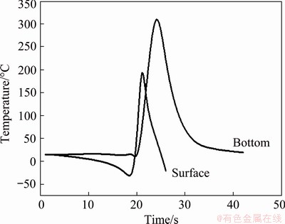
Fig. 2 Temperature history of surface and bottom of weld
3.2 Macro- and micro-structure characterization
3.2.1 Surface appearance and cross-section over- view
Figure 3 shows the surface appearance and cross-section overview of the RC-FSW AZ31B Mg joint. Defects such as tunnel, pore and kissing bond were not detected, indicating that a sound joint was successfully achieved. A cup-shaped SZ can be clearly seen in the center of the weld. However, the SZ area is relatively small compared to that of the basin-shaped SZ produced by conventional FSW. The reason for this is that the stirred volume in the top region decreased with the reduction in material flow ability caused by the liquid CO2 cooling.
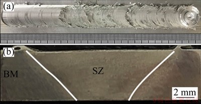
Fig. 3 Surface appearance (a) and cross-sectional over- view (b) of weld
3.2.2 OM examination
Figure 4 shows the OM images of BM, HAZ, TMAZ and SZ center of the welded joint. The locations of OM examination were illustrated in Fig. 1(b). The BM and the HAZ exhibited a similar inhomogeneous grain structure, indicating that the HAZ was eliminated in the present study. Grains in the TMAZ distributed aligned with the material flow direction, and they were also partially refined due to increased plastic strain and temperature. Also, several twins were found in some grains. The SZ center exhibited a homogeneous recrystallized grain structure, and the grain size was reduced compared to the other regions. To study the details of microstructural development, the welded joint was further examined by EBSD and TEM examinations.
3.2.3 EBSD and TEM characterization
The EBSD results of BM and HAZ are shown in Fig. 5. The average grain size, the ratio of high angle grain boundary (HAGB), and rolling texture were very similar, indicating that no obvious HAZ was formed in this study. During the welding, the use of cooling medium diffused the heat rapidly, and completely eliminated the HAZ. This phenomenon has been confirmed in our previous study [7].
Figure 6 shows the EBSD results of TMAZ. The TMAZ consisted of a mixture of large and small grains with an average grain size of 6.1 ��m. Because the TMAZ was subjected to partial thermoplastic deformation during the welding process, incomplete recrystallization occurred. Since most grains in TMAZ had basal slip, the {0002} plane almost paralleled to the grain deformation direction. At the same time, several twins were found at TMAZ. The enlarged EBSD map showed the following four grain refinement mechanisms during the welding process:
(1) Continuous DRX. Massive dislocations were produced in the original grains caused by the intense shear deformation. The dislocation rearrangement promoted the generation of dislocation cell. Then, the dislocation cell changed into low angle grain boundary (LAGB) and finally into HAGB [9]. The typical microstructural feature of CDRX is characterized by HAGB fragments near the original grain boundary (indicated by Arrow 1 in Fig. 6).
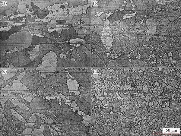
Fig. 4 OM images of BM (a), HAZ (b), TMAZ (c) and SZ center (d) of RC-FSW AZ31B Mg joint
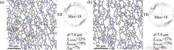
Fig. 5 EBSD results of BM (a) and HAZ (b) (HAGB (�ȡ�15��, black lines), LAGB (2��ܦ�<15��, blue lines), and TB (��=86��, red lines) denote high-angle boundary, low-angle boundary, and  twin boundary, respectively)
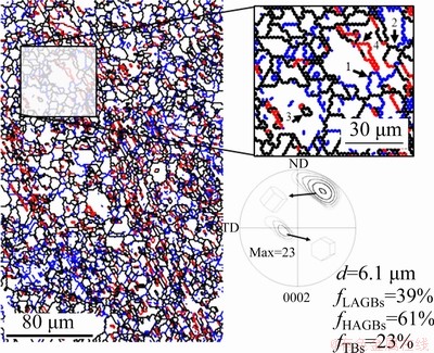
Fig. 6 EBSD results of TMAZ
(2) Discontinuous DRX. In stirring, the grain boundaries between two grains became serrated due to the local strain concentration at the interaction of the grains. With increasing strain, a subgrain boundary formed near the serrated grain boundary, which then grew to form a necklace shape around the original grain (indicated by Arrow 2 in Fig. 6). This necklace shape was a typical sign of DDRX [10].
(3) Grain subdivision. As indicated by Arrow 3 in Fig. 6, a new grain was produced in the original grain interior. Due to the uniformity of the plastic deformation, the micro-shear bands from different directions occurred within the original grain [11]. With continuing deformation, the misorientation of the micro-shear bands gradually increased. Especially at the intersections of the micro-shear bands, the misorientation increased rapidly, and they firstly transformed into HAGBs, thus resulting in the formation of new grains.
(4) Twining-induced DRX. Several special new grains can be found within the original grain, as indicated by Arrows 4 in Fig. 6. The grain boundaries of these new grains were twins. During the welding process, the intense shear deformation promoted the production of twins, and the long and straight twin boundary immediately changed into a serrated shape as a result of the continuously increased strain. Then, serrated twin boundaries (TBs) fastened together, and finally formed equiaxed grains with twin orientated at the boundaries [12].
The SZ was located at the weld center, and experienced severe thermoplastic deformation during welding. Temperature and strain rate are two important parameters in the plastic deformation process, and their influence on the microstructure of the material is often consistent. The combination of strain rate and temperature on the plastic deformation is usually described by the Zener- Holloman (Z) parameter [13]:
 (1)
(1)
where Q represents activation energy, R represents gas constant, T represents thermodynamic temperature, and  represents strain rate. In general, the higher temperature leads to the easier dynamic recrystallization; however, the ability of grain boundary migration increases, thus resulting in grain coarsening. The higher strain rate leads to the easier dislocation generation, and thus, the nucleation rate increases. This makes recovery difficult to occur and grain growth is inhibited. When plastic deformation occurs, the Z parameter increases by decreasing the temperature or increasing the strain rate, so that ultrafine grains or even nanocrystals can be obtained. Especially for HCP metals with few slip systems, with increasing Z parameter, the plastic deformation is usually coordinated by twinning. Furthermore, the cooling rate after deformation exerts an important effect on the microstructure as well. The higher the cooling rate is, the smaller the grain growth trend of deformed grains will be; therefore, it is easier to obtain fine grains.
To study the influence of temperature, strain rate, and cooling rate on the microstructure of the welded joint, five regions were selected in the SZ thickness direction for EBSD characterization, and the obtained results are shown in Fig. 7. The average grain size of the S1 and S2 regions was smaller than that of the BM, indicating that there was significant grain refinement on the top region of the welded joint.
The microstructure difference in thickness direction was due to the different processing temperatures, strain rates, and cooling rates in each region. The processing temperature of S1 region was much lower than that of the S5 region. A previous research reported that from top region to bottom region in the FSW process, the strain rate gradually decreased due to the reduction of material fluidity [14]. Based on Eq. (1), the lower temperature and the higher strain rate led to a higher Z value of the S1 region than that of the S5 region. It is known that the size of recrystallized grain decreases with Z value increasing. Moreover, the relatively high cooling rate in the S1 region inhibited the grain growth because it was closest to the cooling medium.
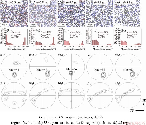
Fig. 7 Grain boundary map (a1-a5), histogram of misorientation angle distributions (b1-b5), {0002} (c1-c5), and  (d1-d5) pole figures of weld center along plate thickness direction
In addition, the (0002) and  pole figures showed that different locations also had different textural features. The texture in S1 and S2 regions showed two components including <0002>//WD and <0002>//ND, and the S3-S5 regions mainly consisted of <0002>//WD component. In the S5 region, the dominant plastic deformation was basal due to the fact that the Z value was relatively small. Thus, the {0002} plane of most grains tended to align with the surface of the probe, which enhanced the <0002>//WD component [15]. In the S1 region, the <0002>//ND component increased, while the <0002>//WD component decreased. The Z value of the S1 region was high, and thus twinning behavior was activated. The twinning behavior can be activated by the compressive deformation perpendicular to the c-axis and/or by tensile deformation along the c-axis [16]. For FSW, the compressive and tensile deformation can be simultaneously provided by the axial force and the shear force. In order to reduce the strain concentration in the direction of c-axis, twins on the twinning behavior were more suitable than that of the bottom region; therefore, a large number of twins were produced in S1 and S2 regions. The occurrence of twins can reorientate the basal plane to normal direction by 86.3��, thus weakening the basal texture intensity in the upper region.
Figure 8 shows backscattered electron images of the top (S1) region and the bottom (S5) region. Much of precipitated particles were found in the S1 region, but not in the S5 region, indicating that the precipitated particles nonuniformly distributed in the SZ along the thickness direction. For AZ31B Mg alloys, precipitated phase was usually identified as ��-Mg17Al12, and it was confirmed by TEM examination, as shown in Fig. 9. Interestingly, ��-Mg17Al12 particles were just detected in the top region of the SZ. The eutectic ��-Mg17Al12 phase can dissolve into the ��-Mg matrix at about 220 ��C due to its poor thermal stability [17]. For S1 region, the welding peak temperature was much lower than the Mg-Al phase transformation temperature as shown in Fig. 2; thus, the eutectic ��-Mg17Al12 phase was maintained in the weld top region.
3.3 Mechanical properties
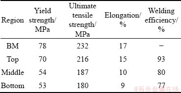
Table 2 summarizes the tensile tests results of the BM and the welded joints of different thicknesses. Although the average grain sizes of the bottom and central regions were similar to those of the BM, the yield strength, tensile strength and elongation were lower than those of the BM due to the strong basal texture. The grain size of the top region was finer than that of the BM, and the basal texture intensity was weaker than that of the middle and bottom region. Therefore, the yield strength and tensile strength of the top region were close to those of the BM, and the welding efficiency reached 93%. More importantly, the elongation did not decrease significantly. Obviously, a good strength-ductility synergy was obtained at the top area.
Based on the TEM characterization, which was conducted on the tensile tested sample of the top region, it was found that the strength and ductility improvement in the top region could be attributed to the following three factors:
(1) Residual stresses. The liquid CO2 cooling introduced a ��thermal tensioning�� effect on the weld surface counteracting the forces which lead to residual stresses and distortion [18]. STARON et al [19] investigated the effect of liquid CO2 cooling on the residual stress state of FSW Al sheets using the neutron strain scanning technique. It was found that liquid CO2 cooling can significantly reduce tensile residual stresses in the weld region and even produce beneficial compressive stresses. As shown in Fig. 2, an obvious temperature gradient distribution can be detected in the weld thickness direction. The liquid CO2 cooling decreases the peak temperature, narrows the distribution range of high temperature and reduces residual tensile stress in the surface area where the reducing effect was greater than that in the bottom. The residual tensile stress in the top region was smaller than that in the bottom region. The reduced residual tensile stress was beneficial to the enhancement of tensile strength in the top region.
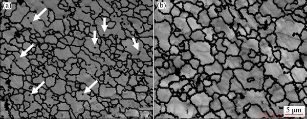
Fig. 8 Backscattered electron images of S1 region (a) and S5 region (b)
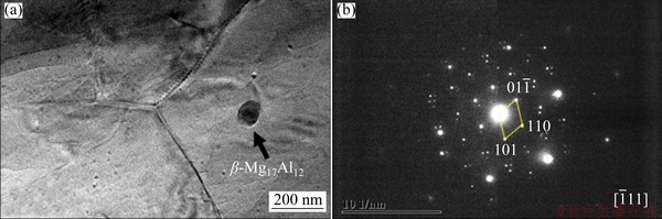
Fig. 9 Bight field TEM image (a) and selected electron diffraction pattern (b) of precipitated particle in top region (S1) of weld
Table 2 Tensile test results of weld joint in top, middle, and bottom regions as well as BM
(2) The second phase particles. There were many precipitated phases in the S1 region but was almost none in the S5 region. According to the TEM examination, the precipitated particles were ��-Mg17Al12 phases. The deformation temperature of the top region was lower than the Mg-Al phase transformation temperature due to the liquid CO2 cooling. The ��-Mg17Al12 cannot dissolve into the ��-Mg matrix. The dislocation line could be bent around the second phase particles when plastic deformation occurred. Finally, as the dislocation passed through, a dislocation loop was left around the second phase particle. The bending of the dislocation line increased the lattice distortion energy of the dislocation-affected area, which increased the resistance of the dislocation line movement and increased the slip resistance [20].
(3) twins. During the tensile test, the active base slip can produce a full dislocation. When this dislocation moves to the TB, it can be decomposed into two partial dislocations. One partial dislocation goes into the twin interior, and the other partial dislocation (the so-called Shockley dislocation) remains at the TB. The Shockley dislocation can slip along the TB, resulting in the migration of TB [21]. This process can release the stress concentration and let the TB effectively absorb strain [22]. Therefore, the elongation of the welded joint was improved during the tensile test.
4 Conclusions
(1) HAZ which usually deteriorates the mechanical properties of the welded joint was successfully eliminated due to the improved thermal cycle.
(2) The peak temperature and the high- temperature exposure time in the weld surface region were remarkably reduced compared with those of the bottom region.
(3) The top SZ of the weld showed the finest grain structure with abundant twins and ��-Mg17Al12 particles, whereas the bottom SZ exhibited a simple solid solution structure. An obvious gradient structure was produced in the weld thickness direction.
(4) The grain refinement mechanism during the welding was attributed to the combination of continuous DRX, discontinuous DRX, grain subdivision and twinning-induced DRX.
(5) The top region of the weld joint showed the highest strength and elongation, and the welding efficiency was enhanced to be 93%. A good combination of strength and ductility was achieved in the weld top region.
References
[1] WU Shu-xu, WANG Shou-ren, WANG Gao-qi, YU Xiu-chun, LIU Wen-tao, CHANG Zheng-qi, WEN Dao-sheng. Microstructure, mechanical and corrosion properties of magnesium alloy bone plate treated by high-energy shot peening [J]. Transactions of Nonferrous Metals Society of China, 2019, 29: 1641-1652.
[2] BARADARANI F, MOSTAFAPOUR A, SHALVANDI M. Effect of ultrasonic assisted friction stir welding on microstructure and mechanical properties of AZ91-C magnesium alloy [J]. Transactions of Nonferrous Metals Society of China, 2019, 29: 2514-2522.
[3] COMMIN L, DUMONT M, MASSE J E, BARRALLIER L. Friction stir welding of AZ31 magnesium alloy rolled sheets: Influence of processing parameters [J]. Acta Materialia, 2008, 57: 326-334.
[4] MISHRA R S, MA Z Y. Friction stir welding and processing [J]. Materials Science and Engineering R, 2005, 50: 1-78.
[5] AFRIN N, CHEN D L, CAO X, JAHAZI M. Microstructure and tensile properties of friction stir welded AZ31B magnesium alloy [J]. Materials Science and Engineering A, 2007, 472: 179-186.
[6] NIA A A, OMIDVAR H, NOURBAKHSH S H. Effects of an overlapping multi-pass friction stir process and rapid cooling on the mechanical properties and microstructure of AZ31 magnesium alloy [J]. Materials and Design, 2014, 58: 298-304.
[7] XU N, UEJI R, MORISADA Y, FUJII H. Modification of mechanical properties of friction stir welded Cu joint by additional liquid CO2 cooling [J]. Materials and Design, 2014, 56: 20-25.
[8] XU Wei-feng, MA Jun, WANG Miao, LU Hong-jian, LUO Yu-xuan. Effect of cooling conditions on corrosion resistance of friction stir welded 2219-T62 aluminum alloy thick plate joint [J]. Transactions of Nonferrous Metals Society of China, 2020, 30: 1491-1499.
[9] DING Tian, YAN Hong-ge, CHEN Ji-hua, XIA Wei-jun, SU Bin, YU Zong-lin. Dynamic recrystallization and mechanical properties of high-strain-rate hot rolled Mg-5Zn alloys with addition of Ca and Sr [J]. Transactions of Nonferrous Metals Society of China, 2019, 29: 1631-1640.
[10] ZHONG Xi-ting, HUANG Lin-ke, WANG Lei, LIU Feng, DONG Xiao-ming, ZHANG Zhong-hua. A discontinuous dynamic recrystallization model incorporating characteristics of initial microstructure [J]. Transactions of Nonferrous Metals Society of China, 2018, 28: 2294-2306.
[11] CHEN Xiang, HUANG Guang-sheng, LIU Shuai-shuai, HAN Ting-zhuang, JIANG Bin, TANG Ai-tao, ZHU Yun-tian, PAN Fu-sheng. Grain refinement and mechanical properties of pure aluminum processed by accumulative extrusion bonding [J]. Transactions of Nonferrous Metals Society of China, 2019, 29: 437-447.
[12] XU Nan, SONG Qi-ning, BAO Ye-feng.  twinning assisted microstructure and mechanical properties modification of high-force friction stir processed AZ31B Mg alloy [J]. Materials Science and Engineering A, 2019, 745: 400-403.
[13] CHANG C I, LEE C J, HUANG J C. Relationship between grain size and Zener-Holloman parameter during friction stir processing in AZ31 Mg alloys [J]. Scripta Materialia, 2004, 51: 509-514.
[14] NANDAN R, ROY G G, LIENERT T J, DEBROY T. Three-dimensional heat and material flow during friction stir welding of mild steel [J]. Acta Materialia, 2007, 55: 883-895
[15] MIRONOV S, ONUMA T, SATO Y S, YONEYAMA S, KOKAWA H. Tensile behavior of friction-stir welded AZ31 magnesium alloy [J]. Materials Science and Engineering A, 2017, 679: 272-281.
[16] WU Hai-chen, YU You-xing, BI Xiao-fang. Atomic scale structural characterization of twin boundaries in zinc [J]. Transactions of Nonferrous Metals Society of China, 2018, 28: 1538-1542.
[17] MASSALSKI T B. Binary alloy phase diagram [M]. Ohio: ASM International, 1986.
[18] GUAN Qiao, GUO De-luen, LI Cong-qing. Low stress non-distortion (LSND) welding��A new technique for thin materials [J]. Transactions of the China Welding Institution, 1994, 11: 231-237. (in Chinese)
[19] STARON P, KOCAK M, WILLIAMS S. Residual stresses in friction stir welded Al sheets [J]. Applied Physics A, 2002, 74: 1161-1162.
[20] WANG F, BHATTACHARYYA J J, AGNEW S R. Effect of precipitate shape and orientation on Orowan strengthening of non-basal slip modes in hexagonal crystals, application to magnesium alloys [J]. Materials Science and Engineering A, 2016, 666: 114-122.
[21] FENG H, FANG Q H, LIU B, LIU Y, LIU Y W, WEN P H. Nucleation and growth mechanisms of nanoscale deformation twins in hexagonal-close-packed metal magnesium [J]. Mechanics of Materials, 2017, 109: 26-33.
[22] LU K, LU L, SURESH S. Strengthening materials by engineering coherent internal boundaries at the nanoscale [J]. Science, 2009, 324: 349-352.
AZ31Bþ�Ͻ������ȴ����Ħ�������ȷ��������֯����ѧ����
�� 骣���ΰ���˼�棬 Խ�������������ʷ�
�Ӻ���ѧ ���繤��ѧԺ, ���� 213022
ժ Ҫ�����õ��ӱ�ɢ�������Ǻ�����������о�������ȴ��6 mm��AZ31Bþ�Ͻ����Ħ�������ȷ��������֯����ѧ���ܵ�Ӱ�졣���������Һ̬������̼��ȴ�ɴٽ����춥���γɾ��и�λ���ܶȡ����� �Ͼ��͵ڶ��������ϸ���ṹ���Ͼ�ʹ���춥������Ļ���֯���������͡���ͷ���������ǿ�ȺͶϺ��쳤�ʽϵײ������������ߣ�����Ч�ʿɴ�93%����Ϊ��þ�Ͻ����Ħ������ͷ���Ʊ��ݶȽṹ�ṩһ�ּ���Ч�ķ�����
�ؼ��ʣ�����Ħ������þ�Ͻ��ٽᾧ��֯��������֯����ѧ����
(Edited by Bing YANG)
Foundation item: Project (51805145) supported by the National Natural Science Foundation of China; Project (CJ20200076) supported by the Changzhou Science and Technology Program, China; Project (B200202229) supported by the Fundamental Research Funds for the Central Universities of China; Project (2020102941517) supported by Hohai University Undergraduate Innovation and Entrepreneurship Training Program, China
Corresponding author: Nan XU; Tel/Fax: +86-519-85192039; E-mail: xunan@hhu.edu.cn, xunan20032389@126.com
DOI: 10.1016/S1003-6326(20)65458-9
Abstract: Rapid-cooling friction-stir-welding (FSW) was used to join AZ31B magnesium alloy plates of 6 mm in thickness. The microstructure and mechanical properties in thickness direction were carefully investigated with electron backscattered diffractometer, and transmission electron microscope. The obtained results showed that ultrafine grains with high dislocation density were obtained in the top region of the weld due to liquid CO2 cooling. A large number of twins and second-phase particles were also induced in these refined grains. The basal texture intensity was significantly reduced due to the appearance of twins. The top region showed the higher strength and elongation compared with the bottom region, and the welding efficiency reached 93%. This work provided a simple and efficient strategy for manufacturing a gradient structure in the FSW Mg alloy joint.
