

J. Cent. South Univ. (2021) 28: 604-617
DOI: https://doi.org/10.1007/s11771-021-4625-x

Analysis of tunnel face stability with advanced pipes support
AN Yong-lin(������), ZHOU Jin(�ܽ�), OUYANG Peng-bo(ŷ������), LI Jia-hao(��Ѻ�)
School of Civil Engineering, Hunan University of Science and Technology, Xiangtan 411201, China
 Central South University Press and Springer-Verlag GmbH Germany, part of Springer Nature 2021
Abstract:
To keep the tunnel face stable is very important for tunnel construction. In this paper, the tunnel face stability under the advanced pipe was analyzed using the Winkler foundation model and rigid limit equilibrium. The tunnel face deformation characteristics were also analyzed using the numerical simulation. The influence of parameters on the deflection of the pipe roof and the stability of the tunnel face were discussed. The results show that the tunnel face stability can be improved through increasing the pipe diameter, decreasing the initial displacement at the beginning of the pipe seat, and adopting the short round length and small excavation height. With the increase of tunnel burial depth, the safety factor of tunnel face stability first decreases, then increases, and then remains unchanged. The deformation at the center of the tunnel face is larger than the deformation at the surround sides and at the corner. The horizontal displacement varies little with the increasing of the pipe length. The horizontal displacement at the center of the tunnel face increases with the increase of the pipe ring spacing and the pipe longitudinal spacing. There is an optimum external angle.
Key words:
tunnel face stability; advanced pipe; Winkler foundation model; numerical simulation��
Cite this article as:
AN Yong-lin, ZHOU Jin, OUYANG Peng-bo, LI Jia-hao. Analysis of tunnel face stability with the advanced pipes support [J]. Journal of Central South University, 2021, 28(2): 604-617.
DOI:https://dx.doi.org/https://doi.org/10.1007/s11771-021-4625-x1 Introduction
Rapid urbanization and the development of China��s economy have seen the construction of many underground facilities in urban areas of China, including subway tunnels, road tunnels and railway tunnels [1, 2]. The mountain tunneling method is presently used for soft grounds with shallow depths in urban areas. This method is less expensive to apply, in comparison to the shield tunneling method, and it can easily change the shape of a tunnel��s cross section. The method often employs auxiliary methods, such as the pipe roof support system, in order to avoid serious consequences to the surrounding environment [3].
During tunnel construction using mountain tunneling method [1], the stability of the tunnel face is of importance for safe construction. At present, the research on the stability of the tunnel face mainly focuses on the following aspects: the analysis of the tunnel face stability in weak surrounding rock [4], the influence of core soil on the tunnel face stability [5], and the deformation control of the soil in front of the tunnel face of ADECO-RS [6]. The calculation methods of tunnel face stability mainly include limit analysis method [7], limit equilibrium method [8], test method [9], and numerical simulation by software [10].
Because NATM is different from shield method and there is no soil chamber, it is unreasonable to use support force to express it.
Some scholars put forward the concept of virtual support force [11, 12], and analyzed the stability of tunnel face with strength reduction method and limit analysis method. For the advanced pipe, some scholars have made analysis on the principle of the pipe roof, and the advance support mechanism [3, 13-17], etc. However, there are few studies on the stability of the tunnel face under the action of the pipe roof.
In this paper, the tunnel face stability under the advanced pipe was analyzed using the Winkler foundation model and rigid limit equilibrium. The tunnel face deformation characteristics were also analyzed using the numerical simulation. The influence of parameters on the deflection of the pipe roof and the stability of the tunnel face are discussed.
2 Stability analysis model of tunnel face supported by pipe roof
2.1 Mechanical model
The mechanical model of the advanced pipe is shown in Figure 1(a), and mechanical model of the tunnel face stability is shown in Figure 1(b).
The foundation is supposed to be a Winkler model, and the foundation counter stress is derived from the following equation:
p(x)=k��(x) (1)

Figure 1 Mechanical model of advanced pipe and face:
where k is the coefficient of subgrade reaction. kN/m2; p(x) is the foundation counter stress at the position x, kPa; ��(x) is the displacement at the corresponding position x, m.
In Figure 1(a), q(x) is the surrounding rock pressure, which can be gotten according to the relevant code. From the interaction of forces, it can be seen that the force p��(x), acting on the tunnel face, equals the foundation counter stress p(x), and its value is solved as follows.
2.2 Solution of foundation counter stress p(x)
The advanced pipe can be regarded as semi-infinite Winkler elastic foundation beam [13].
Differential equations for each segment:
AB segment:
 (2)
(2)
BC segment:
 (3)
(3)
CD segment:
 (4)
(4)
The deflection equation can be obtained by solving differential equation.
AB segment:
 (5)
(5)
BC segment:
 (6)
(6)
CD segment:
 (7)
(7)
The dip angle equation is:
AB segment:
 (8)
(8)
BC segment:

 (9)
(9)
CD segment:
 (10)
(10)
The moment equation is:
AB segment:
 (11)
(11)
BC segment:
 (12)
(12)
CD segment:
 (13)
(13)
The shear force equation is:
AB segment:
 (14)
(14)
BC segment:

 (15)
(15)
CD segment:

 (16)
(16)
From boundary condition ��1|x=-a=��0, ��1|x=-a=0; ��1|x=0=��2|x=0, ��1|x=0=��2|x=0, M1|x=0=M2|x=0, Q1|x=0= Q2|x=0, the following equations can be obtained:
 (17)
(17)
where:

 ,
,
 ,
,
 ,
,
 ,
,
 .
.
The undetermined coefficients A1, A2, A3, A4, A7, A8 are derived from Eq. (17) and are brought into Eqs. (5)-(7). The deflection, dip angle, bending moment and shear force at any point of the advanced pipe can be obtained. Substituting the calculated deflection into Eq. (1), the foundation counter stress can be obtained.
2.3 Safety factor of tunnel face stability
Assuming that a potential sliding surface is a straight plane, as shown in Figure 1(b), the safety factor K is defined as Eq. (18):
K=R/S (18)
where R is the generalized anti-sliding force; S is the generalized sliding force.
The anti-sliding force is obtained:

 (19)
(19)
where W is the gravity of triangular ABC on the tunnel surface, kN;  is the force acting on the tunnel face by the advanced pipe, kN; �� is the internal frictional angle; h is excavation height, m; c is the cohesion, kPa.
The sliding force is obtained:
 (20)
(20)
The safety factor K is then obtained:


 (21)
(21)
3 Examples of tunnel face stability analysis with Winkler model
Badong Tunnel in Zhenzhou-Wanzhou High Speed Railway in China is taken as an application. There is a No.3 transverse drift. The drift is constructed by step method. The height of the upper step is 2.55 m, the depth of the tunnel is 40 m, the width of the tunnel is 5.2 m, and the excavation round length is 1.2 m, that is, the length of the unsupported section of the tunnel is 1.2 m. The tunnel is a V-classification surrounding rock with a bulk density of 20 kN/m3, an internal friction angle of 25��, the coefficient of subgrade reaction 2��104 kN/m3, and the initial displacement of the A-end 4 mm. The advanced pipe is made of steel tubes with a diameter of 89 mm, wall thickness of 6 mm and length of 3 m. The elastic modulus of steel tube is E1=210 GPa, and the elastic modulus of mortar is E2=23 GPa. The equivalent elastic modulus E of a single steel tube is calculated by formula E=(E1I1+E2I2)/I1+I2.
According to the above model, the safety factor under the advanced pipe is 2.61, which indicates that the tunnel face is stable and will not collapse.
In order to compare and analyze, the stability of the tunnel face without the support of the pipe roof is calculated to be 0.809. It can be seen that the safety factor of the tunnel face is less than 1 and unsafe without the support of the pipe roof. After the application of the pipe roof, the stability of the tunnel face meets the requirements, so the application of the pipe roof can improve the stability of the tunnel face.
Furthermore, subgrade counter-stress under the action of the advanced pipe is shown in Figure 2(a), deflection is shown in Figure 2(b), moments and shear forces are shown in Figures 2(c) and (d), respectively.
The ground subgrade reaction near the tunnel face is larger than the surrounding rock pressure, and gradually decreases when it is far from the tunnel face of the excavation. The pipe roof acts as a lever, which adjusts the pressure of surrounding rock very well.
The maximum deflection of the pipe appears near the tunnel face, and the number is about 17 mm. In the excavation section, the shear force decreases gradually. It increases first and then decreases due to the influence of foundation reaction.
4 Influence of different factors on deflection of advanced pipe
4.1 Influence of pipe diameter
Deflection curves of different pipe roof diameters are shown in Figure 3. The deflection of pipe roof decreases with the increase of pipe roof diameter, but the gradient decreases slightly. It shows that the support effect of pipe roof with large diameter is better than that of pipe roof with small diameter, but the diameter of pipe roof should be selected reasonably according to engineering conditions.
4.2 Influence of initial deflection at beginning of advanced pipe
As shown in Figure 4, the maximum deflection of pipe increases with the increase of initial deflection. Before the tunneling direction is 2.4 m, the pipe deflection increases with the increase of the initial deflection, and the increase gradient is large between the section of the tunnel face and 2.4 m in front of the tunnel face. After 2.4 m in front of the tunnel face, the pipe roof deflection decreases with the increase of the initial deflection, but the decrease gradient is small.
4.3 Influence of round length
As shown in Figure 5, the pipe deflection increases with the increase of tunnel round length; the larger the round length is, the greater the gradient of deflection increases; the maximum deflection occurs more near the tunnel face. In the process of tunnel construction, the influence of the round length on the deformation of the tunnel face and on the stress and deformation of the pipe can not be neglected.
4.4 Influence of excavation height
As shown in Figure 6, the maximum pipe deflection is basically unchanged between the tunnel face and the end of the advanced pipe. In front of the tunnel face, the deflection increases with the increase of tunnel excavation height. The larger the excavation height, the farther the point, whose deflection is equal to 0, from the tunnel face. When the excavation height is 2.55, 3.55 and 4.55 m, the horizontal projection lengths of the fracture surface are 1.625, 2.262 and 2.899 m, respectively. This indicates that the horizontal projection lengths of the fracture surface increase with the increase of the internal friction angle, which is also the reason why the point whose deflection value is equal to 0, farther from the tunnel face.
4.5 Influence of tunnel cover depth
As shown in Figure 7, the pipe deflection does not increase with the increase of tunnel cover depth, but has an extreme value. According to the tunnel design code in China, the collapse arch is 7.344 m, and the cover depth of 5 and 10 m is shallow, and the cover depth of 20 and 40 m is deep. According to the calculated results, it can be seen that 5 m tunnel depth corresponds to the lowest surrounding rock pressure, resulting in the smallest deflection; with the increase of tunnel depth, the surrounding rock pressure increases, and the deflection increases accordingly; further increasing the tunnel depth to 20 m or 40 m, which is in a deep-buried state, leads to both surrounding rock pressure and deflection between those of 5 m and 10 m tunnel depth, and they become constant despite of the increasing of tunnel depth.
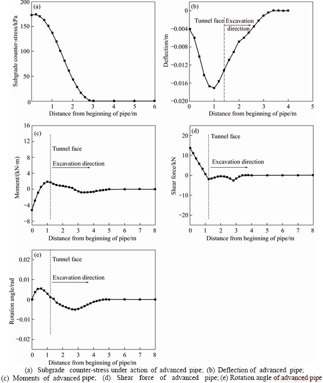
Figure 2 Advanced pipe reactions using Winkler model:
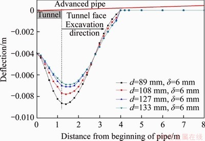
Figure 3 Deflection curves of different pipe roof diameters (d and �� represent the diameter and thickness of the pipe, respectively)

Figure 4 Pipe deflection curve under different initial deflection
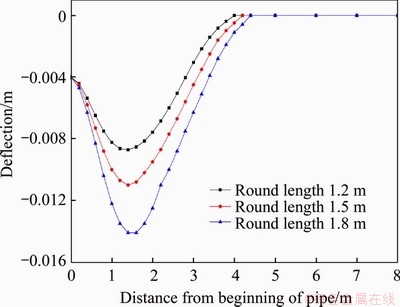
Figure 5 Pipe deflection curve of different round lengths
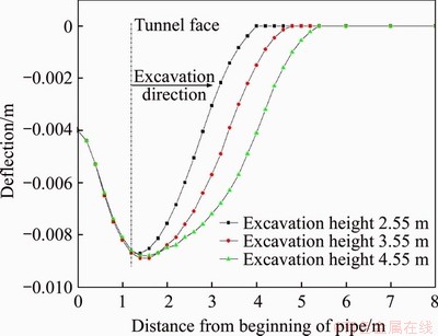
Figure 6 Pipe deflection curve of different excavation heights
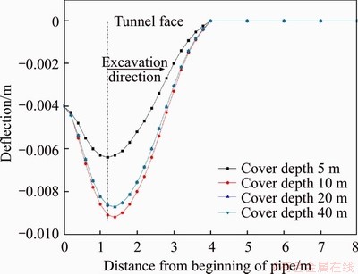
Figure 7 Pipe deflection curve of different cover depths
4.6 Influence of rock internal friction angle
As shown in Figure 8, the pipe deflection decreases with the increase of internal friction angle and the gradient decreases. It shows that the better the surrounding rock condition is, the greater the internal friction angle is, the closer the point is to the tunnel face, whose deflection value is equal to 0. Horizontal projection lengths of the fracture surface are 1.957, 1.625, 1.327 and 1.056 m when the internal friction angle is 15��, 25��, 35�� and 45��, respectively. This shows that the horizontal projection length of the fracture surface decreases with the increase of the internal friction angle, and it is also the reason why the point, whose deflection value is equal to 0, is closer to the tunnel face.
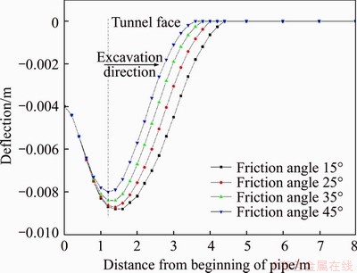
Figure 8 Pipe roof deflection curve of different internal friction angle
5 Influence of different factors on stability of tunnel face
5.1 Influence of rock cohesion
As shown in Figure 9, the cohesion is proportional to the safety factor of the tunnel face. When the cohesion is very small, the safety factor of different round length has little difference, but it is less than 1 and unstable. So when the cohesion of surrounding rock is very small, besides shortening round length, reinforcement measures should be taken to ensure the stability of the tunnel face. With the increase of cohesion, the safety factor of different round length increases gradually, and the smaller the round length is, the safer it is.

Figure 9 Influence of cohesive on stability
5.2 Influence of rock internal friction angle
As shown in Figure 10, the safety factor of tunnel face increases with the increase of internal friction angle, and the smaller the round length is, the more stable it is. With the increase of internal friction angle, the slope of sliding surface increases and the length of fracture surface decreases. The horizontal projection length of the fracture surface decreases gradually, which indirectly leads to the reduction of foundation reaction and rock mass on the fracture surface. The increased slope of sliding surface reduces the safety factor of the tunnel face, while the reduction of foundation reaction and rock mass on the fracture surface increases the safety factor of the tunnel face and the increase is greater than the former, so the larger the angle of internal friction is, the more stable the tunnel face is.
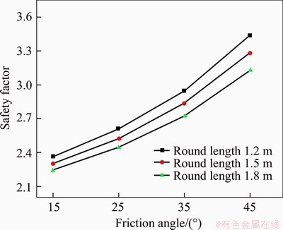
Figure 10 Influence of internal friction angle on stability
5.3 Influence of tunnel cover depth
Figure 11 shows, the influence of cover depth on the tunnel face stability. The smaller the round length is, the greater the safety factor of the face of the tunnel face is. When the cover depth is less than 10 m, the safety factor of the tunnel face decreases with the increase of the cover depth. After 10 m, the safety factor of the tunnel face increases first, and then remains unchanged. The reason is the influence of the cover depth on the disturbance of the pipe roof.
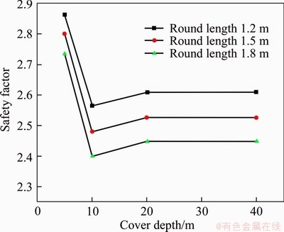
Figure 11 Influence of cover depth on stability
5.4 Influence of excavation height
As shown in Figure 12, the safety factor of tunnel face stability decreases with the increase of excavation height. The smaller the excavation height is, the greater the influence of the round length on the safety factor is. With the increase of the excavation height, the influence of the round length on the safety factor becomes smaller. With the increase of excavation height, the length of fracture surface increases, which leads to the increase of anti-sliding force. The horizontal projection of the fracture surface increases gradually, which leads to the increase of the foundation reaction and the rock mass on the fracture surface. The increased anti-sliding force increases the safety factor of the tunnel face, while the increased foundation reaction and the rock mass on the fracture surface decreases the safety factor of the tunnel face and decreases more than the former, so the larger the excavation height is, the more unstable the tunnel face is.
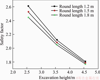
Figure 12 Influence of excavation height on stability
5.5 Influence of initial deflection at beginning of advanced pipe
As shown in Figure 13, the safety factor decreases with the increase of the initial deflection of the pipe. The smaller the initial deflection of the pipe, the greater the influence of the round length on the safety factor. With the increase of the initial deflection of the pipe roof, the influence of the round length on the stability safety factor becomes smaller. Foundation reaction increases with the increase of initial deflection, because the rupture angle is greater than 45��. The larger the initial deflection is, the more unstable the tunnel face is.
6 Three-dimensional numerical simulation
6.1 Numerical model and parameters
The numerical simulation model, as shown in Figure 14, is established with a range of 60 m��80 m��40 m. The tunnel cover depth is 40 m, and the round length is 1.2 m. The advanced pipes are simulated with beam elements, and the grouting reinforcement is conducted through increasing the rock mechanical parameters. For example, modulus, cohesion, and friction angle of the reinforcement zone is larger than the initial rock. Parameter of surrounding rock and support material are shown in Table 1.
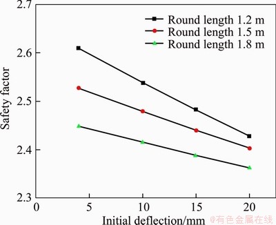
Figure 13 Influence of initial deflection on stability
6.2 Influence of advanced pipe length
The whole deformation of the tunnel face under the advanced pipe with different length is shown in Figure 15 and the horizontal displacement at the central line of tunnel face is shown in Figure 16. On the whole, the deformation at the center of the tunnel face is larger than the deformation at the surround sides and at the corner. The horizontal displacement varies a little with the increasing of the pipe length. When the pipe length is 4 m, the horizontal displacement at the central of the tunnel face is the biggest, and the number is 6.8 mm. When the pipe length is 5 m, the horizontal displacement decreases, and the number is 6.3 mm.

Figure 14 Numerical model:
Table 1 Parameter of surrounding rock and support material
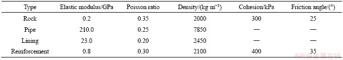

Figure 15 Deformation contour of tunnel face under different pipe lengths (Unit: mm):
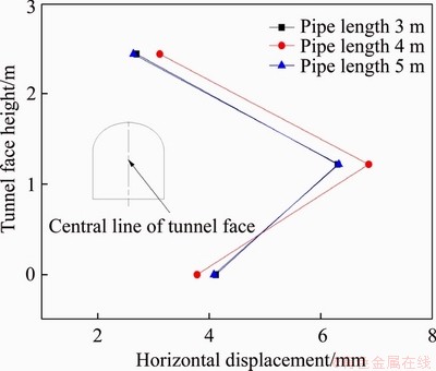
Figure 16 Horizontal displacement at central line of tunnel face under different pipe lengths
6.3 Influence of ring spacing of advanced pipe
The whole deformation of the tunnel face under the advanced pipe with different ring spacing is shown in Figure 17 and the horizontal displacement at the central line of tunnel face is shown in Figure 18. The horizontal displacement at the center of the tunnel face increases with the increase of the pipe ring spacing. When the pipe ring spacing is 0.3 m, the horizontal displacement at the central of the tunnel face is the biggest, and the number is 6.3 mm. When the pipe ring spacing is 0.4 m, the horizontal displacement increases, and the number is 6.8 mm.
6.4 Influence of longitudinal spacing of advanced pipe
The whole deformation of the tunnel face under the advanced pipe with different longitudinal spacing is shown in Figure 19 and the horizontal displacement at the central line of tunnel face is shown in Figure 20. The horizontal displacement at the center of the tunnel face increases with the increase of the pipe longitudinal spacing. When the pipe longitudinal spacing is 1.8 m, the horizontal displacement at the central of the tunnel face is the biggest, and the number is 6.3 mm. When the pipe longitudinal spacing is 2.4 m, the horizontal displacement decreases, and the number is 6.8 mm.
6.5 Influence of external angle of advanced pipe
The whole deformation of the tunnel face under the advanced pipe with different external angle is shown in Figure 21, and the horizontal displacement at the central line of tunnel face is shown in Figure 22. The displacements in the central zone are larger than those in tunnel face surroundings. Furthermore, the maximum horizontal displacement of the point P, at the center of the tunnel face, with the external angle of the advanced pipe, is shown in Figure 23. When the external angle of the advanced pipe is 35��, the horizontal displacement is the minimum. This may be related with pipes bearing part of the surrounding rock pressure. Therefore, there is an optimum external angle. As for this engineering, the optimum angle is 35��.
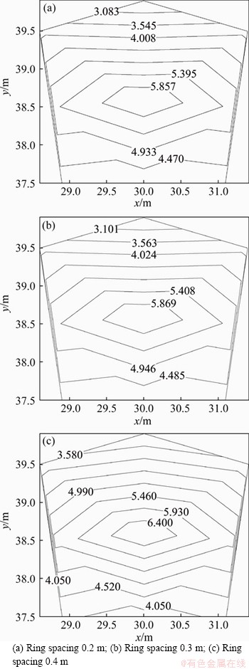
Figure 17 Deformation contour of tunnel face under different ring spacings of advanced pipes (Units: mm):

Figure 18 Horizontal displacement at central line of tunnel face under different ring spacings of advanced pipes
7 Results and discussions
The stability of the tunnel face without the support of the pipe roof is calculated to be 0.809. After the application of the pipe roof, the stability of the tunnel face meets the requirements, so the application of the pipe roof can improve the stability of the tunnel face.
The ground subgrade reaction near the tunnel face is larger than the surrounding rock pressure, and gradually decreases when it is far from the tunnel face of the excavation. This is agreed well with the model test in Ref. [16]. The maximum deflection of the pipe appears near the tunnel face. In the excavation section, the shear force decreases gradually. It increases first and then decreases due to the influence of foundation reaction.
The deflection of pipe roof decreases with the increase of pipe roof diameter, but the gradient decreases slightly. The maximum deflection of pipe increases with the increase of initial deflection. The pipe deflection increases with the increase of tunnel round length. In front of the tunnel face, the deflection increases with the increase of tunnel excavation height. All these are in good accordance with Ref. [17]. The pipe deflection does not increase with the increase of tunnel cover depth, but has an extreme value, due to the rock pressure calculated by the China Road Tunnel Design Code. The pipe deflection decreases with the increase of internal friction angle.
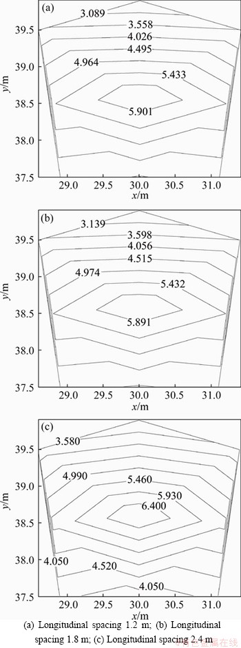
Figure 19 Deformation contour of tunnel face under different longitudinal spacings of advanced pipes(Units: mm):
The safety factor of the tunnel face is proportional to the rock cohesion. The safety factor of tunnel face increases with the increase of internal friction angle, and the smaller the round length is, the more stable it is. When the cover depth is less than 10 m, the safety factor of the tunnel face decreases with the increase of the cover depth. After 10 m, the safety factor of the tunnel face increases first, and then remains unchanged. The reason is the influence of the cover depth on the disturbance of the pipe roof. The safety factor of tunnel face stability decreases with the increase of excavation height. The safety factor decreases with the increase of the initial deflection of the pipe.
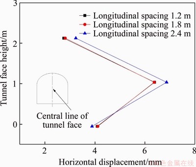
Figure 20 Horizontal displacement at central line of tunnel face under different horizontal spacings of advanced pipes
The horizontal displacement varies a little with the increasing of the pipe length. The horizontal displacement at the center of the tunnel face increases with the increase of the pipe ring spacing. The horizontal displacement at the center of the tunnel face increases with the increase of the pipe longitudinal spacing. When the external angle of the advanced pipe is 35�㣬the horizontal displacement at the center of the tunnel face, the point P, is the minimum.
8 Conclusions
1) Several factors were investigated to elucidate their effect on the maximum deflection of the pipe roof, the displacement near the tunnel face and the safety factor of the tunnel face. The results suggest that when the diameter of the pipe roof and the internal friction angle increase, or the seat displacement, the excavation footage and the height of the excavation step decrease, the maximum deflection of the pipe roof and the displacement near the tunnel face will decrease, and the safety factor of the tunnel face will increase. Measures can be taken from the above aspects to improve the stability of the tunnel face and reduce the displacement of the tunnel face, such as shortening the excavation round length and reducing the excavation height.

Figure 21 Deformation contour of tunnel face under different external angles of advanced pipes(Unit: mm):
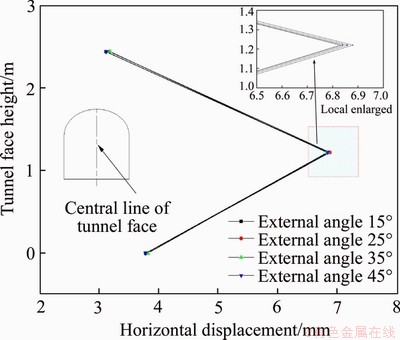
Figure 22 Horizontal displacement at central line of tunnel face under different external angles of advanced pipes
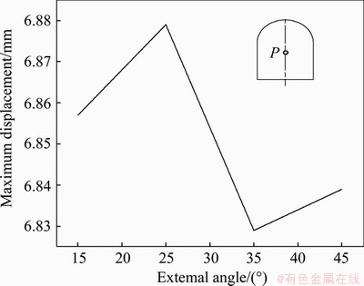
Figure 23 Maximum horizontal displacement vs external angle of advanced pipes
2) The pipe deflection does not increase with the increase of tunnel cover depth, but has an extreme value. For the safety factor of the tunnel face, there is also an extreme value. This is related to the calculation method of surrounding rock pressure adopted in the Chinese Tunnel Design Code.
3) If the cohesion of surrounding rock is very small, only shortening the round length can not meet the stability of the tunnel face. So the surrounding rock should be strengthened or core soil should be retained.
4) In high cohesive surrounding rock, high internal friction angle surrounding rock, smaller excavation height and smaller pipe roof support seat move down, which can reflect the effect of short round length on safety factor.
5) On the whole, the deformation at the center of the tunnel face is larger than the deformation at the surround sides and at the corner. The horizontal displacement varies little with the increasing of the pipe length. The horizontal displacement at the center of the tunnel face increases with the increase of the pipe ring spacing and the pipe longitudinal spacing. There is an optimum external angle. As for this engineering, the optimum angle is 35��.
Contributors
AN Yong-lin provided the concept and edited the draft of manuscript. ZHOU Jin and OUYANG Peng-bo conducted the literature review and wrote the first draft of the manuscript. AN Yong-lin and LI Jia-hao edited the draft of manuscript. All authors replied to reviewers�� comments and revised the final version.
Conflict of interest
AN Yong-lin, ZHOU Jin, OUYANG Peng-bo, and LI Jia-hao declare that they have no conflict of interest.
References
[1] LYU H M, SHEN S L, ZHOU A N, CHEN K L. Calculation of pressure on the shallow-buried twin-tunnel in layered strata [J]. Tunnelling and Underground Space Technology, 2020, 103: 103465. DOI: org/10.1016/j.tust.2020.103465.
[2] LYU H M, SUN W J, SHEN S L, ZHOU A N. Risk assessment using a new consulting process in fuzzy AHP [J]. Journal of Construction Engineering and Management, 2020, 146(3): 1-12. DOI: 10.1061/(ASCE)CO.1943-7862.00017 57.
[3] HISATAKE M, OHNO S. Effects of pipe roof supports and the excavation method on the displacements above a tunnel face [J]. Tunnelling and Underground Space Technology, 2008, 23: 120-127. DOI: 10.1016/j.tust.2007.02.002.
[4] HU Y F, DONG X P, MA X L, CHE G Z. Analysis on face stability of shallow buried tunnel in weak formation during its construction [J]. Chinese Journal of Underground Space and Engineering, 2013, 9(6): 1368-1373.
[5] HUANG P M, KONG H, WANG M S. Effect of keeping core soil on stability of tunnel working face [J]. Chinese Journal of Rock Mechanics and Engineering, 2005, 24(3): 521-525.
[6] XIAO G Z, WEI X L. Introduction to ADECO-RS tunneling method of Italy [J]. Modern Tunnelling Technology, 2007, 44(3): 11-15. DOI: 10.13807/j. cnki.mtt.2007.03.003. (in Chinese)
[7] SALVADOR S, CONGKE Y, RAFAEL J. An upper bound solution for tunnel face stability analysis considering the free span [J]. Tunnelling and Underground Space Technology, 2020, 103: 103375. DOI: org/10.1016/j.tust.2020.103515.
[8] NOMIKOS P P, SOFIANOS A I, TSOUTRELIS C E. Symmetric wedge in the roof of a tunnel excavated in an inclined stress field [J]. International Journal of Rock Mechanics and Mining Sciences, 2002, 39(1): 59-67. DOI: 10.1016/S1365-1609(02)00013-8.
[9] BILOTTA E, TAYLOR R N. Centrifuge modelling of tunnelling close to a diaphragm wall [J]. International Journal of Physical Modelling in Geotechnics, 2005(1): 27-41. DOI: 10.1680/ijpmg.2005.050103.
[10] YASLETTY Z H, ALDO D F, ANDRE P A. Three-dimensional analysis of excavation face stability of shallow tunnels [J]. Tunnelling and Underground Space Technology, 2019, 92: 103062. DOI: org/10.1016/j.tust.2019. 103062.
[11] AN Y L, LI J H, CAO Q, YUE J, OUYANG P B. Influence of excavation footage on tunnel face stability using limit analysis [J]. Journal of Railway Science and Engineering, 2019, 16(2): 443-449. DOI: 10.19713/j.cnki.43-1423/u. 2019.02.021. (in Chinese)
[12] AN Y L, LI J H, CAO Q, YUE J, OUYANG P B. Analysis of tunnel face stability in soft-hard ground layers [J]. China Railway Science, 2019, 40(1): 79-87. DOI: 10.3969/j.issn. 1001-4632.2019.01.11. (in Chinese)
[13] CANG S D. Research on pre-brace mechanism of pipe umbreila method [D]. Chengdu: Southwest Jiaotong University, 1998. (in Chinese)
[14] GU L. Principle of roof supporting tube and interruption of excavating deduced by water penetration in thin soft rock layer under water [D]. Changsha: Central South University, 2010. (in Chinese)
[15] WANG H T. Research on mechanism of pipe roof reinforcement and tunnel face stability [D]. Dalian: Dalian University of Technology, 2009. (in Chinese)
[16] SHIN J H, CHOI Y K, KWDN O Y, LEE S D. Model testing for pipe-reinforced tunnel heading in a granular soil [J]. Tunnelling and Underground Space Technology, 2008, 23: 241-250. DOI: 10.1016/j.tust.2007. 04.012.
[17] DING Z D, FU J, LIU X F, HUANG J. Study of mechanical model for pipe roof in talus tunnel considering spatial effect [J]. Journal of the China Railway Society, 2018, 40(7): 121-127. DOI: 10.3969/j.issn.1001-8360.2018.07.018. (in Chinese)
(Edited by HE Yun-bin)
���ĵ���
��ǰ֧��������������ȶ��Է���
ժҪ�������������ȶ�������ʩ������Ҫ���ݡ������¿˶��ػ�ģ�ͺ��弫��ƽ�ⷨ���Գ�ǰС�����µ�����������Χ���ȶ��Խ����˷�������ͨ����ֵģ�⣬����������������������������������˸������Թ����ӶȺ��������ȶ��Ե�Ӱ�졣�������������С���ܵĹܾ�����СС����֧�����ij�ʼλ�ƣ����ö̽��ߡ�С���ڸ߶ȿ������������ȶ��ԡ�����������������ӣ��������ȶ���ȫϵ���ȼ�С������Ȼ�ֲ��䡣�������������ĵı����������ܱߺ�ת�Ǵ��ı�������ˮƽλ����ܳ������ӱ仯�������������ĵ�ˮƽλ�����Źܻ����ܳ������������������ǰС���ܴ���һ�����ŵ����Ƕȡ�
�ؼ��ʣ������������ȶ��ԣ���ǰС���ܣ��¿˶��ػ�ģ�ͣ���ֵģ��
Foundation item: Project(20A187) supported by the Hunan Provincial Department of Education, China; Projects(51408216, 51308209) supported by the National Natural Science Foundation of China
Received date: 2020-06-28; Accepted date: 2020-10-28
Corresponding author: AN Yong-lin, PhD, Associate Professor; Tel: +86-13203116711; E-mail: aylcsu@163.com; ORCID: https:// orcid.org/0000-0002-4250-427X
Abstract: To keep the tunnel face stable is very important for tunnel construction. In this paper, the tunnel face stability under the advanced pipe was analyzed using the Winkler foundation model and rigid limit equilibrium. The tunnel face deformation characteristics were also analyzed using the numerical simulation. The influence of parameters on the deflection of the pipe roof and the stability of the tunnel face were discussed. The results show that the tunnel face stability can be improved through increasing the pipe diameter, decreasing the initial displacement at the beginning of the pipe seat, and adopting the short round length and small excavation height. With the increase of tunnel burial depth, the safety factor of tunnel face stability first decreases, then increases, and then remains unchanged. The deformation at the center of the tunnel face is larger than the deformation at the surround sides and at the corner. The horizontal displacement varies little with the increasing of the pipe length. The horizontal displacement at the center of the tunnel face increases with the increase of the pipe ring spacing and the pipe longitudinal spacing. There is an optimum external angle.
