

Application of new VBHF optimization strategy to improve formability of automobile panels with aluminum alloy sheet
WANG Wu-rong(������)1, CHEN Guan-long(�¹���)1, LIN Zhong-qin(������)1, 2
1. School of Materials Science and Engineering, Shanghai University, Shanghai 200072, China;
2. Shanghai Key Laboratory of Digital Autobody Engineering, School of Mechanical Engineering,
Shanghai Jiao Tong University, Shanghai 200240, China;
3. State Key Laboratory of Mechanical System and Vibration, Shanghai Jiao Tong University, Shanghai 200240, China
Received 9 December 2008; accepted 25 March 2009
Abstract:
A VBHF (Variable Blank Holder Force) optimization strategy was employed to determine the optimal time-variable and spatial-variable BHF trajectories, aiming at improving the formability of automobile panels with aluminum alloy sheet. The strategy was implemented based on adaptive simulation to calculate the critical wrinkling BHF for each segmented binder of the Numisheet��05 deck lid in a single round of simulation. The thickness comparison of the stamped part under optimal VBHF and constant BHF shows that the variance of the four sections is decreased by 70%, 44%, 64% and 61%, respectively, which indicates significant improvement in thickness distribution and variation control. The investigation through strain path comparison reveals the fundamental reason of formability improvement. The study proves the applicability of the new VBHF optimization strategy to complex parts with aluminum alloy sheet.
Key words:
deep drawing; variable blank holder force; aluminum alloy sheet; formability;
1 Introduction
Wrinkling and cracking are two key surface issues for deep drawing parts, besides which there are other product quality requirements including uniform thickness, strain distortion, springback, etc. Engineers and researchers would normally try to regulate one or several of the process parameters such as initial blank contour, friction condition, drawbead resistance and blank holder force (BHF, FBH)[1-4] to achieve successful drawing parts free of above defects.
In terms of BHF regulation, time-variable and spatial-variable BHFs occur in industrial deep drawing process, but typically not in an optimal manner[5]. Researchers started to build system for improving the application of variable blank holder force (VBHF) to reduce the work load associating with die surface grinding and cushion shimming. The first system established by HARDT and LEE[6] was designed to maintain a constant amount of buckling in unsupported region of the part. This work was continued by HARDT and FENN[7], who employed closed-loop control of sheet forming operation to determine optimal BHF trajectories. SIEGERT[8] designed a blank holder made up of rigid segmented sections, providing independent control over the material.
With the availability of VBHF press, researchers continued to conduct in-depth study to develop optimization strategy for regulating the BHF trajectories in terms of punch stroke. CAO et al presented PI (proportional�Cintegral)[9] and ARMA (Auto-Regressive and Moving Average)[10] method, which increased the part quality of conical cup and hemispherical cup, respectively. SUN et al[11] proposed an RSM model combined with the FEM simulation to increase the formability of aluminum sheet when being applied to a rectangular box. In work of SHENG et al[12], the adaptive simulation was used to predict the variable blank holder force in conical cup drawing. AYED et al[13] investigated the BHF optimization of Numisheet��99 front door panel with three inequality constraints.
In our previous research[14], a proportional-integral-derivative (PID) optimization strategy has been presented based on the analysis of BHF formability window and integrated into commercial FEM code to obtain time-variable and spatial-variable optimal BHF in a single round of forming simulation. Then, a stepped rectangular box of 60 mm in drawing height with 10 segmental binders was adopted. The constant BHF experiment and the derived trajectory of optimal BHF were verified on a multipoint variable BHF hydraulic press and the experiment results corresponded well with FEM optimization, which increased the drawing depth by 33%.
In this study, the above closed loop optimization strategy is applied to a complex automobile deck lid inner panel, which is the benchmark of Numisheet��05[15]. The primary goal is to design proper segmented binders for the drawing tool set and achieve time-variable BHF trajectories for each segmented binder. To verify the improvement of part quality, the thickness distribution and variation of stamped part under the optimal VBHF trajectories derived in this study are compared with those under constant BHF drawing published by Numisheet��05 Committee.
2 Quick review of Numisheet��05 deck lid benchmark and PID closed loop VBHF optimization strategy
The forming tools used in this benchmark are shown in Fig.1. The participators can use either physical drawbeads or line drawbeads in the forming simulation. The distributing information for the physical drawbead geometry is shown in Fig.2. The line drawbeads could save the calculation time by equivalent virtual resistance. However, the precision is inadequate as the line drawbeads model couldn��t truly simulate the material draw-in and draw-out at the drawbeads location. Therefore, in this study, physical drawbeads were chosen to simulate the drawbead behavior for high precision.
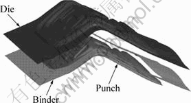
Fig.1 Forming tools used in Numisheet��05 rear deck lid benchmark
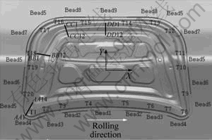
Fig.2 Drawbead centerlines, transition points, and coordinate system orientation, and thickness measurement locations of Numisheet��05 rear lid
The strategy developed in this work is based on the extended BHF formability window. Fig.3 shows three types of BHF formability windows representing three materials with different levels of deep drawing formability. The part will have cracking defect if the BHF is larger than cracking BHF value. While if the BHF is smaller than the wrinkling BHF, wrinkling will occur in the part. The area between the cracking BHF and the wrinkling BHF is the safety region. The required punching depth is denoted as the design target and intersection I tells the punching limit for the material. In Fig.3(a), the design target is smaller than the limit depth and the safety region is wide enough to contain constant BHF trajectory. Therefore, the part could be formed successfully by constant BHF or VBHF as long as they are in the scope of the safety region. In Fig.3(b), the safety region is limited so that constant BHF couldn��t form this part to the required depth. Under this circumstance, VBHF is a perfect choice to form this part. In Fig.3(c), the design target is larger than the limit depth of the material, which indicates that neither constant BHF nor VBHF could form this part to the required depth. Through these BHF formability windows, one can see that wrinkling BHF is the minimum BHF that could suppress the defect of wrinkling. In the meantime, the wrinkling BHF enables the maximum draw-in of sheet material during deep drawing, postponing the onset of necking and decreasing the possibility of cracking. Therefore, the wrinkling BHF is served as the optimal BHF trajectory in this study.
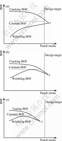
Fig.3 Extended BHF formability windows: (a) Feasible constant BNF window; (b) Feasible VBHF window; (c) Infeasible VBHF window
Fig.4 shows the flowchart of the BHF optimization strategy. The BHF is adjusted by PID controller at each optimization step so that the BHF is just large enough to avoid wrinkling. The optimization starts with an initial BHF. Then, wrinkling height (HW) will be calculated for each optimization step of forming simulation. If this wrinkling height is under the safe range of wrinkling (HW, S), then the current iterative BHF is the optimal BHF for the calculating step and will be treated as the initial BHF for the next optimization step. Otherwise, the wrinkling PID will be triggered to regulate the BHF so as to control wrinkling height under desired amplitude. The formula of wrinkling height PID controller is
![]() (1)
(1)
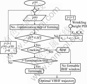
Fig.4 Flowchart of closed-loop PID control logic for VBHF optimization
where Kp, Ki and Kd are proportional, integral and differential gains of the wrinkling height PID controller; and e is the error between desired amplitude and current amplitude. They are updated at each iterative step as follows.
![]()
![]()
![]() (2)
(2)
Once the wrinkling is under control, the strategy will query the cracking index. If crack occurs, it tells the BHF that could suppress the wrinkling also causes the cracking. This indicates no formable BHF window of Fig.3(c) and the optimization stops. If no crack occurs, the optimization continues to calculate the next optimization step until the step reaches the termination. With this strategy, the time-variable VBHF trajectory for the whole punch stroke could be output for each segmented binder in a single round of the forming simulation.
For implementing this strategy, the important operation is to enable the plot of the optimization step and restart analysis. To get around this problem, the ��D3PLOT�� and ����D3DUMP��[16] output keywords have been implemented in the LS-Dyna input deck of the stamping simulation according to the optimization step set-up. At each optimization step, wrinkling height and cracking could be detected in D3PLOTnn plot and the BHF could be regulated according to the index level. Then, the input deck with updated BHF trajectory and D3DUMPnn could be submitted to LS-Dyna code for continuing calculation after the optimization step. With this implementation, the interaction between the strategy and the FEM code could be realized.
3 Determination of optimal VBHF trajectories for Numisheet��05 deck lid
3.1 Design of segmented binders
The purpose of BHF is to clamp the blank between the die and the blank holder piece, i.e., the binder tool. Both the drawbead and BHF have effect on the material flow and their influence is actually coupled. To solve this problem, the segmented binders are designed according to the drawbead setting and separated at the transition point of each drawbead. Accordingly, 11 pieces of segmented binders have been designed, as shown in Fig.5, which avoids the interference of conjunctional drawbeads.
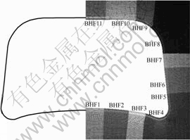
Fig.5 Design of segmented binders for deck lid
3.2 FEM modeling
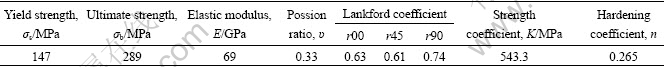
From Fig.2, it could be seen that this geometry is symmetrical by Y axis. Thus, only half of the tooling geometry is meshed in the simulation. Fig.6 shows the assembled FEM modeling for deep drawing. The physical drawbead has been modeled to simulate the true material draw-in and draw-out. The material used for this deck lid is a 0.9 mm AL 6111-T4 aluminum alloy. Table 1 lists its mechanical properties provided by Numisheet��05 Committee.
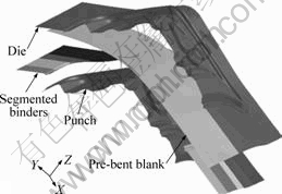
Fig.6 FEM modeling of rear lid using separated binders
Table 1 Mechanical properties of 6111-T4
3.3 Optimal BHF trajectories for segmented binders
The tool moving direction for this benchmark is: lower punch, stationary; die, moving down (-Z direction); and binder, moving down (-Z direction). The first step of optimization is to determine the BHF applied on each binder during binder closing. By using the optimization strategy in Fig.4, the BHF regulating on 11 pieces of segmented binders are listed in Table 2 along with the iterative steps. The gap between the binder and the die flange shows the wrinkling height of the black. After binder closing, the optimization enters into the second step, i.e., the forming step. Fig.7 shows derived VBHF trajectories for the 11 pieces of segmented binders. The forming limit diagram (FLD) has been widely used to assess sheet metal failure due to localized necking in sheet metal forming process. In this study, the FLD is also served as forming limit criterion and Fig. 8 shows the FLD under the VBHF trajectories. From Fig.8, the deck lid is free of cracking and wrinkling, which indicates that this part could be formed successfully under VBHF trajectories.
Table 2 Iteration of optimal BHF during binder closing
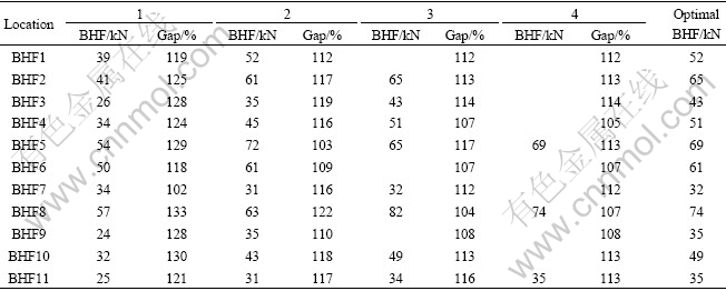
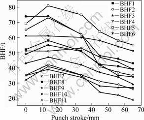
Fig.7 Optimal VBHF trajectories for deck lid
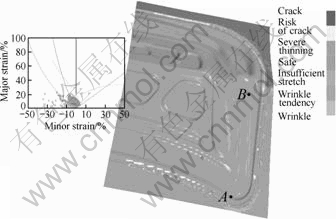
Fig.8 FLD of deck lid under optimal VBHF
4 Result comparison and discussionIn Numisheet��05 benchmark, constant BHF was used to form the deck lid. Thickness information of 50 points along AA, BB, CC and DD sections in Fig.2 has been provided. For comparison, the thickness has been measured for the same 50 points of the deck lid under the optimal VBHF trajectories. The thinning and variance have been compared for each section and listed in Tables 3-6.
Table 3 Thickness comparison along AA section between VBHF and constant BHF
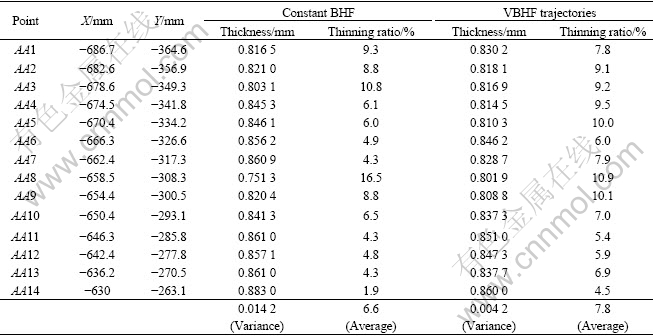
Table 4 Thickness comparison along BB section between VBHF and constant BHF
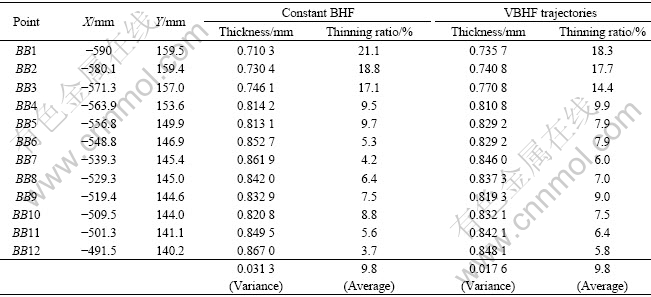
Table 5 Thickness comparison along CC section between VBHF and constant BHF
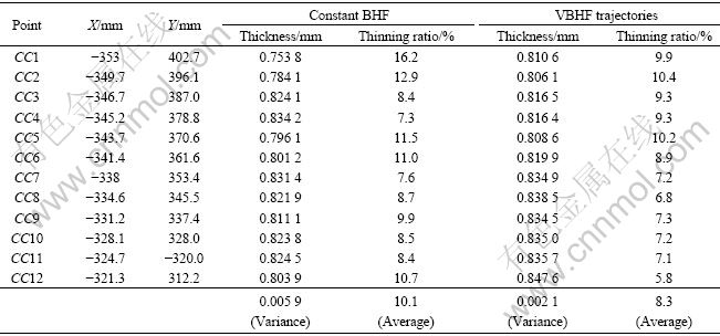
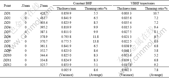
Table 6 Thickness comparison along DD section between VBHF and constant BHF
For fourteen points along AA section, the maximum thinning ratio under constant BHF and VBHF is 16.5% and 10.9%, respectively. The variation under VBHF is decreased by 70%, which is much less than that under constant BHF.
For twelve points of BB section, the maximum thinning ratio under constant BHF and VBHF is 21.1% and 18.3%, respectively. The average thinning are the same. The variation under VBHF is decreased by 40% and the uniformity of thickness distribution under VBHF is better than that under constant BHF.
For CC section and DD section, the maximum thinning ratio under VBHF is decreased by 5.1% and 5.2% compared with that under constant BHF. The variation under VBHF is decreased by 64% and 61% for CC section and DD section, respectively. The thickness variation also shows improvement with VBHF trajectories.
From above, three conclusions could be drawn: 1) For all the four sections, the maximum thinning of simulated part under constant BHF is higher than that under VBHF trajectories. This indicates that the necking is postponed effectively with VBHF; 2) The average thickness of four sections is basically the same; 3) When using VBHF, the variation of thickness is much smaller uniformity of thickness in the stamped part, which reduces the thickness variation significantly.
To analyze the effect of VBHF on the part thickness distribution, the strain paths of two dangerous locations (referring A, B in Fig.8) have been extracted from the simulation and illustrated in Fig.9. Both strain paths of location A and location B under the constant BHF are nearer to the region of double stretch than those under the VBHF. When the material is under double stretch, the plastic deformation is limited to the fixed area and the forming could only be realized by area expansion. Therefore, material under double stretch has larger tendency in thinning, like locations A and B under constant BHF. This indicates that wrinkling VBHF postpones the double stretch of the part, which decreases the maximum thinning and increases the uniformity of part thickness.
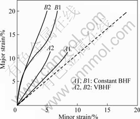
Fig.9 Strain paths of locations A and B
In the future works, the authors would like to extend the current study to decrease the number of binder segments, result of which will cut down the number of independent controllers used in the VBHF press and make it possible to move into the actual production.
5 Conclusions1) The new PID closed loop BHF optimization strategy is applied to the rear deck lid inner panel of the Numisheet��05 benchmark. The strategy appears to be capable of optimizing time-variable and space-variable BHF for complex part.
2) The comparison of thickness distribution between optimal VBHF trajectories and constant BHF shows the proposed BHF optimization strategy could decrease the maximum thinning by 5.6%. In the meantime, the thickness variation is also decreased significantly. This indicates that the VBHF optimization strategy could improve the formability and manufacturing robustness of complex parts in the deep drawing of aluminum alloy sheet.
3) Though the VBHF forming has a long way to industry due to the press setup difficulty, it could lead to a simplification of the bead geometry in die construction as the metal feeding would be controlled throughout the die by blank holder force instead of restraining force within the bead.
References
[1] NACEUR H, GUO Y Q, BATOZ J L, LENOIR C K. Optimization of drawbead restraining forces and drawbead design in sheet metal forming process [J]. International Journal of Mechanical Sciences, 2001, 43: 2407-2434.
[2] HE S, WU X, HU S J. Formability improvement for TWB using drawbead design [J]. Society of Automotive Engineers Technical Publication, 2001: 2001-01-3091.
[3] WANG H, LI E, LI G Y. Optimization of drawbead design in sheet metal forming based on intelligent sampling by using response surface methodology [J]. Journal of Materials Processing Technology, 2008, 206: 45-55.
[4] WEI D, CUI Z, CHEN J. Optimization and tolerance prediction of sheet metal forming process using response surface model [J]. Computational Materials Science, 2008, 42: 228-233.
[5] THOMAS W, ALTAN T. Application of computer modeling in part, die, and process design for manufacturing of automotive stampings [J]. Steel Research, 1998, 69: 4-9.
[6] HARDT D, LEE C G Y. Closed-loop control of sheet metal stability during stamping [C]//The 13th North American Manufacturing Research Conference. Dearborn, MI, USA: Society of Manufacturing Engineers, 2000: 315-322.
[7] HARDT D, FENN R. Real-time control of sheet stability during Forming [J]. Journal of Engineering for Industry, 1993, 115: 299-308.
[8] SIEGERT K. Multipoint cushion systems for sheet metal forming presses [J]. The FABRI, 1999, 11: 82-86.
[9] CAO J, BOYCE M C. A predictive tool for delaying wrinkling and tearing failures in sheet metal forming [J]. ASME Journal of Engineering Materials and Technology, 1997, 119: 354-365.
[10] NEIL K, CAO J. Estimation of optimal blank holder force trajectories in segmented binders using an ARMA model [J]. ASME Journal of Manufacturing Science and Engineering, 2003, 125: 763-770.
[11] SUN C Z, CHEN G L, LIN Z Q. Determining the optimum variable blank-holder forces using adaptive response surface methodology (ARSM) [J]. International Journal of Advanced Manufacturing Technology, 2004, 26: 23-29.
[12] SHENG Z Q, JIRATHEARANAT S, ALTAN T. Adaptive FEM simulation for prediction of variable blank holder force in conical cup drawing [J]. International Journal of Machine Tools and Manufacture, 2004, 44: 487-494.
[13] AYED L B, DELAM?ZI?RE A, BATOZ J L. Optimization of the blank holder force distribution with application to the stamping of a car front door panel (Numisheet'99) [C]//The 6th International Conference and Workshop on Numisheet'05. MI, USA, 2005: 849-854.
[14] LIN Z Q, WANG W R, CHEN G L. A new strategy to optimize variable blank holder force towards improving the forming limits of aluminum sheet metal forming [J]. Journal of Materials Processing Technology, 2007, 183(2): 339-346.
[15] XU S, LANKER T, ZHANG J. Specification for BM1: Decklid inner panel [C]//The 6th International Conference and Workshop on Numisheet'05. MI, USA, American Institute of Physics, 2005: 1137-1149.
[16] Livermore Software Technology Corporation. LS-DYNA keyword user��s manual [M]. vol. 1, Version 971, California, Livermore.
Foundation item: Project(50934011) supported by the National Natural Science Foundation of China; Project(20080430085) supported by the China Postdoctoral Science Foundation
Corresponding author: WANG Wu-rong; Tel/Fax: +86-21-56331377; E-mail: wrwang@shu.edu.cn
DOI: 10.1016/S1003-6326(09)60164-3
