

J. Cent. South Univ. (2020) 27: 1557-1571
DOI: https://doi.org/10.1007/s11771-020-4390-2

Structure optimization and flow field simulation of plate type high speed on-off valve
WANG Xiao-jing(������), LI Wen-jie(���Ľ�), LI Chun-hui(���), PENG Yi-wen(������)
Key Laboratory of Advanced Manufacturing and Intelligent Technology of Ministry of Education, Harbin University of Science and Technology, Harbin 150080, China
 Central South University Press and Springer-Verlag GmbH Germany, part of Springer Nature 2020
Abstract:
There is a relatively complex flow state inside the high speed on-off valve, which often produces low pressure area and oil reflux in the high-speed opening and closing process of the spool, causing cavitation and vortex and other phenomena. These phenomena will affect the stability of the internal flow field of the plate valve and the flow characteristics of the high speed on-off valve. Aiming at the problems of small flow rate and instability of internal flow field, a new spool structure was designed. The flow field models of two-hole and three-hole plate spools with different openings were established, and software ANSYS Workbench was chosen to mesh the model. The standard k-�� turbulence model was selected for numerical simulation using FLUENT software. The pressure distribution and velocity distribution under the same pressure and different opening degree were obtained. The structure and parameters of the optimization model were also obtained. The stability analysis of flow field under different pressure was carried out. The results demonstrate that the three-hole spool has a similar flow field change with the two-hole spool, but it does not create a low pressure zone, and the three-hole spool can work stably at 2 MPa or less. This method improves the appearance of low pressure area and oil backflow in the process of high speed opening and closing of spool. The stability of flow field and the flow rate of high speed switch valve are improved. Finally, the products designed in this paper are compared with existing hydraulic valve products. The results show that the three-hole plate type high speed on-off valve designed in this paper maintains the stability of the internal flow field under the condition of 200 Hz and large opening degree, and realizes the increase of flow rate.
Key words:
high speed on-off valve; flow field simulation; pressure and flow characteristics��
Cite this article as:
WANG Xiao-jing, LI Wen-jie, LI Chun-hui, PENG Yi-wen. Structure optimization and flow field simulation of plate type high speed on-off valve [J]. Journal of Central South University, 2020, 27(5): 1557-1571.
DOI:https://dx.doi.org/https://doi.org/10.1007/s11771-020-4390-21 Introduction
The high speed on-off valve has the characteristics of simple structure, low price, strong anti-pollution ability, easy use and maintenance, low requirements for electronic control loops. It is especially suitable for digital control of electro- hydraulic systems in situations where accuracy is not critical and the working environment is harsh. In developed countries, it has been used in many aspects such as construction machinery, agricultural machinery, automobiles, etc [1-3]. The flow state of the fluid medium within the high speed on-off valve structure is very complex. Because of the high frequency vibration, its pressure and flow will change drastically during opening and closing. This often causes spool vibration, cavitation and fluid self-sustaining oscillations [4-6]. Due to the limitations of experimental conditions, the internal flow field is numerically simulated in combination with the structure of the high speed on-off valve. This can help analyze factors that affect the performance of the high speed on-off valve. At the same time, the static characteristics of the high speed on-off valve should be simulated and analyzed. This is of great significance for the quality improvement of the high speed on-off valve.
Over the years, domestic and foreign scholars have done a lot of research to improve the performance of the high speed on-off valve. This provides a large amount of data for further development and performance improvement of the high speed on-off valve. Research on high speed on-off valve is being carried out earlier in developed countries. The response time of existing products and research results is generally from a few ms to 10 ms. Only a few countries have a response time below 1 ms [7]. The Fuji Company in Japan [8] developed a two-position two-way the high speed on-off valve. Its maximum frequency is 50 Hz and the maximum flow is 8 L/min. The low flow rate limits the application of valves. LEATI et al [9] proposed a dynamic study of two different types of check valves. A plate valve was designed for the new high frequency oscillator pump. The new valve guaranteed stable volumetric efficiency up to 325 Hz in both low and high voltage operation, and the delay was effectively shortened. CAO et al [10] developed a new type of high speed on-off valve, and the spool of this valve adopted a cone valve and its structure was a one-way valve which used oil pressure instead of electromagnetic to drive when it was turned on, saving energy and protecting environment. TANG et al [11] discussed the steady-state wave dynamic compensation method of hydraulic control valve. DENG [12] optimized the design of hydraulic poppet valve through finite element analysis. BATDORFF [13] applied for a patent on the fast-acting fluid control valve. In the same year, another two-position three-way threaded cartridge valve was developed as a pilot stage. Many scholars have done a lot of research on flow field with moving boundary by using dynamic mesh technique. Using the dynamic mesh technique, FANG et al [14] analyzed the influence of hole depth and aperture on sealing characteristics and blowing heating characteristics. SRIKANTH et al [15] used a dynamic mesh technique to simulate the formation and development of vortex phenomenon in hydraulic valve flow field. The results of Childs�� study on the minimum hole and deep hole seals with the minimum leakage and optimal rotor dynamic characteristics were proved by MIGLIORINI [16] through dynamic mesh technique. CHILDS et al [17] discussed the significant influence of hole depth on pore seal friction factor, leakage amount and rotor dynamic coefficient. Taking the pressure regulating valve of wet friction clutch as the research object, GUO [18] studied the steady state model and transient model of fluid in the flow passage. Based on the dynamic mesh technique, he also analyzed the transient analysis of the flow field in the flow passage of the pressure regulating valve and the influence of the spool movement on the pressure, flow and temperature in the field. HE et al [19] simulated the opening process of tri-eccentric butterfly valve by using dynamic mesh technique. The transient distribution and variation rules of internal flow field characteristics such as vortex and internal flow at different opening degrees in the spool opening process are obtained. Aiming at the problem of submunitions separation, LI [20] solved the practical engineering problems by utilizing the advantages of dynamic mesh technique in multi-body separation flow field simulation.
Although these studies have made some progress in solving the problem of high frequency and high flow, the requirements for use cannot be satisfied. The existing high speed on-off valve products are mainly ball valves with small flow and rotary valves with life and process problems which have not been widely used in China. In this paper, the design of high speed on-off valve spool structure is improved, and a new type of plate type high speed on-off valve spool structure is designed based on the existing research status.
2 Structure optimization of plate type high speed on-off valve
2.1 Design of spool size
The spool has many structural forms. Slide valve, poppet valve, ball valve and plate valve are the most common spool structure, as shown in Figure 1.
This paper proposes a plate spool structure that can reduce the weight of the spool by opening a hole in the spool. The design of the spool accelerates the response speed and overcomes problems such as long spool strokes and leakage of the spool structure. At the same time, the pressure balance problem of the ball valve is solved, and the vibration and cavitation problem caused by the radial offset unbalance of the cone valve is also solved. This is the ideal spool construction for high speed on-off valve [21, 22].
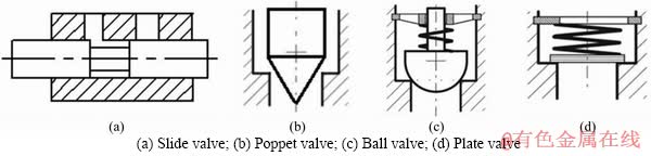
Figure 1 Common structure of spool:
This kind of plate type high speed on-off solenoid valve uses screw thread to connect the valve housing with the valve seat. Its spool is installed in the valve housing and seat. The inlet of the fluid is located in the valve seat and the outlet is located in the valve housing. In addition, the electromagnetic control mechanism is located inside the valve housing, which applies a force to the spool to control the oil passage between the inlet and outlet. This kind of plate type high speed on-off valve has a simple structure. By designing the plate spool structure and the arc three-hole structure, the problem of spool displacement caused by the unbalance of the spool in the prior art is solved. In order to reduce the weight of the plate spool, it is necessary to open a hole in the spool, which realizes the high speed on-off of the spool while ensuring a relatively large flow rate of the plate valve.
The overall model and section view of the plate valve are shown in Figure 2. Different types of plate valve spools have different fluid configure rations and flow areas, and their flow characteristics are also different. When designing the structure of the plate spool, larger flow area is not necessarily better, and its flow stability and resistance to cavitation should also be taken into account. In this paper, the spool structure of two-hole and three- hole is designed for analysis, and the structure with the best performance is selected by comparison.
The plate valve spool is attached to the valve seat by the reset spring, and the inlet is closed.
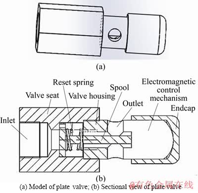
Figure 2 Overall model of plate valve:
When the electromagnetic control mechanism is electrified, the spool moves along the valve seat passage. This solves the problem of radial deviation caused by unbalanced force on the spool. When the inlet is opened, the oil enters the valve seat and the valve chamber of the valve casing through the two circular hole of the spool as shown in Figure 2, and flows out through the two outlets of the valve casing. When the electromagnetic control mechanism is de-energized, the spool closes the inlet under the action of the reset spring. The entire plate valve is compact, and the circular arc hole of the spool reduces the weight of the spool and enables quick opening and closing of the valve. The spool structure is shown in Figure 3.
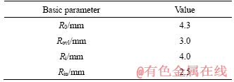
In this paper, two kinds of plate spool structure are designed referring to the runner size structure of Harway RK0 ball valve and other hydraulic valves. The diameter of the oil inlet is 8.6 mm; the diameter of the orifice is 5 mm; the diameter of the oil outlet is 8.6 mm; and the thickness of the spool is 1.5 mm. The spool sizes are shown in Figure 4, and its basic parameters are shown in Table 1.
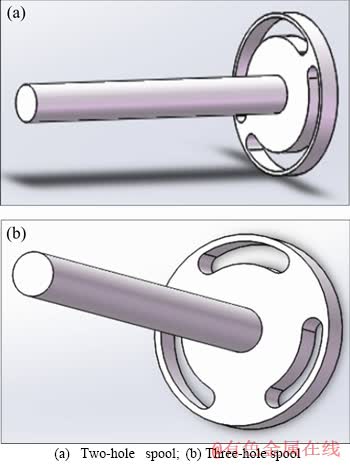
Figure 3 Structure of spool:
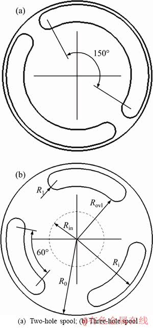
Figure 4 Related dimensions of spool:
2.2 Calculation of critical pressure
The spool structure designed in this paper will experience various flow conditions in the process of opening and closing the spool. Under different pressure, laminar flow and turbulent flow will occur in the oil flowing through the valve orifice. The flows involved in this paper are mainly rectangular gap flows. Therefore, the critical Reynolds number Rt of rectangular gap flow is adopted, as shown in Eq. (1):
 (1)
(1)
where Cd is the flow coefficient, 0.62; �� is the laminar flow coefficient, 0.157; �� is the oil density, 870 Kg/m3; �� is the viscosity, 2.784��10-2 Pa��s; and h is the opening degree; Rt=15.595; v=2.495��10-4/h m/s.
Table 1 Basic parameters of spool size
The flow rate of hydraulic oil can be expressed as Eq. (2):

 (2)
(2)
where Q is the flow rate, L/min; S1 and S2 are the cross-sectional areas of the inlet and outlet, respectively; v1 and v2 are the inlet and outlet flow rate, respectively, m/s.
Taking the turbulent critical flow velocity v as v2, the critical point flow rate Q=0.2352 L/min is calculated. When Q��0.2352 L/min, the oil is in a turbulent flow state. The critical point flow rate Q is substituted into Eq. (2), and v1=0.2 m/s is obtained.
The critical turbulent flow velocity v is taken as v2 to calculate the critical flow rate, which is immediately turbulence. Substitute the critical point flow Q into Eq. (2), and obtain v1=0.2 m/s.
According to Bernoulli equation, the relation between pressure difference and flow velocity can be obtained. The critical pressure (��Ptr) is obtained as Eq. (3):
 (3)
(3)
2.3 Establishment of flow equation
First, consider laminar flow with small pressure difference. In laminar flow state, two flow states are calculated according to the numerical relationship between the opening degree h and lovl, lovl=Rovl-Rin=0.5 mm.
When the spool opening degree is small, the opening gap between the spool and the valve chamber is small relative to the spool bore. It can be approximated as a gap flow between parallel plates, and the spool does not move in the radial direction. For the convenience of calculation, the internal flow field can be regarded as a differential pressure flow for calculation. The size is shown in Figure 5.
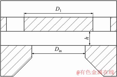
Figure 5 Internal dimensions of valve body
When the spool opening degree increases to a certain extent, the internal flow field structure of the plate type high speed on-off valve can be regarded as rectangular slot flow. The opening degree can be regarded as a rectangular channel with width of b and b>>h.
When the pressure increases, the internal flow field can easily reach the turbulent state. When the internal flow field is turbulent flow, the flow field of the valve orifice cross section can be regarded as the free flow from the thin-wall orifice.
The valve port flow equation is shown in Eq. (4):
 (4)
(4)
where h is the opening degree, mm; ��P is the inlet and outlet pressure difference, MPa; and ��Ptr is the critical pressure, MPa.
3 Establishment and meshing of 3D model of plate type high speed on-off valve flow field
3.1 Grid division
In practice, due to the influence of hydraulic power, shearing force and time-varying force during the working process of the plate valve, the distribution of the pressure and flow velocity of the valve spool is complicated. And it is difficult to obtain accurate theoretical calculation values for the flow rate. In this paper, the flow velocity and pressure of the spool are calculated by using computational fluid dynamics (CFD) technology, and the simulation results of the corresponding cross-section flow field are obtained, which provide a comparative reference value for theoretical calculation.
For complex engineering models, simplification is usually required. Retaining all the original details leads to too many grids. Improving the quality of the grid will also become difficult. Based on the above problems, the inlet and outlet flow channel should be appropriately simplified. The internal flow field model of the two-hole and three-hole opening degree of 0.2, 0.3, 0.4, 0.5, 0.6, 0.8, 1.0 and 1.2 mm was established by using SolidWorks software, respectively.
Meshing is an important part of the computer-aided engineering (CAE) simulation process. Usually the grid of the flow field is much denser than that of the structure field. The grid directly affects the solution accuracy, solution convergence and solution speed of the flow field [23, 24]. This paper selects the Mesh component of ANSYS Workbench for model division. The internal flow field model of the plate valve has a small opening degree of 0.1 mm. So, this paper uses unstructured to mesh it. In the position of arc notch, high pressure and high velocity, the mesh encryption is carried out to improve the calculation accuracy [25]. The boundary layer mesh is added to simulate the near wall flow field. The physical model of the internal flow field of the plate valve is imported into the Mesh component of the ANSYS Workbench for meshing. The number of boundary layer is set to 3 layers with a growth rate of 1.2. The meshing diagram of the flow field in the plate valve is shown in Figure 6. After inspection, the grid is of good quality and meets the calculation requirements [26].
Taking the plate type high speed on-off valve as the research object, the plate valve mesh model was introduced into the FLUENT software. There are many factors that affect the movement of high speed on-off valve. In order to reduce the influence of irrelevant factors on the high speed on-off valve movement, the following assumptions are made for the simulation of this plate valve model. First, the fluid medium is incompressible and it is a Newtonian fluid. Second, the internal flow field of the plate valve is well sealed and there is no leakage. Finally, the influence of friction on the spool is not considered, and the influence of temperature on the internal flow field is ignored.
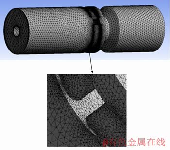
Figure 6 Flow field mesh model in plate valve
The divided mesh model is imported into FLUENT for simulation and calculation. Various flow inlet and outlet boundary conditions such as speed inlet, pressure inlet, mass flow inlet, and pressure outlet are provided in the software. In this paper, the inlet is designated as the pressure inlet, the outlet is the pressure outlet, and the other types are wall surfaces. The steady-state turbulence model based on standard k-�� turbulence model is selected, and the fluid medium is selected as 32# anti-wear hydraulic oil. The density of hydraulic oil is 870 kg/m3 and the viscosity is 2.784��10-2 Pa��s.
3.2 Numerical simulation calculation
In CFD, many physical quantities are stored on each grid. Any physical quantity on each grid will have a residual during the calculation iteration. This means that in one iteration, the same physical quantity has different computational residuals on different computational grids. In fact, in CFD calculation, each iteration step corresponds to only one residual. The residual in CFD has the maximum residual, average residual and root mean square residual. The root mean square residual is often used in CFD calculations.
The pressure and flow of the plate type high speed on-off valve are calculated by numerical simulation. Eight openings of 0.2, 0.3, 0.4, 0.5, 0.6, 0.8, 1.0 and 1.2 mm were selected for calculation and analysis. Set inlet pressure at 1 MPa and outlet pressure at 0. Initialization is performed iteratively. When the residual values of all variables, except the energy value, are lower than 10-3, it can be considered that the calculation meets the convergence requirements. In the residual curves shown in Figure 7, the abscissa represents the number of iterations of numerical calculation, and the ordinate represents the residual. It can be seen that the model meets the requirements.

Figure 7 Residual convergence curve
4 Pressure and flow characteristics of plate type high speed on-off valve
4.1 Pressure flow simulation of two-hole spool structure model
In this paper, the flow field simulation of the two-hole valve at the inlet pressure of 1 MPa and the outlet pressure of 0 is selected, and a section is taken for display the flow field pressure model. The opening degree of the two-hole spool structure is 0.2, 0.4, 0.6, 0.8, 1.0 and 1.2 mm, respectively. The total pressure distribution of the six groups is shown in Figure 8.
It can be seen from the pressure cloud diagram of Figure 8(a) that the opening degree of the two grooves is 0.2 mm. When the valve opening degree is small, the pressure distribution is uniform, and the pressure gradient is large only at the opening of the spool. As the opening degree increases, the pressure on the outlet side of the spool increases significantly, and a low pressure zone gradually appears on the outlet side of the spool. As shown in Figure 8(f), when the opening degree reaches 1.2 mm, a low pressure zone appears on the outlet side of the spool, indicating that cavitation is highly likely to occur here. The hydraulic forces received by the axial direction of the spool under different opening degree as shown in the simulation are shown in Table 2.
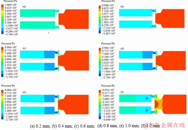
Figure 8 Pressure cloud diagram of two-hole plate valve with opening degree of:
Table 2 Steady-state hydraulic force of two-hole plate valve under different opening degrees
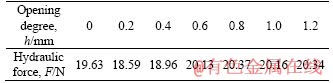
The liquid dynamic curve obtained by simulation is shown in Figure 9. When the valve port is closed, the spool is forced to a constant value of 19.63 N. In the initial stage of the spool opening, the contact area of the high pressure oil with the plate valve is increased, so the pressure is lower. As the opening degree increases, the pressure on the outlet side of the spool increases first and then decreases, and the pressure on the inlet side of the spool continues to increase. When the opening degree reaches about 0.8 mm, the spool tends to be stable.
It can be seen from Figure 10 that the flow velocity at the valve port is low, the oil at the valve port basically flows along the outer wall surface, and the flow is relatively stable. As the opening degree increases, the flow velocity also increases, and the flow velocity changes very significantly, and the distribution range also rapidly expands. When the opening degree reaches 0.4 mm, a significant vortex is generated due to the sudden expansion of the flow path, and the vortex range gradually increases as the opening degree increases. When the opening degree is increased to 0.8 mm, although the flow velocity distribution of the fluid in the flow field tends to be relatively stable, there is still a large vortex.
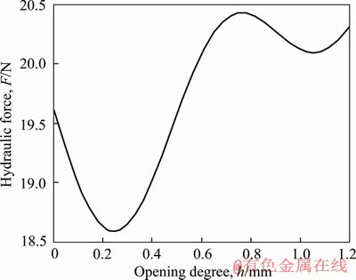
Figure 9 Curve of hydraulic dynamics of two-hole pool
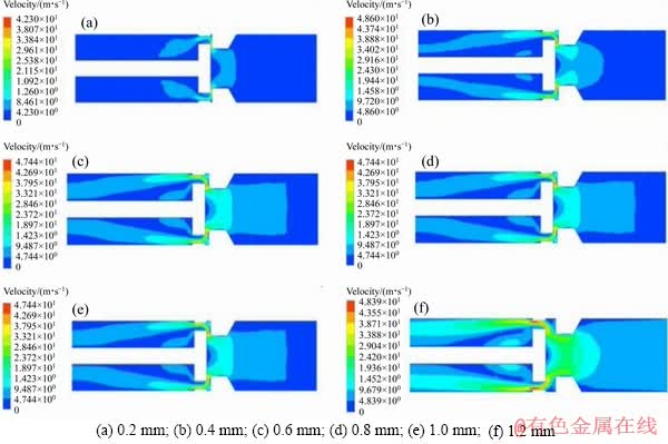
Figure 10 Velocity cloud diagram of two-hole plate valve:
When the spool is fully opened, the opening degree is 1.2 mm. The flow velocity in the flow channel reaches the highest, and the flow velocity is at the extension line of the jet angle, and gradually diffuses from the wall surface to the valve body cavity in the outlet port to generate a vortex. There are different flow states on both sides of the spool, so the steady-state hydrodynamic value distribution is also different. The extracted simulation traffic is shown in Table 3.
Table 3 Flow rate of two-hole plate valves with different opening degrees

It can be seen from the flow curve in Figure 11 that the flow velocity continues to increase as the opening degree increases. When the opening degree reaches 1.2 mm, the flow velocity reaches the maximum value of 24.8 L/min. The flow velocity increases first fast and then slowly.
4.2 Pressure flow simulation of three-hole spool structure model
A cross-section simulation result of a three-hole model with an inlet pressure of 1 MPa and an outlet pressure of 0 was selected. The three holes of the plate valve spool are symmetrically distributed by 120��, so the pressure distribution at the valve hole can be observed by selecting a pressure cloud of a section. As shown in Figure 12, a radial section pressure cloud diagram of fluid model with opening degree of 0.2, 0.4, 0.6, 0.8, 1.0 and 1.2 mm was selected for display, respectively.
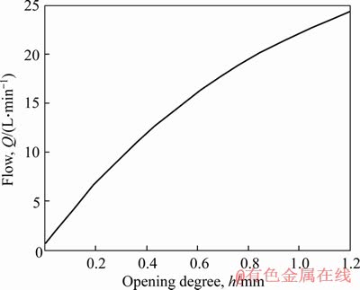
Figure 11 Flow curve of two-hole plate valve
As shown in Figure 12, when the opening degree is 0.2 mm, the flow field in the three-hole plate type high speed on-off valve is similar to that of the two-hole valve. The pressure distribution is uniform and the pressure difference is concentrated at the opening of the valve port. As the opening of the valve port increases, the pressure gradient gradually spreads to the orifice and the opening of the valve bore, which is similar to the two-hole opening. When the opening degree reaches the maximum, the pressure tends to be smooth and uniform.
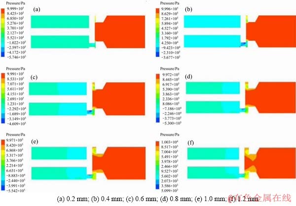
Figure 12 Pressure cloud diagram of three-hole plate valve with opening degree of:
Unlike the two-hole spool, the pressure change is relatively smooth throughout the spool opening process, and there is no low pressure zone and vortex. The flow state is smoother than the two-hole valve, and the cavitation and noise phenomena are smaller and less easy to occur. The hydraulic forces received by the axial direction of the spool under different opening degree as shown in the simulation are shown in Table 4.
As shown in Figure 13, when the opening degree is 0, the hydraulic power is a constant value of 19.63 N. As the opening degree of the spool increases, the growth trend is similar to that of the two-hole spool. When the valve port is opened, the pressure first decreases and then increases, and finally stabilizes at 0.6 mm. Compared with the two-hole spool, the pressure drop in the pre-opening of the three-hole spool is reduced, and the time required to reach a steady state is reduced. Its flow field is stable for a longer period of time. It is clear that the three-hole spool reacts more quickly and sensitively.
Table 4 Three-hole plate valve steady-state hydraulic force under different opening degrees based on CFD
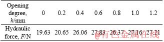
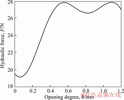
Figure 13 Curve of hydraulic dynamics of three-hole spool
It can be seen from Figure 14 that the flow velocity distribution state of the three-hole plate type high speed on-off valve is similar to that of the two-hole model. When the spool opening degree is small, the flow state is relatively stable. As the opening degree increases, the flow velocity increases rapidly. When the opening degree reaches 0.8 mm and 1.0 mm, as shown in Figures 14(d) and (e), a small vortex is generated in the flow path. When the spool is opened to 1.2 mm, the flow velocity in the flow path is highest and the vortex disappears. The flow velocity distribution in the three-hole spool flow channel is stable under different opening, and the vortex phenomenon is not obvious. The extracted simulation traffic is shown in Table 5.
The flow curve of the three-hole plate valve is drawn according to the extracted data as shown in Figure 15. It can be seen from the curve that as the opening degree increases, the flow velocity change trend is similar to that of the two-hole. As the opening degree increases, the flow velocity gradually increases and then decreases. The flow velocity is small due to its small flow area, and the flow velocity under the same opening degree is slightly smaller than that of the two-hole plate valve.
Comparing the pressure and flow simulations of the two-hole and three-hole models, the three-hole model is more stable. The three-hole model is slightly smaller in flow than the two-hole model, but its stability is much better than the two-hole model. And the three-hole model stable opening degree is larger, can be greater than 1.0 mm. The larger the opening degree is, the larger the flow is.
This makes up for the fact that the flow rate of the three-hole model is slightly smaller than that of the two-hole model. Compared with the two-hole model, the three-hole model has a large flow loss, but the three-hole spool valve model is less easy to cavitation and noise, and the spool wears less and the service life is longer. Therefore, the working condition of the three-hole spool structure is more ideal.
Figure 14 Velocity cloud diagram of three-hole plate valve at opening degree of:
Table 5 Flow rate of three-hole plate valve under different opening degrees based on CFD


Figure 15 Flow curve of two-hole plate valve
4.3 Stability of flow field model of three-hole plate type high speed on-off valve under different pressure
It can be seen from the above that the spool of the three-hole plate valve is more stable in pressure and flow velocity distribution under different opening degrees than the spool of the two-hole plate valve, and meets the optimization design requirements. Based on the three-hole spool, the static distribution of pressure and flow at different inlet and outlet pressure at the same opening degree is further studied, and the stability is observed. A three-hole plate valve model with an opening degree of 1 mm is taken, and the outlet pressure is taken to be 0. The pressure and flow simulations under different inlet and outlet pressure at the same opening degree are carried out under different pressure of 0.5, 1.0, 1.5, 2.0, 2.5 and 3.0 MPa, as shown in Figures 16 and 17.
As shown in Figure 16, the pressure differential is concentrated at the spool opening and the plate valve opening. With the increase of the pressure difference between the inlet and outlet, before the pressure reaches 2 MPa, the overall pressure distribution of the internal flow field model is stable, and the pressure difference between the inlet and outlet of the flow field has little effect on the pressure distribution. When the pressure reaches 2.5 MPa, a low pressure zone is created on the outlet side of the plate valve spool. As the pressure increases, the low pressure zone gradually expands. Therefore, the fluid model may cause instability such as cavitation. Of course, the low pressure zone here is relatively weak, so the internal flow field is relatively stable under different pressures.
It can be seen from Figure 17 that the change of pressure does not have a significant influence on the flow field in the three-hole plate type high speed on-off valve, and no significant vortex phenomenon is generated. It can be considered that the flow field in the three-hole plate type high speed on-off valve is stable under a working pressure of 3 MPa at an opening degree of 1 mm.
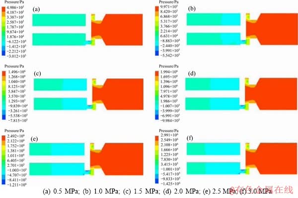
Figure 16 Pressure distribution of three-hole plate valve at:
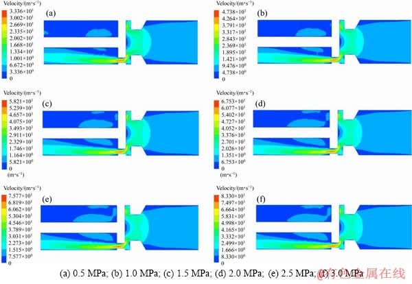
Figure 17 Flow velocity distribution of three-holes plate valve at:
5 Data comparison analysis
Flow rate is an important index to evaluate the performance of plate type high speed on-off valve, which is related to its work efficiency and application. According to the curve integral of two groups of flow simulation data of spool opening process and closing process, the flow rate of three-orifice valve can be obtained as Q=15.756 L/min.
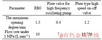
In order to further study the working performance of three-hole plate type high speed on-off valve, the RB0 ball valve structure produced by Harway company and the plate valve structure developed by Linz University which can work stably at 200 Hz and is suitable for high-frequency shock pump were selected for data comparison and analysis. According to the valve samples and the paper, two types of valves can be obtained, as shown in Figures 18 and 19. The parameter pairs are shown in Table 6.
By comparing the opening degree and flow data of three kinds of valves, it can be seen that the plate type high speed on-off valve with similar size and opening degree can realize higher flow rate under the same pressure condition. Similarly, for similar size and the same frequency under the work of high frequency shock pump plate valve, plate type high speed on-off valve because of the larger opening degree and larger spool flow area, so can achieve higher flow. The plate type high speed on-off valve designed in this paper realizes larger flow through the improvement of structure. The realization of large flow rate is an important performance index of high speed on-off valve, so the plate valve structure has certain reference value to the improvement of high speed on-off valve structure.

Figure 18 Ball valves of RB0
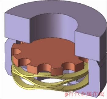
Figure 19 Plat valves for high frequency oscillation pumps
Table 6 Opening degree and flow parameters of three kinds of valves
6 Conclusions
In this paper, a reasonable meshing of the flow field model in the plate valve was carried out. The pressure distribution and flow velocity distribution of the internal flow field model under two-hole and three-hole spool structures were analyzed. The results show that the vortex is generated on the outlet side of the valve when the two-hole valve is opened to 0.4 mm, and the vortex increases with the increase of the opening. This causes instability in the flow field. When the opening degree reaches 1.2 mm, the obvious low-pressure zone appears on the outlet side of the spool, which easily generates cavitation phenomenon and also causes instability of the flow field. Therefore, the opening degree of the two-hole spool should not exceed 1.0 mm. The three-hole spool has a similar flow field change with the two-hole spool, but it does not create a low pressure zone, which shows that the flow field inside is more stable. When the valve port is opened, the pressure first decreases and then increases. Compared with the two-hole spool, the three-hole spool has a shorter time to enter the stationary phase, and the vortex is not obvious. The flow rate of the three-hole plate valve is slightly smaller than that of the two-hole plate valve, but its stability is much better than that of the two-hole spool. The three-hole spool has a greater stable opening degree and can be greater than 1.0 mm. The greater the opening degree, the greater the flow, which compensates for the problem that the flow is slightly smaller than that of the two-hole spool. However, considering its high speed, the opening degree should not be too large. Referring to the opening degree of the same size spool, the maximum opening degree should be 1.2 mm. Based on the above reasons, the plate valve with three-hole spool structure is selected to study. In order to further verify the pressure stability of the three-hole plate valve, the simulation calculation of the three-hole plate valve under different pressures is carried out. The results demonstrate the stability of the three-hole spool at a working pressure of 2 MPa or less. The flow characteristics of plate type high speed on-off valves and existing hydraulic valves are compared. The results show that the three-hole plate type high speed on-off valve designed in this paper keeps the internal flow field stable under the condition of 200 Hz frequency and large opening degree, and achieves the increase of flow rate.
References
[1] TU H C, RANNOW M B, WANG M, LI P Y. Design, modeling, and validation of a high-speed rotary pulse-width-modulation on/off hydraulic valve [J]. Journal of Dynamic Systems, Measurement, and Control, 2012, 134: 1-13.
[2] RANNOW M B, TU H C, WANG M, LI P Y. The advantages and feasibility of externally actuating a high- speed rotary on/off valve [C]// Proceedings of the 52nd National Conference on Fluid Power (NCFP 2011). Las Vegas, US: NCFP, 2011: 526-537.
[3] MAURO V, ALDO S. Hardware-in-the-loop (HIL) testing of ESP (Electronic Stability Program) commercial hydraulic units and implementation of new control strategies [J]. SAE Transactions, 2004, 113(6): 1177-1185. DOI: 10.4271/2004- 01-2770.
[4] MAURO V. A methodology to investigate the dynamic characteristics of ESP and EHB hydraulic units [C]// SAE 2006 World Congress. 2006: 13495-13509.
[5] MAURO V, ALDO S. Hardware-in-the-loop (HIL) testing of ESP (Electronic stability program) commercial hydraulic units and implementation of new control strategies [C]// 22nd Annual Brake Colloquium & Exhibition. 2004: 1-11.
[6] HU Jin-xiang, LI Jian-jun, ZHONG Ding-qing. High speed on-off valve and its development trend [J]. Development & Innovation of Machinery & Electrical Products, 2009, 22: 60-62. DOI: 10.3969/j.issn.1002-6673.2009.02.026. (in Chinese)
[7] TANG Bing, LIU Yu-hui, SI Guo-lei, YANG Guo-lai. Research on key technology of pilot type high flow high speed on-off valve [J]. Chinese Hydraulics & Pneumatics, 2018(10): 76-83. DOI: 10.11832/j.issn.1000-4858.2018.06. 015. (in Chinese)
[8] TIAN Xin-min. Electro-hydraulic valve timing mechanism without camshaft [J]. Foreign Internal Combustion Engine, 2000(1): 62-63. (in Chinese)
[9] LEATI E, SCHEIDL R, PLOECKINGER A. On the dynamic behavior of check valves for high frequency oscillation pumps [C]// ASME/Bath Symposium on Fluid Power and Motion Control, V001T01A01, 2013.
[10] CAO Bing-gang, GUO Mao-ying, SHI Wei-xiang, KAZUO N. Boundary element method analysis of flow field of cone valve [J]. Machine Tool & Hydraulics, 1991, 36: 2-10. (in Chinese)
[11] TANG Zhi-yong, CAO Bing-gang, SHI Wei-xiang. Discussion on steady-state wave dynamic compensation method of hydraulic control valve-casing movement method [J]. Machine Tool & Hydraulics, 1995(5): 91-95, 123. (in Chinese)
[12] DENG Chun-xiao, PAN Di-lin. Finite element analysis and optimization design of hydraulic cone valve [J]. General Machinery, 2004(10): 61-63, 72. DOI: 10.3969/j.issn.1671- 7139.2004.08.033. (in Chinese)
[13] BATDORFF M A, LUMKES J H. Fast-acting fluid control valve: US: 20070750180 [P]. 2010-05-18.
[14] FANG Zhi, LI Zhi-gang, LI Jun. Study on the influence of geometric parameters on the characteristics of hole seal leakage and blast heating [J]. Journal of Xi��an Jiaotong University, 2019, 53(1): 1-7. DOI: 10.7652/xjtuxb20190 1018. (in Chinese)
[15] SRIKANTH C, BHASKER C. Flow analysis in valve with moving grids through CFD techniques [J]. Advances in Engineering Software, 2009, 40(3): 193-201.
[16] MIGLIORINI P J, UNTAROIU A, WOOD H G. A numerical study on the influence of hole depth on the static and dynamic performance of hole-pattern seals [J]. ASME Journal of Tribology, 2015, 137(1): 259-263.
[17] CHILDS D W, ARTHUR S, MEHTA N J. The impact of hole depth on the rotor dynamic and leakage characteristics of hole-pattern-stator gas annular seals [C]// ASME Turbo Expo 2013: Turbine Technical Conference and Exposition. American Society of Mechanical Engineers Digital Collection.
[18] GUO Chang-sheng. Simulation of pressure regulating valve flow field and analysis of spool motion based on moving grid [D]. Chongqing: Chongqing University, 2013. DOI: 10.7666/d. D354206. (in Chinese)
[19] HE Qing-zhong, LIU Yu-cong, ZHAO Xian-dan, LIU Jia. Opening characteristics of tri-eccentric butterfly valve based on CFD dynamic mesh technique [J]. Journal of Drainage and Irrigation Machinery Engineering, 2018, 12(5): 1-4. DOI: 10.3969/j.issn.1674-8530.16.0282. (in Chinese)
[20] LI Peng. Application of unstructured dynamic mesh technique in flow field simulation of submunitions separation [D]. Nanjing: Nanjing University of Science and Technology, 2013. DOI: 10.7666/d.Y2277251. (in Chinese)
[21] YANG Yang, ZHANG Yi. Dynamic characteristics analysis of poppet valve and ball valve hydraulic valve based on AMESim [J]. Coal Mine Machinery, 2015, 36: 154-155. DOI: 10.13436/j.mkjx.201504061. (in Chinese)
[22] FENG Yi-jiang, JIANG Jun, CAI Zheng, ZHU Hai-xiang. Research on anti-pollution structure of hydraulic valve [J]. Construction Machinery, 2018, 49: 38-41, 96. DOI: 10.3969/j.issn.1000-1212.2018.05.008. (in Chinese)
[23] MAN Guo-jia. Simulation and experimental study on cavitation and noise of hydraulic cone valve [D]. Harbin: Harbin University of Science and Technology, 2018. (in Chinese)
[24] XU Jing-jin. ANSYS 13.0 Workbench numerical simulation technology [M]. Beijing: China Water & Power Press, 2012. (in Chinese)
[25] WANG Xiao-jing, SHEN Zhi-qi, MAN Guo-jia. Simulation and experiment of cavitation phenomenon two-phase flow of hydraulic cone valve [J]. Journal of Harbin Institute of Technology, 2019, 51(7): 144-153. DOI: 10.11918/j.issn. 0367-6234.201806016. (in Chinese)
[26] MOU Jie-gang, DAI Dong-shun, GU Yun-qing, LIU Jian, WU Deng-hao, MA Yi. Influences of impeller ring structure on performance and flow field of centrifugal pump [J]. Journal of Central South University (Science and Technology), 2017, 48(6): 1522-1529. DOI: 10.11817/j.issn. 1672-7207.2017.06.015. (in Chinese)
(Edited by ZHENG Yu-tong)
���ĵ���
��ʽ���ٿ��ط���о�ṹ���Ż�����������
ժҪ�����ٿ��ط��ڲ�������Ը��ӵ�����״̬���ڷ�о�������չ����в�����ѹ������Һ������������Ѩ�����е�����Ӱ��巧�ڲ������ȶ����Լ����ٿ��ط����������ԡ���Ը��ٿ��ط�����С�����������ȶ������⣬�����һ�����͵ķ�о�ṹ�������˲�ͬ���ڵĶ������װ����������ģ�ͣ���ѡ��ANSYS Workbench������ģ�ͽ�����������������FLUENT����������ѡ���k-������ģ�ͽ�����ֵģ���о����õ�������ͬѹ���Ͳ�ͬ���ڶ��µ�ѹ���ֲ����ٶȷֲ����õ����Ż�ģ�͵Ľṹ�Ͳ������Բ�ͬѹ���µ������������ȶ��Է���������о�������仯�����о���ƣ��������γɵ�ѹ��������о��2 MPa�����¾����ȶ������������˷�о���ٿ��չ����е�ѹ������Һ������������˸��ٿ��ط��������ȶ��Ժ����������Ա��˱�����Ƶİ�ʽ���ٿ��ط�������Һѹ����Ʒ���������ԡ����������������Ƶ����װ�ʽ���ٿ��ط���200 Hz�ͽϴڶ����ܹ������������ȶ�������ʵ����������������
�ؼ��ʣ����ٿ��ط����������棻����ѹ������
Foundation item: Project(51975164) supported by the National Natural Science Foundation of China; Project(201908230358) supported by the China Scholarship Council; Project supported by the Fundamental Research Foundation for Universities of Heilongjiang Province, China
Received date: 2019-08-06; Accepted date: 2020-02-13
Corresponding author: WANG Xiao-jing, PhD, Professor; Tel: +86-18903669159; E-mail: hitwangxiaojing@163.com; ORCID: 0000- 0001-6285-9193
Abstract: There is a relatively complex flow state inside the high speed on-off valve, which often produces low pressure area and oil reflux in the high-speed opening and closing process of the spool, causing cavitation and vortex and other phenomena. These phenomena will affect the stability of the internal flow field of the plate valve and the flow characteristics of the high speed on-off valve. Aiming at the problems of small flow rate and instability of internal flow field, a new spool structure was designed. The flow field models of two-hole and three-hole plate spools with different openings were established, and software ANSYS Workbench was chosen to mesh the model. The standard k-�� turbulence model was selected for numerical simulation using FLUENT software. The pressure distribution and velocity distribution under the same pressure and different opening degree were obtained. The structure and parameters of the optimization model were also obtained. The stability analysis of flow field under different pressure was carried out. The results demonstrate that the three-hole spool has a similar flow field change with the two-hole spool, but it does not create a low pressure zone, and the three-hole spool can work stably at 2 MPa or less. This method improves the appearance of low pressure area and oil backflow in the process of high speed opening and closing of spool. The stability of flow field and the flow rate of high speed switch valve are improved. Finally, the products designed in this paper are compared with existing hydraulic valve products. The results show that the three-hole plate type high speed on-off valve designed in this paper maintains the stability of the internal flow field under the condition of 200 Hz and large opening degree, and realizes the increase of flow rate.
