
J. Cent. South Univ. Technol. (2010) 17: 529-536
DOI: 10.1007/s11771-010-0518-0![]()
Numerical and experimental analysis of quenching process for
cam manufacturing
TANG Qian(��ٻ)1, PEI Lin-qing(������)1, XIAO Han-song(Ф����)2
1. State Key Laboratory of Mechanical Transmissions, Chongqing University, Chongqing 400044, China;
2. Department of Mechanical and Industrial Engineering, University of Toronto, Toronto, Ontario M5S 3G8, Canada
? Central South University Press and Springer-Verlag Berlin Heidelberg 2010
Abstract:
In order to obtain satisfactory mechanical properties for the cam used in high-power ship diesel engines, a new quenching technology was proposed by designing a two-stage quenching process with an alkaline bath as the quenching medium. To demonstrate the effectiveness of the proposed new quenching technology, both numerical analysis and experimental study were performed. The new quenching technology was analyzed using finite element method. The combined effects of the temperature, stress and microstructure fields were investigated considering nonlinear material properties. Finally, an experimental study was performed to verify the effectiveness of the proposed new quenching technology. The numerical results show that internal stress is affected by both thermal stress and transformation stress. In addition, the direction of the internal stress is changed several times due to thermal interaction and microstructure evolution during the quenching process. The experimental results show that the proposed new quenching technology significantly improves the mechanical properties and microstructures of the cam. The tensile strength, the impact resistance and the hardness value of the cam by the proposed new quenching technology are improved by 4.3%, 8.9% and 3.5% compared with those by the traditional quenching technology. Moreover, the residual stress and cam shape deformation are reduced by 40.0% and 48.9% respectively for the cam manufactured by the new quenching technology.
Key words:
1 Introduction
As an essential part of a high-power ship diesel engine, a cam must have a working surface with enough hardness, wear resistance, and toughness in order to have a guaranteed lifespan when working under severe conditions, including heavy load, high temperature, and fatigue. To meet the requirements for mechanical properties of the cam, a quenching process is widely used in the manufacturing of cams. However, traditional quenching processes adopted by domestic cam manufacturers cannot provide satisfactory mechanical properties for the cam. This is indicated by spot corrosion, cracks, and rapid erosion on the working surface of the cam within the designed work cycle. Moreover, traditional quenching processes, which generally consist of only one stage of quenching at a specified temperature, have difficulty in accurately analyzing the temperature and stress fields during the quenching process of the cam. In recent years, a technology has been proposed in this subject. Different from the traditional quenching process, the new quenching technology consists of two stages of quenching, with an alkaline bath as the quenching medium. It is believed that the proposed new quenching technology brings major advantages over the traditional quenching process, including better mechanical properties, better microstructures, and more accurate shape and dimensions.
The quenching process is a complicated process in which interaction occurs among cooling rate, temperature variation, phase transformation, and stress-strain state. For various microstructures during the quenching process, the thermophysical properties of materials (including thermal conductivity, heat transfer coefficient, and specific heat at a constant pressure) and mechanical properties (including elastic modulus, plastic modulus, Poisson ratio, and yield strength), change continuously with the temperature variation. Since the process involves high nonlinearity of the cam material [1], it is very difficult to accurately analyze the temperature and stress fields during the quenching process of the cam. In recent years, a number of numerical investigations have been performed to predict the changes of temperature and stress fields of the cam during the quenching process [2-8]. For example, YAO et al [3] studied the oil quenching process of GCr15 tube using finite element method after determining the heat transfer coefficient of oil. The temperature, microstructure and stress variations during quenching were analyzed. HOSSAIN et al [4] predicted the residual and thermal stresses that occur during water quenching of solid spherical balls. KANG and IM [6] established a 3D thermo-elastic-plastic model for plain-carbon steel along with phase transformation to improve the accuracy of numerical simulation. KAKHKI et al [9] simulated the continuous cooling and kinetics of phase transformation and predicted the final distribution of microstructures and hardness in low alloy steels using measured heat transfer coefficients of quenching media by an inverse method. ULYSSE and SCHULTZ [10] investigated the effect of various surface treatments on the thermo- mechanical response of cylindrical aluminum missiles during warm water quenching. In the review of the past studies on analyzing the quenching process, most of studies were solely focused on numerical simulation for one-stage liquid-quenching. Only a few studies [9-12] conducted experimental investigations to verify the accuracy of simulation results. Moreover, the geometry of the specimens analyzed in those previous studies was quite simple, such as cylinders or thin plates.
In this work, a new quenching technology was proposed by using a two-stage quenching process with an alkaline bath as the quenching medium. To demonstrate the effectiveness of the proposed quenching technology, both numerical and experimental studies were performed. The analytical models were established to investigate the coupling effects of the microstructure, temperature, and stress fields. The nonlinearity of the cam material was considered by combining the measured heat transfer coefficient and the empirical physical properties. The finite element method was then applied to analyzing the temperature and stress fields of the cam during the quenching process. To verify the effectiveness of the new quenching technology, an experimental study was performed.
2 Analytical model
2.1 Temperature field
Quenching is defined as a transient heat conduction problem with convective boundary conditions and internal heat source. The heat flux across a boundary layer on the surface is dependent on the surface temperature, temperature of the quenching medium, and the convective heat transfer coefficient of the quenching medium. Considering the influence of latent heat from phase transformation, the partial differential equation (PDE) of heat conduction is expressed as follows by using Fourier law:
![]()
(1)
The initial condition and boundary condition are given as
![]() (2)
(2)
![]() (3)
(3)
where �� is the density of the material; c is the specific heat capacity of the material; kx, ky, and kz are thermal conductivity coefficients along three directions of x, y, and z; t is the time instant; Q is the latent heat of phase transformation; n is the normal direction; h is the whole heat transfer coefficient; T, Ta, and T0 are the surface temperature, medium temperature, and initial temperature of the cam, respectively.
2.2 Microstructure field
Because of the high level of presence of nickel (Ni) and chromium (Cr) in the cam specimen, an appropriate hardenability is expected. Therefore, the specimen contains a large amount of martensite, a small amount of austenite, and very little carbide after the quenching process with the alkaline bath. Only martensite transformation is considered in the numerical analysis. The martensite volume fraction can be expressed as follows by using the dynamic equation of temperature- varying martensite transformation [13]:
![]() (4)
(4)
where TMs is the temperature when martensite starts transforming; T1 is the temperature of specimen; k is the rate of martensite transformation, which is selected as 0.011 in this work.
2.3 Stress and strain
The quenching process consists of both elastic deformation and plastic deformation. Due to the complexity, it is difficult to establish the constitutive relation of the material. Generally, the total strain increment is considered to be the sum of the following components: elastic strain increment, plastic strain increment, and strain increment caused by volume change, which is expressed as:
![]() (5)
(5)
where superscripts e, p, th and tr represent the elastic strain increment, plastic strain increment, thermal strain increment, and phase transformation strain increment, respectively.
The phase transformation increment is evaluated as [14]:
![]() (6)
(6)
![]() (7)
(7)
The thermal strain increment is calculated as [15]:
![]() (8)
(8)
where ![]() is the volume expansion coefficient for martensite transformation at temperature T;
is the volume expansion coefficient for martensite transformation at temperature T; ![]() is volume expansion coefficient for martensite transformation at 0 ��;
is volume expansion coefficient for martensite transformation at 0 ��; ![]() and
and ![]() are the thermal expansion coefficients of martensite and austenite, respectively; V is the volume of martensite transformation; m is the parameter determined from experiments; and
are the thermal expansion coefficients of martensite and austenite, respectively; V is the volume of martensite transformation; m is the parameter determined from experiments; and ![]() is the coefficient of thermal expansion.
is the coefficient of thermal expansion.
When the material stress appears on the yield surface, the elasto-plastic behavior must be taken into account if the load further increases. The elasto-plastic stress-strain relationship is derived as follows by assuming the strain is small [16]:
![]() (9)
(9)
where ![]() and
and ![]() and
and ![]() are the elastic and plastic matrices, respectively;
are the elastic and plastic matrices, respectively; ![]() is the stress increment; subscript kl indicates elasto-plastic behavior.
is the stress increment; subscript kl indicates elasto-plastic behavior.
The explicit expressions of the isotropic material can be given as:
![]() (10)
(10)
![]() (11)
(11)
![]()

(12)
where si is the component of deviatoric stress tensor; ��i is the component of shear stress; E is the elastic modulus; ��s is the yield limit; and Ep is the hardening coefficient; De and Dp are the elastic matrix and the plastic matrix of explicit expressions, respectively; �� is the Poisson ratio; and G is the shear modulus.
3 Finite element analysis
The finite element method is applied to analyzing the two-stage quenching process for the proposed new quenching technology. Fig.1 illustrates the procedure of the finite element analysis (FEA) for the prediction of the temperature, microstructure and stress fields through considering thermal interaction, microstructure evolution and elastic-plastic deformation during the quenching process. The physical model of the cam specimen and mesh system in the FEA is shown in Fig.2. The computerized model of the cam is meshed using hexahedral element, and the whole model consists of 36 570 elements. It is assumed that all the elements are isotropic and have a linear displacement field.
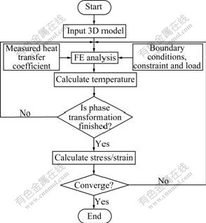
Fig.1 Flowchart for analyzing quenching process of cam
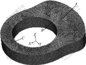
Fig.2 Finite element model of cam
The material of the cam is 12CrNi3 steel. The major geometry of the cam model is described as follows. In x-axis direction shown in Fig.2, the internal diameter is 269 mm, the outer diameter is 405 mm, and the thickness is 107 mm. Without loss of generality, the following assumptions are made in solving the problem.
(1) During the thermal analysis, the initial temperatures of the inner parts are the same and heat transfer coefficient of the outer surface of the cam is uniform.
(2) The temperature of the alkaline is kept at the initial temperature throughout the quenching process.
(3) During the thermal-stress analysis, the initial stress of the material prior to quenching is set as zero, and the nodal displacement of the end face is also set as zero.
The surface heat transfer coefficient plays an important role in accurately calculating the stress and temperature fields. Therefore, an experiment was conducted to measure the surface heat transfer coefficient of the alkaline bath. The experiment was designed as follows: a 1Cr18Ni9Ti stainless steel probe was uniformly heated to 1 000 ��, and then cooled down using the alkaline bath. The data measured by the thermocouple were stored. After the experiment, the surface heat transfer coefficient of the alkaline bath was obtained by using the inverse heat conduction method to process the measured data [17]. The obtained curve for the surface heat transfer coefficient is shown in Fig.3. It can be observed in the figure that the coefficient varies with the surface temperature of the specimen, and the heat transfer capacity reaches the highest level at around 650 ��. The curve of the measured surface heat transfer coefficient, together with various thermophysical parameters obtained from Ref.[18], is incorporated into the analysis procedure of the quenching process to improve the accuracy of the numerical results.
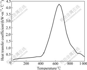
Fig.3 Surface heat transfer coefficient of alkaline bath
4 Simulation results and discussion
4.1 Temperature field
Fig.4 illustrates the temperature variations of nodes A, B, and C on the surface of the cam (shown in Fig.2) for the proposed new quenching technology.
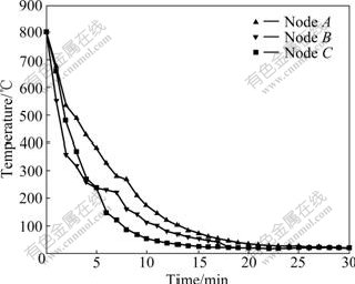
Fig.4 Cooling history of selected nodes on cam surface
Due to the interaction between the radiation of the cam and the convection heat transfer of the medium, the temperatures of all the three nodes vary with a great gradient. At the beginning of the cooling process, nodes A, B, and C are cooled quickly at a similar speed because of direct contact with the alkaline liquid. As the quenching process continues, the heat sources nodes obtained from the core are different due to the change of microstructure field and the heterogeneity of the structure. Node A obtains the maximum and cools the slowest; node C obtains the minimum and cools the fastest.
It is clearly shown that the temperature differences between the three nodes decrease gradually during the quenching process.
It can be observed that there is a protrusion for all the three curves shown in the figure. For example, for the curve of node C, the protrusion can be seen at around 250 ��. The reason is that when the temperature is around 250 ��, martensite transformation will occur. Therefore, the latent heat generated by microstructures causes a temperature increase on the surface and hence the curve shows a protrusion point. This phenomenon agrees with the known practical process.
Fig.5 shows the calculated temperature history at a node on the cam surface. For comparison, an experiment was performed to measure the temperature of the corresponding node on the surface of the cam specimen by using infrared thermography throughout the quenching process. The measured temperature history is also included in the figure. Compared with the measured temperature, the simulation results are quite consistent with the measured temperatures with very small margins. In addition, Fig.6 illustrates the calculated temperature field distribution contour at the time instant of 200 s after the quenching starts.
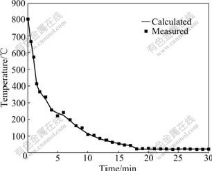
Fig.5 Comparison of temperature variations of node on cam surface
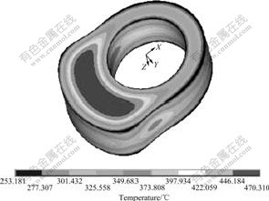
Fig.6 Temperature distribution contour of quenching at 200 s
4.2 Stress field
Fig.7 shows the axial stress of a center node and a surface node of the cam. The internal stress is the outcome of the interaction between the thermal stress and phase transformation stress. At the beginning of the cooling, due to the quick surface cooling, the surface shrinkage is restricted by the core structure. Therefore, as shown in the figure, the surface node exhibits tensile stress, while the center node exhibits compressive stress, and the thermal stress quickly increases. As the quenching process continues, the temperature gradient decreases, as shown in Fig.4 or Fig.5. As a result, the tensile stress at the surface node reduces accordingly. At the time instant around 5 min, the surface temperature reduces to point TMs, where the martensite transformation occurs and hence the microstructure volume expands. While the center node is still above point TMs, and the volume does not change dramatically. Therefore, the tensile stress on the surface node quickly changes into the compressive stress. While in the subsequent cooling, the thermal stress propagates to the inner layer and the volume of the center continues to shrink. Due to the restraint from the surface structure, the stress of the center node changes from the compressive stress to the
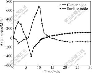
Fig.7 Axial stress of center node and surface node
tensile stress and then reaches up to 700 MPa, as shown in Fig.7. At the end of quenching process, the direction of stress reverses again for the center node due to martensite transformation. Therefore, the surface node exhibits tensile residual stress, while the center node exhibits compressive residual stress.
5 Experimental verification
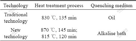
Since the temperature and stress fields of the cam are obtained through the FEA of the cam quenching process, the accuracy of the numerical results must be checked with the experimental results. The experiment was designed as follows: two groups of cam specimens (d110 mm��130 mm) where their total numbers is 6 (n=6), were manufactured using the traditional quenching technology and the proposed new quenching technology listed in Table 1, respectively. For the tensile test, the samples (d16 mm��110 mm) were chosen from the 1/3 R (R is the radius of specimen) to the cam specimens surface according to the National Standard GB 6397��86, where its diameter is d10 mm in standard distance. A universal tensile testing machine (CCS��92) was used, with the tensile speed of 3 mm/min and load cell of 50 kN. In addition, for the impact test, the depth was 2 mm for U-type gap of samples (10 mm��10 mm��55 mm) selected according to the National Standard GB/T 229��1994, an impact tester (PSW-3000) was used, and a Rockwell hardness meter was used for hardness test. Finally, nitric acid alcohol solution of 4% (mass fraction) was applied to metallographic specimen for 15-30 s, and then a XJZ-64 optical microscope was used for structure inspection and pictures were taken.
Table 1 Quenching technologies of different methods
Figs.8-12 show the mechanical properties of the tested cam specimens. From those figures, it can be observed that the mechanical properties obtained from the proposed new quenching technology are better than those of the traditional one. A quantitative comparison is
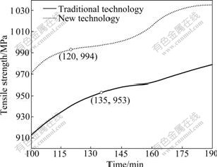
Fig.8 Comparison of tensile strength between new technology and traditional technology
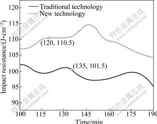
Fig.9 Comparison of impact resistance between new technology and traditional technology
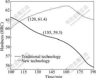
Fig.10 Comparison of hardness between new technology and traditional technology
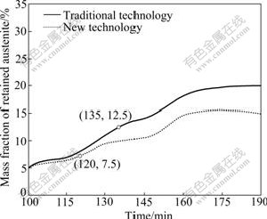
Fig.11 Comparison of mass fraction of retained austenite between new technology and traditional technology
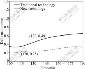
Fig.12 Comparison of deformation between new technology and traditional technology
also made and listed in Table 2 to clearly present the results. Specifically for the proposed quenching technology, tensile strength, impact resistance and hardness value are improved by 4.3%, 8.9% and 3.5%, as shown in Figs.8, 9, and 10, respectively.
Fig.11 illustrates that less austenites are retained with the proposed quenching technology. As a result, both the irregular deformation tendency and deformation quantity during the cam operation are significantly reduced. The deformation is reduced by 48.9% compared to that by the traditional technology, as shown in Fig.12.
Fig.13 shows the microstructures of the cam center. Compared to the cam manufactured with the tradition quenching technology, the cam manufactured with the new technology demonstrates better microstructures. Specifically, the structure of the quench-hardened layer reaches martensite level 3, residual austenite level 2 and carbide level 2, which indicates satisfactory microstructures. The reason for that the new quenching technology results in better microstructures is explained
Table 2 Comparison of mechanical properties and deformation between new technology and traditional technology
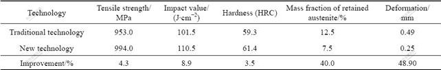
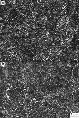
Fig.13 Final center microstructures of cam obtained from traditional technology (a) and new technology (b)
as follows. During the quenching process, a great difference between the internal and external temperatures probably generates a high level of thermal stress and heat deformation. This requires a quick cooling above the critical temperature (martensite transformation temperature), and then a slow cooling below the critical temperature. As a result, more martensites are formed. Compared with the traditional oil quenching, the new two-stage quenching process with the alkaline bath is able to achieve such a cooling process. Therefore, it can remarkably reduce the quenching temperature difference and generate reasonable microstructures.
In summary, the experimental study shows that compared to the cam manufactured with the traditional technology, the mechanical properties including tensile strength, impact resistance, and hardness of the cam manufactured with the proposed new quenching technology are improved. Moreover, the shape deformation is significantly decreased, and the microstructures are more uniform and regular. In conclusion, the experimental results demonstrate that the proposed new quenching technology is superior to the traditional quenching technology.
6 Conclusions
(1) The simulated temperature field of the cam using the measured heat transfer coefficient as a boundary condition shows a good agreement with the measured temperature.
(2) The directions of the internal stress change several times due to thermal interaction and microstructure evolution over the quenching process.
(3) Using the alkaline bath as the quenching medium has better cooling characteristics than using the traditional oil. The cam cools quickly above the critical temperature (martensite transformation temperature) and slowly down afterward. The shape transformation is reduced remarkably and reasonable microstructures are generated.
(4) Mechanical properties and microstructures are improved significantly by adopting the two-stage quenching technology.
References
[1] LI Hui-ping, ZHAO Guo-qun, HE Lian-fang. Finite element method based simulation of stress-strain field in the quenching process [J]. Materials Science and Engineering A, 2008, 478(1/2): 276-290.
[2] TOPARLI M, SAHIN S, OZKAYA E, SASAKI S. Residual thermal stress analysis in cylindrical steel bars using finite element method and artificial neural networks [J]. Computers and Structures, 2002, 80(23): 1763-1770.
[3] YAO Xin, GU Jian-feng, HU Ming-juan, ZHANG Wei-min. Numerical simulation of the quenching process of GCr15 steel tube [J]. Transactions of Materials Heat Treatment, 2003, 24(1): 78-81. (in Chinese)
[4] HOSSAIN S, DAYMOND M R, TRUMAN C E, SMITH D J. Prediction and measurement of residual stresses in quenched stainless-steel spheres [J]. Materials Science and Engineering A, 2004, 373(1/2): 334-349.
[5] G?R C H, TEKKAYA A E. Numerical investigation of non-homogeneous plastic deformation in quenching process [J]. Material Science and Engineering A, 2001, 312/319: 164-169.
[6] KANG S H, IM Y T. Three-dimensional thermo-elastic-plastic finite element modeling of quenching process of plain-carbon steel in couple with phase transformation [J]. International Journal of Mechanical Sciences, 2007, 49(4): 423-439.
[7] SEN S, AKSAKAL B, OZEL A. Transient and residual thermal stress in quenched cylindrical bodies [J]. International Journal of Mechanical Sciences, 2000, 42(10): 2013-2029.
[8] CORET M, CALLOCH S, COMBESCURE A. Experimental study of the phase transformation plasticity of 16MND5 low carbon steel under multiaxial loading [J]. International Journal of Plasticity, 2002, 18(12): 1707-1727.
[9] KAKHKI M E, KERMANPUR A, GOLOZAR M A. Numerical simulation of continuous cooling of a low alloy steel to predict microstructure and hardness [J]. Modelling and Simulation in Materials Science and Engineering, 2009, 17(4): 1-21.
[10] ULYSSE P, SCHULTZ R W. The effect of coatings on the thermo-mechanical response of cylindrical specimens during quenching [J]. Journal of Materials Processing Technology, 2008, 204(1/3): 39-47.
[11] SONG D L, GU J F, PAN J S, HU M J. Numerical simulation of quenching of large sized blocks of 718 steel used for plastic dies [J]. Materials Science and Technology, 2004, 20(12): 1567-1572.
[12] DOLAN G P, FLYNN R J, TANNER D A, ROBINSON J S. Quench factor analysis of aluminium alloys using the Jominy end quench technique [J]. Materials Science and Technology, 2005, 21(6): 687-692.
[13] LI Hui-ping, ZHAO Guo-qun, HUANG Chuan-zhen, NIU Shan-ting. Technological parameters evaluation of gas quenching based on the finite element method [J]. Computational Material Science, 2007, 40(2): 282-291.
[14] SONG Guang-sheng, LIU Xiang-hua, WANG Guo-dong, XU Xiang-qiu, LI Guo-chen. Numerical simulation of microstructure and stress in carburizing and quenching process of 22CrMo steel [J]. Journal of Iron and Steel Research, 2006, 18(10): 36-40. (in Chinese)
[15] WANG De-guang, WU Yu-cheng, JIAO Ming-hua, YU Jian-wei, XIE Ting. Finite element simulation of influence of different compacting processes on powder metallurgic products properties [J]. Chinese Journal of Mechanical Engineering, 2008, 44(1): 205-211. (in Chinese)
[16] WANG Xu-cheng. Finite element method [M]. Beijing: Tsinghua University Press, 2003: 1-776. (in Chinese)
[17] YUAN Jian, ZHANG Wei-min, LIU Zhan-cang, CHEN Nai-lu, WANG Ming-hua, XU Jun. The measurement and calculation of heat transfer coefficient under cooling conditions [J]. Transactions of Materials and Heat Treatment, 2005, 26(4): 115-119. (in Chinese)
[18] TAN Zhen, GUO Guang-wen. Thermophysical properties of engineering alloys [M]. Beijing: Metallurgical Industry Press, 1994: 1-228. (in Chinese)
Foundation item: Project(50875268) supported by the National Natural Science Foundation of China; Project(CSTC2008AB3057) supported by Foundation of Chongqing Science and Technology Commission, China; Project(108107) supported by the Key Project of Ministry of Education of China; Project(50925518) supported by the National Science Fund for Distinguished Young Scholars
Received date: 2009-08-26; Accepted date: 2009-12-29
Corresponding author: TANG Qian, PhD, Professor; Tel: +86-23-65111276; E-mail: tqcqu@cqu.edu.cn
(Edited by CHEN Wei-ping)
Abstract: In order to obtain satisfactory mechanical properties for the cam used in high-power ship diesel engines, a new quenching technology was proposed by designing a two-stage quenching process with an alkaline bath as the quenching medium. To demonstrate the effectiveness of the proposed new quenching technology, both numerical analysis and experimental study were performed. The new quenching technology was analyzed using finite element method. The combined effects of the temperature, stress and microstructure fields were investigated considering nonlinear material properties. Finally, an experimental study was performed to verify the effectiveness of the proposed new quenching technology. The numerical results show that internal stress is affected by both thermal stress and transformation stress. In addition, the direction of the internal stress is changed several times due to thermal interaction and microstructure evolution during the quenching process. The experimental results show that the proposed new quenching technology significantly improves the mechanical properties and microstructures of the cam. The tensile strength, the impact resistance and the hardness value of the cam by the proposed new quenching technology are improved by 4.3%, 8.9% and 3.5% compared with those by the traditional quenching technology. Moreover, the residual stress and cam shape deformation are reduced by 40.0% and 48.9% respectively for the cam manufactured by the new quenching technology.
