

J. Cent. South Univ. (2020) 27: 242-255
DOI: https://doi.org/10.1007/s11771-020-4292-3

Finite element analysis of road structure containing top-down crack within asphalt concrete layer
Pirmohammad Sadjad, Majd-shokorlou Yousef
Department of Mechanical Engineering, University of Mohaghegh Ardabili, Ardabil 179, Iran
 Central South University Press and Springer-Verlag GmbH Germany, part of Springer Nature 2020
Abstract:
In this paper, a four-layered road structure containing a top-down crack is investigated by performing finite element analyses in ABAQUS. In this study, in addition to the vertical load of a vehicle wheel, the horizontal load as well as its position with respect to the crack is also considered in the analyses, and the crack tip parameters including stress intensity factors (SIFs) and T-stress are then calculated. Moreover, influence of elastic modulus and thickness of the pavement layers on the crack tip parameters is studied. Results show that the horizontal and vertical loads along with their position with respect to the crack, elastic modulus and thickness of the road layers influence the crack tip parameters (KI, KII and T-stress) significantly. It was also found that for the cases that the vehicle wheel is positioned near the crack plane, only the shear deformation mode is observed at the crack tip; while, for the vehicle wheel positions far from the crack, only the opening mode is observed, and between these positions, both the opening and shear deformation modes (i.e., mixed mode I/II) are observed at the crack tip.
Key words:
asphalt concrete; top-down crack; stress intensity factors; T-stress; horizontal load; vertical load��
Cite this article as:
Pirmohammad Sadjad, Majd-shokorlou Yousef. Finite element analysis of road structure containing top-down crack within asphalt concrete layer [J]. Journal of Central South University, 2020, 27(1): 242-255.
DOI:https://dx.doi.org/https://doi.org/10.1007/s11771-020-4292-31 Introduction
Many distresses such as rutting, corrugating, shoving and cracking, influence asphalt pavements performance. The interactions between these distresses make design of asphalt pavements very complex. Among these distresses, cracking is a major threat for the performance of asphalt pavements. In recent years, many efforts have been made to minimize the cracking in asphalt overlay. It is well known that as a crack takes place within the asphalt concrete, the infiltration of water can lead to rapid degeneration of the road foundation. Therefore, there is a great need to comprehend the cracking mechanism for diminishing road degenerations. In terms of the propagation mechanism, cracks can be classified into fatigue cracks, reflective cracks (bottom-up) and top-down cracks. Many investigations have been performed on the fatigue cracking (see e.g.[1, 2]) and the reflective cracking (see e.g., [3-5]). These cracks are considered conversely, the top-down crack initiates from the road surface and then propagates downward. There are many causes responsible for top-down cracking such as traffic loads, environmental factor (for example pavement aging), thermal stresses due to extreme cooling rates [6, 7]. In particular, when a crack exists on the pavement surface, vehicle traffic can contribute the crack to propagate through the asphalt concrete thickness.
Most of the performed previous researches on the asphalt concretes are based on the experimental investigations. For example, some researchers [8-27] have performed fracture tests on the different laboratory specimens such as single edge notched beam (SENB), disc shaped compact tension (DC-T), semi-circular bend (SCB) to obtain fracture properties of the asphaltic materials. These experimental works are limited to these simple tests. On the other hand, conducting full-scale tests on the cracked asphaltic materials is far complicated, time consuming and difficult as well as requires huge costs. Thus, numerical techniques can be superseded instead which are more effective and powerful. Numerical investigations of cracked parts based on the fracture mechanics theory have been well established and employed by many researchers to study the crack growth behavior of different materials. For example, AYATOLLAHI et al [28- 31] have employed finite element (FE) method to probe crack growth in different materials. Several numerical researches have been also performed on the asphalt pavements; for example, ZHOU et al [32] performed two-dimensional FE analyses to compute SIFs at the tip of reflective crack within the road structure. HYUNWOOK et al [33] investigated reflective cracking in the airfield pavement using two-dimensional FE analyses, and obtained SIFs to consider if crack growth occurs by heavy airplane passages. More recently, AMERI et al [34] and AYATOLLAHI et al [35] have only studied the effect of the vertical traffic load position on the SIFs at the crack tip.
The literature review reveals that very limited investigations have been carried out on the top-down cracking in asphalt pavements. Particularly, the effects of horizontal loads (induced from the vehicle acceleration and vehicle brake) and its position on the crack parameters have not been investigated so far, which are studied in this paper. Furthermore, the effects of other parameters including elastic modulus and thickness of the pavement layers are also investigated in this paper. It is pointed out that a four-layered pavement structure, containing an edge surface crack, is utilized in the finite element analyses which are performed by ABAQUS.
2 Finite element modeling of cracked asphalt concrete
A four-layered road structure consisting of hot mix asphalt (HMA) as a top course, base, sub-base, and sub-grade course was used for determining stress intensity factors and T-stress at the crack tip. A surface crack of length c=7 cm was assumed within the top HMA course, and in the middle of the road (see Figure 1). It is noticed that the crack length influences the stress intensity factor significantly. The effect of this parameter is not considered in this research because of two reasons: i) other researchers like MIAO et al [36] have investigated the effect of crack length, ii) the main focus of this paper is on the effect of horizontal load. However, based on an investigation performed by MIAO et al [36], as the crack length increases, the stress intensity factor initially increases, and for crack lengths higher than 6 cm, it remains nearly constant. Therefore, the value of crack length was taken as 7 cm in this task to obtain the maximum value of stress intensity factor at the crack tip.
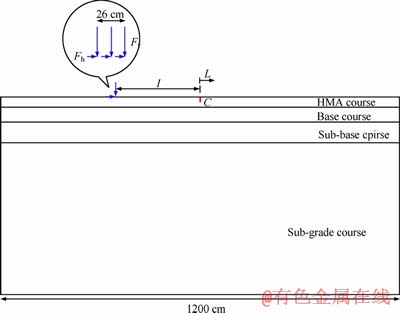
Figure 1 Cracked road sructure under traffic loads
Road length and vertical load inserted by a vehicle wheel were taken 1200 cm and 40 kN, respectively. In addition to the vertical load induced from the vehicle weight (Fv), the road was loaded horizontally (Fh) as well. Horizontal loads result from the vehicle acceleration or brake. Position of the loads (vehicle wheel) is described by parameter L. When the vehicle wheel is located in the left-hand side of the crack, sign of L is negative; while, it is positive when the vehicle wheel is located in the right-hand side of the crack. L=0 corresponds to the case that the wheel is positioned exactly on the crack.
Pavement layers including asphalt concrete, base layer, sub-base layer, and sub-grade layer are often assumed as homogen and isotrope. Moreover, these layers behave in linear elastic [37]. These assumptions work very well in the analyses as indicated by many researchers (see e.g. [38, 39]). It is also worth noting that the traffic loading is often very fast and occurs within a very short period. Thus, the HMA mixture can be assumed like a quasi-elastic material represented by the elastic modulus and Poisson ratio [32]. The mechanical properties of the conventionally used road structure in Iran pavement systems together with the reference thickness of the layers have been presented in Table 1. In this research study, cracked pavements were modeled using 8-node elements, and stress intensity factors (KI and KII) were extracted directly from ABAQUS using J-integral technique. Advantage of this technique is that the calculated value of J is path independent [40]. Therefore, this value was calculated for several contours around the crack tip, and the converged value of J was then selected as a valid value for obtaining the crack tip parameters. Figures 2(a) and (b) show sample mesh pattern employed in the finite element analyses. Singular elements with nodes at quarter-point positions, which are highly recommended for crack modeling, were used for the first ring of the elements around the crack tip. In the circular partitioned region surrounding the crack tip where the contour integrals are calculated, the mesh was biased toward the crack tip.
Table 1 Mechanical properties and thickness of road layers
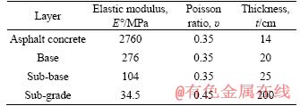
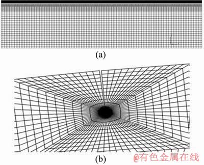
Figure 2 A typical mesh pattern used for road structure (a) and zoomed view of mesh pattern around crack tip in loaded road (b)
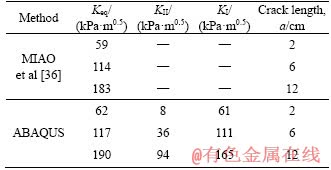
Before discussing on the fracture results of the road structure studied in this research, it is required to validate the finite element model used in this study. For this purpose, the research conducted by MIAO et al [36] was used. Figure 3 displays the cracked road structure investigated by them together with loading conditions and mechanical properties of the road layers. They calculated equivalent stress intensity factor (defined as Keq=(KI+KII)1/2) at the crack tip using boundary element method for deferent crack lengths (see Table 2). It is noticed that KI and KII are the mode I and mode II stress intensity factors. The cracked road structure was then modeled in finite element code (i.e., ABAQUS) to obtain the equivalent stress intensity factor at the crack tip. The results of ABAQUS are also presented in Table 2 to compare the results with those of MIAO et al [36]. The results presented in Table 2 indicate that the finite element analyses can correctly predict the fracture parameters of a cracked road structure. Hence, it can be concluded that the numerical model generated in ABAQUS can simulate fracture behavior of cracked road structures with sufficient accuracy.
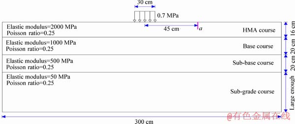
Figure 3 Cracked road structure investigated by MIAO et al [36] together with loading conditions and mechanical properties of road layers
Table 2 Comparison of results of equivalent stress intensity factor (i.e., Keq) obtained by ABAQUS with those of MIAO et al [36] for different crack lengths
3 Parametric study of cracked road structure
In this section, influence of the parameters including traffic loads and their positions, elastic modulus of the road layers, and thickness of the layers is examined and the obtained results are then discussed.
3.1 Horizontal and vertical loads
At the first step of this research, effect of the vertical load position was studied. As was mentioned earlier, a vertical load with the value of Fv=40 kN was applied on the road surface, and its position (L) with respect to the crack was then varied. Results for KI have been given in Figure 4(a). As is seen in this figure, KI has a negligible value where the vehicle wheel is far from the crack. By moving the wheel towards the crack, its value first increases and then, before standing on the crack (i.e., L=0), reduces to zero. Therefore, for near distances of the wheel from the crack, crack faces are completely closed (KI=0). These results can be explained by stress distribution inside the asphalt concrete layer loaded by the vehicle wheel. As is seen in Figure 5, stress at the region under the vehicle wheel is compressive; as a result, at this region (i.e., where the wheel is near the crack), the crack is closed because of the compressive stresses around the crack (KI=0). At far distances, status of the stresses is tensile which causes the crack to open (KI>0). It is also noted that because of the symmetry, KI has the identical value for equal positions of the wheel at before and after the crack (see Figure 4(a)) varied. Results for KI have been given in Figure 4(a). As is seen in this figure, KI has a negligible value where the vehicle wheel is far from the crack. By moving the wheel towards the crack, its value first increases and then, before standing on the crack (i.e. L=0), reduces to zero. Therefore, for near distances of the wheel from the crack, crack faces are completely closed (KI=0). These results can be explained by stress distribution inside the asphalt concrete layer loaded by the vehicle wheel. As is seen in Figure 5, stress at the region under the vehicle wheel is compressive; as a result, at this region (i.e. where the wheel is near the crack), the crack is closed because of the compressive stresses around the crack (KI=0). At far distances, status of the stresses is tensile which causes the crack to open (KI>0). It is also noted that because of the symmetry, KI has the identical value for equal positions of the wheel at before and after the crack (see Figure 4(a)).
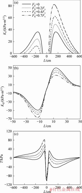
Figure 4 Variations of parameters KI (a), KII (b) and T-stress (c) versus vehicle wheel position with respect to crack (L) for different horizontal loads
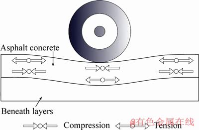
Figure 5 Stress distribution within asphalt concrete layer loaded by vehicle wheel
By moving vehicle on the road, in addition to KI, shear deformation mode (KII) was also observed at the crack tip. The results for KII have been given in Figure 4(b). As is clear from this figure, shear deformations take place only where the vehicle wheel is very near the crack. While, in this area, no opening deformation (KI=0) is seen at the crack tip. As a result, areas surrounding the crack can be classified into three zones. The first zone corresponds to the region farther from the crack that only pure mode I deformation is observed at the crack tip. The second zone corresponds to the very near distances from the crack which only pure mode II deformation is observed at the crack tip; and the third zone corresponds to the area between these two mentioned zones which mixed mode I/II deformation takes place. By approaching the vehicle wheel towards the crack, KII (with negative sign) first increases, and then reduces to zero where the wheel is located exactly on the crack. This can validate our FE results; because, when the wheel is situated on the crack, no shear deformation is expected to occur at the crack tip. As the wheel moves far away from the crack, KII (while its sign switches to positive) again increases, and then decreases. This sign change signifies that direction of the shear deformation has been changed. Consequently, the passage of vehicles on the cracked road may result in the fatigue crack growth. According to Figures 4(a) and (b), it is pointed out that the maximum (or critical) values of KI and KII occur at the L=143 cm and L=13 cm, respectively for all the horizontal loads.
Most of the researchers simplify their analyses, and do not consider influence of horizontal loads [41, 42]. Hence, in the next step, effect of the horizontal loads was studied. Depending on the severity of brake or acceleration, horizontal load Fh on the road surface has been reported ranging from 0 to 70% of the vertical load [43]. In this research, horizontal load Fh was varied with the magnitudes of 0, 0.2Fv, 0.4Fv and 0.7Fv; while, the vertical load was Fv=40 kN. By moving the vehicle wheel on the road, KI and KII at the crack tip alter as plotted in Figure 4. According to Figure 4(a), trend of KI variations for the cases that both vertical and horizontal loads are applied is similar to the one that only the vertical load is applied on the road. In other words, by moving the wheel towards the crack, KI first increases and then reduces to zero. As wheel approaches to the crack, horizontal load induced from the vehicle braking causes the crack faces to close. Therefore, KI for the case that both horizontal load and vertical load are applied on the road has lower value than that of the case that only vertical load is applied. While, when the wheel is situated on the right-hand side of the crack, the reverse results are observed, i.e., by increasing horizontal load, KI increases significantly. Presence of horizontal load with the values of 0.2Fv, 0.4Fv and 0.7Fv increases peak value of KI by 34%, 72%, and 125%, respectively. On the other hand, the horizontal load causes the crack faces to open at lower value of L, and to close at higher value of L (see Figure 4(a)). Therefore, it can be concluded that for the higher values of horizontal load, opening of the crack faces takes place at wider range of L. Trend of KII variations for the cases that both horizontal and vertical loads are applied is similar to the case that only vertical load is applied (which was explained above). Presence of the horizontal loads for L<0 causes KII to increase; while for L>0, KII decreases. The horizontal load with the values of 0.2Fv, 0.4Fv and 0.7Fv increases peak value of KII by 10%, 20%, and 35%, respectively. From the above results, it can be concluded that horizontal load more influences KI than KII. Moreover, for L<0, horizontal load decreases KI and increases KII, while the reverse manner is seen for L>0.
In addition to the singular terms (KI and KII), the non-singular stress term known as T-stress was also obtained directly from the ABAQUS. Importance of this term (T-stress) and how it influences stress distribution around the crack tip can be found in Refs. [44-47]. KI and KII state the stress singularity around the crack tip that control onset of the crack growth. Besides, T-stress and its sign also affect significantly the onset of mixed-mode fracture in the cracked parts. Negative value of T-stress increases the load bearing capacity of the cracked body under mixed-mode I/II loading, conversely the load bearing capacity decreases when positive T-stress exists at the crack tip.Figure 4(c) shows the results of T-stress for different wheel positions (L) and different horizontal loads. Similar to the results for KI and KII, when the wheel location is farther from the crack, magnitude of T-stress is zero. As the wheel moves toward the crack, T-stress first increases and then decreases dramatically. Another observation based on Figure 4(c) is that with the increase of horizontal load level, when the case is L<0, T-stress increases remarkably, and when L>0, T-stress behaves in an opposite manner. From above explanations, it can be stated that T-stress at the crack tip can accelerate the crack growth in the asphalt pavements.
As is implied from above, horizontal load induced from the vehicle acceleration or brake increases KI, KII and T-stress significantly. Therefore, at the intersections and where vehicles brake or accelerate, cracked asphalt concrete is subjected to critical loading condition, and consequently crack growth is more probable. As a result, an asphalt overlay with higher resistance against the crack growth must be used in these areas. Many researchers have attempted to increase asphalt concrete resistance against the crack propagation in the past years. For example, they [48-52] employed several binder modifiers, such as styrene�Cbutadiene�Cstyrene (SBS), ethylene-vinyl acetate (EVA), polyethylene, ethylene�Cglycidyl acrylate, ethylene-butyl acrylate, in HMA preparation; and their results showed that capability of the HMA mixtures against the crack growth increases.
Researchers often reported mode I fracture behavior of asphalt concretes in the past decades. They have used several test specimens to evaluate fracture property of asphalt concretes under mode I loading [53-55]. While, very few investigations concerning mixed mode I/II or pure mode II fracture have been reported in the literature [11, 15]). As our results showed, there are some cases that asphalt concrete is more vulnerable to mode II loading than to mode I loading. Hence, more investigations are required on the mixed mode I/II and mode II loading to better understand the crack growth mechanism under these loading conditions.
3.2 Elastic modulus
Another important parameter affecting the SIFs and T-stress at the crack tip is elastic modulus of the pavement layers. In this research, elastic modulus effect of all road layers shown in Figure 1 were examined at three levels of E��, 5E�� and 10E��. E�� corresponds to the reference elastic modulus of layers presented in Table 1. This range of elastic modulus (E) arises from a fact that temperature or aging influences elastic modulus of asphalt concrete significantly. For example, according to an investigation done by TIMM et al [56], elastic modulus of asphalt concrete increases over 10 times as the temperature drops from 25 ��C to -10 ��C. For other layers, aside from the temperature, elastic modulus may be changed by using other materials such as cement concrete as well. It is noted that for all investigations done herein, elasticity of the studied layer varied as above and elasticity of the other layers were kept fixed at values presented in Table 1 (E��). Besides, investigations on the elastic modulus of the road layers were developed for horizontal loads (Fh) at three levels of 0, 0.4Fv and 0.7Fv along with the vertical load.
3.2.1 Elastic modulus of asphalt concrete
Figure 6(a) shows the variations of KI against L for different elastic modulus (E) of the asphalt concrete. It is clear from this figure that for the case of Fh=0, with the increase of E, mode I stress intensity factor (KI) increases; moreover, KI begins to increase at lower value of L. The peak value of KI for the cases 5E�� and 10E�� with respect to that for the case of E�� is 3 and 5, respectively. Hence, KI is extremely dependent on the elastic modulus of the asphalt concrete; therefore, the temperature drop can be crucial for the crack propagation in the asphalt concrete layer.
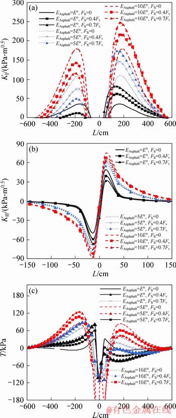
Figure 6 Variations of parameters KI (a), KII (b) and T-stress (c) versus L for different values of asphalt concrete elastic modulus and horizontal loads
FE analyses were also performed for different horizontal loads. The results of KI show that the horizontal load effect on the higher values of asphalt concrete elastic modulus is less than that on the lower values of asphalt concrete elastic modulus. For example, ratio of
 for the asphalt concrete with the elastic modulus of E��, 5E�� and 10E�� is 2.26, 1.57 and 1.38, respectively.
Results of KII for the asphalt concrete with different elastic modulus and horizontal loads are given in Figure 6(b). It is clear that increase in the elastic modulus of the asphalt concrete causes KII to increase. For example, the peak value of KII (at the wheel situations of L<0) for the cases 5E�� and 10E�� with respect to that for the case of E�� increases 38% and 51%, respectively. Also for the all cases of E��, 5E�� and 10E��, horizontal load causes KII to increase. For instance, ratio of 
 for the cases of E��, 5E�� and 10E�� is 1.35, 1.19 and 1.15, respectively. Therefore, similar to the results for KI, results of KII show that horizontal load effect on the higher values of the asphalt concrete elastic modulus is less than that on the lower values of the asphalt concrete elastic modulus.
From the results mentioned above, it can be concluded that both horizontal load and asphalt concrete elastic modulus affect KI more than KII.
Results of T-stress for different values of asphalt concrete elastic modulus and horizontal loads have been given in Figure 6(c). According to this figure, T-stress is highly affected by the asphalt concrete elastic modulus. By increasing asphalt concrete elastic modulus, T-stress increases significantly for the corresponding horizontal load, and its curve shifts to the left for L<0 (while the T-stress curve shifts to the right for L>0.
3.2.2 Elastic modulus of base layer
For all FE analyses performed in this section, mechanical properties and dimensions of the all road layers were those presented in Table 1 except elastic modulus of the base layer which was examined at three levels of E��, 5E�� and 10E��. Meanwhile, FE analyses were performed at three levels of horizontal load (Fh=0, 0.4Fv and 0.7Fv) for each base layer elastic modulus level. For the case of Fh=0, the results of KI shown in Figure 7(a) indicate that the base layer elastic modulus influence KI slightly. This figure shows that KI curve has shifted to the left and its peak value has been increased a little. For the cases that the road is loaded both vertically and horizontally (Fh=0.4Fv, 0.7Fv) and where the wheel is situated at L>0, by increasing elastic modulus of the base layer, KI decreases at the corresponding horizontal load, and this is in contrast to the results observed in Figure 6(a) for elastic modulus of the asphalt concrete layer.
Figure 7 Variations of parameters KI (a), KII (b) and T-stress (c), versus L for different values of base layer elastic modulus and the horizontal loads
FE results for KII has been plotted in Figure 7(b). This figure shows that by increasing elastic modulus of the base layer, KII decreases for all values of horizontal load. From the results for KI and KII, it can be concluded that the destructive effect of the horizontal loads at intersections, bus stations, etc. can be eliminated by performing the base layer with a material that has higher elastic modulus (for example, performing the base layer with cement concrete instead of asphalt concrete). While, the asphalt concrete performed at the top layer with higher elastic modulus resulted in higher SIFs at the crack tip (see Figure 6).
Results of T-stress for different values of base layer elastic modulus and horizontal loads have been plotted in Figure 7(c). Unlike the results for the asphalt concrete, increase of the base layer elastic modulus decreases the magnitude of T-stress for the corresponding horizontal load. Moreover, the peak value of T-stress for the all cases occurs at the same L and very near the crack.
3.2.3 Elastic modulus of sub-base layer
Figure 8 shows variations of SIFs against position of the vehicle wheel (L) for different elastic modulus of the sub-base layer and different values of the horizontal loads. Results of KI, plotted in Figure 8(a), for the case of Fh=0 show that by increasing sub-base layer elastic modulus from E�� to 5E��, the peak value of KI decreases and from 5E�� to 10E��, this value nearly remains unchanged. It is noted that by increasing the elastic modulus, KI curve shifts to the left where the wheel position is in the region L<0, and it shifts to the right where it is in the region L>0. Another point in Figure 8(a) is that increase in the sub-base layer elastic modulus causes KI to decrease at the corresponding horizontal load (similar to the results for the elastic modulus of the base layer).
Figure 8(b) shows the results for shear stress intensity factor (KII) at the crack tip. As elastic modulus of the sub-base layer increases, KII decreases (similar to the results for the base layer) at the corresponding horizontal load. Therefore, by increasing elastic modulus of the sub-base layer, SIFs at the crack tip can be reduced remarkably in particular when the road is loaded both vertically and horizontally.
Results of the FE analyses for T-stress have been presented in Figure 8(c). As is seen in this figure, where the wheel is located in L<-120 cm, by increasing elastic modulus of the sub-base layer, magnitude of T-stress decreases for the corresponding horizontal load. This manner changes at L=-120 cm and at wheel distances near the crack (or at larger L), T-stress for higher elastic modulus is more than that for lower elastic modulus.
3.2.4 Elastic modulus of sub-grade layer
Results of SIFs for different elastic modulus of the sub-grade layer and different horizontal loads have been plotted in Figure 9. As is shown in Figure 9(a), increase in elastic modulus of the sub-grade layer results in KI decrease. Meanwhile, KI curves shift to the left (for L>0). For the results of KII shown in Figure 9(b), it is clear that KII is not influenced by changing elastic modulus of the sub-grade layer. According to Figure 9(c), effect of the sub-grade layer elastic modulus on T-stress is approximately negligible, and T-stress is only affected by the horizontal load.
Figure 8 Variations of parameters KI (a), KII (b) and T-stress (c) versus L for different values of sub-base layer elastic modulus and horizontal loads
Figure 9 Variations of parameters KI (a), KII (b) and T-stress (c) versus L for different values of sub-grade layer elastic modulus and horizontal loads
By comparing the results for KI presented in Figures 6(a) to 9(a), it is observed that as increase in the elastic modulus occurs at the lower layers, KI decreases further. Also by comparing the results for KII presented in Figures 6(b) to 9(b), it is observed that as increase in the elastic modulus occurs at the lower layers, the elastic modulus effect on KII and T-stress vanishes (for example, elastic modulus of the sub-grade layer does not affect KII and T-stress). As a result, to avoid crack propagation at intersections, bus stations, etc. one may suggest that a material with lower elastic modulus should be performed at the top layer of the road structure (for example, utilizing the modified asphalt concrete mixtures), and a material with higher elastic modulus at the base layer (for example, utilizing the cement concrete instead of the asphalt concrete). Here, this point must be paid attention that asphalt concrete with lower elastic modulus may lead to another pavement deterioration so-called rutting. Therefore, a balancing act must be made to select a proper elastic modulus for the asphalt concrete to reduce the both major problems namely cracking and rutting.
3.3 Thickness of road layers
In this section, effect of the thickness of road layers including asphalt concrete, base and sub-base on the SIFs and T-stress is studied. Similar to the elastic modulus, thickness of the layers was examined at three levels. Thickness of the examined layer would be explained below, and thickness of the other layers were kept fixed at the values presented in Table 1. Moreover, investigations were developed for the horizontal loads Fh at the three levels of 0, 0.4Fv and 0.7Fv along with the vertical load.
In the first step of this section, the asphalt concrete layer with the thicknesses 14, 20 and 27 cm was modeled and analyzed using ABAQUS. Results of SIFs are shown in Figure 10. As thickness of the asphalt concrete layer increases, KI decreases. This thickness effect is significant when the road is loaded both horizontally and vertically. Moreover, increase in the asphalt concrete thickness leads to KII decrease. Results of T-stress have been plotted in Figure 10(c). By increasing the asphalt concrete thickness, T-stress decreases for the corresponding horizontal load, and T-stress more decreases for higher values of the horizontal load.
In the next step, thickness of the base layer was selected 20, 27 and 34 cm. By increasing thickness of the base layer, KI for all cases of the horizontal load decreases (see Figure 11(a)).
According to Figure 11(b), KII is not sensitive to thickness of the base layer. Figure 11(c) shows the results of T-stress for the different base layer thicknesses and horizontal loads. It is clear that T-stress is not sensitive to the thickness variations and only depends on the horizontal load level.
Figure 10 Variations of parameters KI (a), KII (b) and T-stress (c) versus L for different values of asphalt concrete thickness and horizontal loads
Finally, thickness of the sub-base layer was evaluated. The base-layer with the thicknesses 25, 35 and 45 cm was analyzed using ABAQUS modeling, and the results showed that KI decreases as the thickness of this layer increases (see Figure 12(a)). Similar to the results for the base layer, KII is not sensitive to the thickness of sub-base layer (see Figure 12(b)). Figure 12(c) shows the results of T-stress for different sub-base thicknesses and horizontal loads. Similar to the results for the base layer, T-stress is not sensitive to the thickness variations and only depends on the magnitude of the horizontal load.
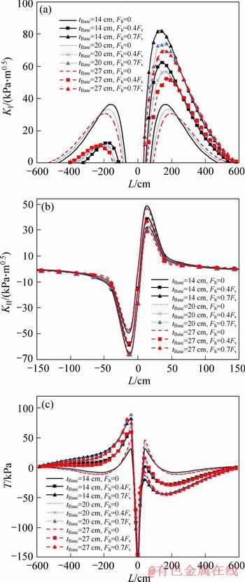
Figure 11 Variations of parameters KI (a), KII (b) and T-stress (c) versus L for different values of base layer thickness and horizontal loads
Our results showed that by increasing thickness of the road layers, SIFs at the crack tip are reduced; while, this increase in the layer thickness leads to the increase in costs of the road construction. Therefore, a trade-off should be made between them to select a proper decision. Generally, by comparing the results in Figures 10 to 12, it is observed that KI and KII are more affected by the asphalt concrete thickness than thickness of the base and the sub-base layers.
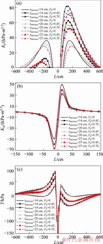
Figure 12 Variations of parameters KI (a), KII (b) and T-stress (c) versus L for different values of sub-base layer thickness and horizontal loads
4 Conclusions
1) Passing a vehicle on a cracked road creates opening (KI) and shear (KII) deformation modes as well as T-stress at the crack tip. Generally, by approaching the vehicle wheel towards the crack, the values of KI, KII and T-stress initially increase and then decrease.
2) For the cases that the vehicle wheel is positioned near the crack plane, only the shear deformation mode is observed at the crack tip. While, for the vehicle wheel positions far from the crack, only the opening mode is observed, and between these positions, both the opening and shear deformation modes (i.e., mixed mode I/II) are observed at the crack tip.
3) By increasing the horizontal load, KI increases significantly. Presence of the horizontal load with the values of 0.2Fv, 0.4Fv and 0.7Fv increases the peak value of KI by 34%, 72%, and 125%, respectively.
4) Presence of the horizontal loads at the areas before the crack (for L<0) causes the value of KII to increase; while for L>0, KII decreases. Horizontal load with the values of 0.2Fv, 0.4Fv and 0.7Fv increases the peak value of KII by 10%, 20%, and 35%, respectively.
5) By increasing the horizontal load, T-stress increases remarkably when the wheel is located at the left side of the crack plane, while it behaves in an opposite manner when the wheel is situated at the right.
6) Increase in the elastic modulus of the asphalt concrete, increases the values of KI, KII and T-stress significantly. Increase in the elastic modulus of the base layer result in a slight increase of KI and the decrease of KII and T-stress. By increasing the elastic modulus of the sub-base and sub-grade layers, KI decreases and KII is not nearly affected. Moreover, by increasing the elastic modulus of the sub-grade layer, T-stress is not affected.
7) The results of KI, KII and T-stress show that the horizontal load effect on the higher values of the asphalt concrete elastic modulus is less than that on the lower values of the asphalt concrete elastic modulus.
8) Increase in the thickness of the road layers result in the reduction of SIFs and T-stress. In addition, the SIFs as well as T-stress are more affected by the asphalt concrete thickness than the base and the sub-base thicknesses.
References
[1] KLEEMANS C P, ZUIDEMA J, KRANS R L, MOLENAAR J M M, TOLMAN F. Fatigue and creep crack growth in fine-sand asphalt materials [J]. Journal of Testing and Evaluation, 1997, 25(4): 424-428. DOI: 10.1520/ JTE11879J.
[2] MOLENAAR A A A. Prediction of fatigue cracking in asphalt pavements: Do we follow the right approach? [J]. Transportation Research Record: Journal of the Transportation Research Board, 2007, 2001(1): 155-162. DOI: 10.3141/2001-17.
[3] GARZON J, DUARTE C A, BUTTLAR W G. Computational simulations of a full-scale reflective cracking test [C]// FAA Airport Technology Transfer Conference. Atlantic City, New Jersey, USA, 2010: 3-5. https://trid.trb. org/view/1420360.
[4] MOLENAAR A A A. Fatigue and deflection cracking due to traffic loads (with Discussion) [C]// Association of Asphalt Paving Technologists. 1984, 53: 440-474. https://trid.trb.org/ view/725970.
[5] SEUNG W L, JAE M B, SEUNG H H, SHELLEY M S. Evaluation of optimum rubblized depth to prevent reflection cracks [J]. Journal of Transportation Engineering, 2007, 133(6): 355-361. DOI: 10.1061/(ASCE)0733-947X(2007) 133:6(355).
[6] AL-QADI I, WANG H. Evaluation of pavement damage due to new tire designs [R]. Research Report ICT-09-048, 2009. https://www.ideals.illinois.edu/handle/2142/13925.
[7] EMERY J. Mitigation of asphalt pavement top-down cracking[C]// 4th International SIIV Congress. Palermo, Italy, 2007. http://www.siiv.net/site/sites/default/files/Documenti/palermo/63_2848_20080108102227.pdf.
[8] MOLENAAR J M M, MOLENAAR A A A. Fracture toughness of asphalt in the semi-circular bend test [C]// 2nd Eurasphalt and Eurobitume Congress. Barcelona, Spain, 2000: 509-517. https://trid.trb.org/view/673956.
[9] TEKALUR S A, SHUKLA A, SADD M, LEE K W. Mechanical characterization of a bituminous mix under quasi-static and high-strain rate loading [J]. Construction and Building Materials, 2008, 23(5): 1795-1802. DOI: 10.1016/ j.conbuildmat.2008.09.021.
[10] WAGONER M P, BUTTLAR W G, PAULINO G H. Disk-shaped compact tension test for asphalt concrete fracture [J]. Experimental Mechanics, 2005, 45(3): 270-277. DOI: 10.1007/BF02427951.
[11] AYATOLLAHI M R, PIRMOHAMMAD S. Temperature effects on brittle fracture in cracked asphalt concretes [J]. Structural Engineering and Mechanics, 2013, 45(1): 19-32. DOI: 10.12989/sem.2013.45.1.019.
[12] PIRMOHAMMAD S, KIANI A. Study on fracture behavior of HMA mixtures under mixed mode I/III loading [J]. Engineering Fracture Mechanics, 2016, 153: 80-90. DOI: 10.1016/j.engfracmech.2015.12.027.
[13] PIRMOHAMMAD S, MENGHARPEY M H. A new mixed mode I/II fracture test specimen: Numerical and experimental studies [J]. Theoretical and Applied Fracture Mechanics, 2018, 97: 204-214. DOI: 10.1016/j.tafmec.2018. 08.012.
[14] PIRMOHAMMAD S, SHABANI H. Mixed mode I/II fracture strength of modified HMA concretes subjected to different temperature conditions [J]. Journal of Testing and Evaluation, 2019, 47(5): 3355-3371. DOI: 10.1520/ JTE20180848.
[15] AMERI M, MANSOURIAN A, PIRMOHAMMAD S, ALIHA M, AYATOLLAHI M. Mixed mode fracture resistance of asphalt concrete mixtures [J]. Engineering Fracture Mechanics, 2012, 93: 153-167. DOI: 10.1016/ j.engfracmech.2012.06.015.
[16] PIRMOHAMMAD S, KIANI A. Impact of temperature cycling on fracture resistance of asphalt concretes [J]. Computers and Concrete, 2016, 17(4): 541-551. DOI: 10.12989/cac.2016.17.4.541.
[17] PIRMOHAMMAD S, BAYAT A. Fracture resistance of HMA mixtures under mixed mode I/III loading at different subzero temperatures [J]. International Journal of Solids and Structures, 2017, 120: 268-277. DOI: 10.1016/j.ijsolstr.2017. 05.010.
[18] PIRMOHAMMAD S, MAJD-SHOKORLOU Y, AMANI B. Fracture resistance of HMA mixtures modified with nanoclay and nano-Al2O3 [J]. Journal of Testing and Evaluation, 2019, 47(5): 3289-3308. DOI: 10.1520/ JTE20180919.
[19] PIRMOHAMMAD S, AYATOLLAHI M. Fracture resistance of asphalt concrete under different loading modes and temperature conditions [J]. Construction and Building Materials, 2014, 53: 235-242. DOI: 10.1016/j.conbuildmat. 2013.11.096.
[20] PIRMOHAMMAD S, MAJD-SHOKORLOU Y, AMANI B. Experimental investigation of fracture properties of asphalt mixtures modified with Nano Fe2O3 and carbon nanotubes [J]. Road Materials and Pavement Design, 2019. DOI: 10.1080/14680629.2019.1608289.
[21] PIRMOHAMMAD S, KHORAMISHAD H, AYATOLLAHI M. Effects of asphalt concrete characteristics on cohesive zone model parameters of hot mix asphalt mixtures [J]. Canadian Journal of Civil Engineering, 2015, 43(3): 226-232. DOI: 10.1139/cjce-2014-0504.
[22] PIRMOHAMMAD S, KIANI A. Effect of temperature variations on fracture resistance of HMA mixtures under different loading modes [J]. Materials and Structures, 2016, 49(9): 3773-3784. DOI: 10.1617/s11527-015-0753-9.
[23] PIRMOHAMMAD S, BAYAT A. Characterizing mixed mode I/III fracture toughness of asphalt concrete using asymmetric disc bend (ADB) specimen [J]. Construction and Building Materials, 2016, 120: 571-580. DOI: 10.1016/ j.conbuildmat.2016.05.137.
[24] PIRMOHAMMAD S, AYATOLLAHI M. Asphalt concrete resistance against fracture at low temperatures under different modes of loading [J]. Cold Regions Science and Technology, 2015, 110: 149-159. DOI: 10.1016/ j.coldregions.2014.11.001.
[25] ALIHA M. On predicting mode II fracture toughness (KIIc) of hot mix asphalt mixtures using the strain energy density criterion [J]. Theoretical and Applied Fracture Mechanics, 2019, 99: 36-43. DOI: 10.1016/j.tafmec.2018.11.001.
[26] AMERI M, NOWBAKHT S, MOLAYEM M, ALIHA M. Investigation of fatigue and fracture properties of asphalt mixtures modified with carbon nanotubes [J]. Fatigue & Fracture of Engineering Materials & Structures, 2016, 39(7): 896-906. DOI: 10.1111/ffe.12408.
[27] ALIHA M, SARBIJAN M. Effects of loading, geometry and material properties on fracture parameters of a pavement containing top-down and bottom-up cracks [J]. Engineering Fracture Mechanics, 2016, 166: 182-197. DOI: 10.1016/ j.engfracmech.2016.08.028.
[28] AYATOLLAHI M R, ALIHA M R M. Analysis of a new specimen for mixed mode fracture tests on brittle materials [J]. Engineering Fracture Mechanics, 2009, 76(11): 1563-1573. DOI: 10.1016/j.engfracmech.2009.02.016.
[29] AYATOLLAHI M R, BGHERIFARD S. Numerical analysis of an improved DCDC specimen for investigating mixed mode fracture in ceramic materials [J]. Computational Materials Science, 2009, 46(1): 180-185. DOI: 10.1016/ j.commatsci.2009.02.020.
[30] AYATOLLAHI M R, KHORAMISHAD H. Stress intensity factors for an axially oriented internal crack embedded in a buried pipe [J]. International Journal of Pressure Vessels and Piping, 2010, 87(4): 165-169. DOI: 10.1016/j.ijpvp.2010.02. 005.
[31] AYATOLLAHI M R, HASHEMI R. Computation of stress intensity factors (KI, KII) and T-stress for cracks reinforced by composite patching [J]. Composite Structures, 2007, 78(4): 602-609. DOI: 10.1016/j.compstruct.2005.11.024.
[32] ZHOU F, HU S, HU X, SCULLION T. Mechanistic- empirical asphalt overlay thickness design and analysis system [R]. Report No. FHWA/TX-09/0-5123-3. Texas: Texas Transportation Institute,The Texas A&M, University System, College Station, 2008. https://rosap.ntl.bts.gov/view/ dot/16982.
[33] HYUNWOOK K, BUTTLAR W G, CHOU K F. Mesh-independent fracture modeling for overlay pavement system under heavy aircraft gear loadings [J]. Journal of Transportation Engineering, 2010, 136(4): 370-378. DOI: 10.1061/(ASCE)TE.1943-5436.0000101.
[34] AMERI M, MANSOURIAN A, HEIDARY-KHAVAS M, ALIHA M R M, AYATOLLAHI M R. Cracked asphalt pavement under traffic loading��A 3D finite element analysis [J]. Engineering Fracture Mechanics, 2011, 78(8): 1817-1826. DOI: 10.1016/j.engfracmech.2010.12.013.
[35] AYATOLLAHI M R, PIRMOHAMMAD S, SEDIGHIANI K. Three-dimensional finite element modeling of a transverse top-down crack in asphalt concrete [J]. Computers and Concrete, 2014, 13(4): 569-585. DOI: 10.12989/cac.2014. 13.4.569.
[36] MIAO Y, HE T, YANG Q, ZHENG J. Multi-domain hybrid boundary node method for evaluating top-down crack in asphalt pavements [J]. Engineering Analysis with Boundary Elements, 2010, 34(9): 755-760. DOI: 10.1016/ j.enganabound.2010.04.002.
[37] LIANG R Y, ZHU J X. Dynamic analysis of infinite beam or modified Vlasov subgrade [J]. Journal of Transportation Engineering, 1995, 121(5): 434-443. DOI: 10.1061/ (asce)0733-947x(1995)121:5(434).
[38] NOVAK M, BIRGISSON B, ROQUE R. Near-surface stress states in flexible pavements using measured radial tire contact stresses and ADINA [J]. Computers & Structures, 2003, 81(8-11): 859-870. DOI: 10.1016/S0045- 7949(02)00413-3.
[39] UDDIN W, ZHANG D, FERNANDES F. Finite element simulation of pavement discontinuities and dynamic load response [J]. Transportation Research Record, 1994, 1448: 100-106. http://onlinepubs.trb.org/Onlinepubs/trr/1994/144 8/1448-013.pdf.
[40] ANDERSON T L. Fracture mechanics [M]. 2nd. New York: CRC Press, 1995.
[41] LYTTON R L, TSAI F L, LEE S I, LUO R, HU S, ZHOU F. Models for predicting reflection cracking of hot-mix asphalt overlays [R]. Washington DC: The National Academies Press, 2010: 669.
[42] MYERS L A, ROQUE R, BIRGISSON B. Use of two-dimensional finite element analysis to represent bending response of asphalt pavement structures [J]. International Journal of Pavement Engineering, 2001, 2(3): 201-214. DOI: 10.1080/10298430108901727.
[43] SU K, SUN L, HACHIYA Y, MAEKAWA R. Analysis of shear stress in asphalt pavements under actual measured tire-pavement contact pressure [C]// 6th ICPT. Sapporo, Japan, 2008. https://www.researchgate.net/profile/Yoshitaka_ Hachiya/publication/237452239_Analysis_of_shear_stress_in_asphalt_pavements_under_actual_measured_tire-pavement_contact_pressure/links/0deec53bf21a3acf26000000/Analysis-of-shear-stress-in-asphalt-pavements-under-actual-measured-tire-pavement-contact-pressure.pdf.
[44] THEOCARIS P S. A higher-order approximation for the T-criterion of fracture in biaxial fields [J]. Engineering Fracture Mechanics, 1984, 19(6): 975-991. DOI: 10.1016/0013-7944(84)90144-9.
[45] AYATOLLAHI M R, ALIHA M R M. Fracture parameters for a cracked semi-circular specimen [J]. International Journal of Rock Mechanics and Mining Sciences, 2004, 41: 20-25. DOI: 10.1016/j.ijrmms.2004.03.014.
[46] AYATOLLAHI M R, ALIHA M R M. Wide range data for crack tip parameters in two disc-type specimens under mixed mode loading [J]. Computational Materials Science, 2007, 38(4): 660-670. DOI: 10.1016/j.commatsci.2006.04.008.
[47] SMITH D J, AYATOLLAHI M R, PAVIER M J. The role of T-stress in brittle fracture for linear elastic materials under mixed mode loading [J]. Fatigue and Fractyre Engineering Materials and Structures, 2001, 24(2): 137-150. DOI: 10.1046/j.1460-2695.2001.00377.x.
[48] AYATOLLAHI M R, PIRMOHAMMAD S. Effect of asphalt cement type on fracture behavior of asphalt mixtures [C]// 9th International Fracture Conference. Istanbul, Turkey, 2011.
[49] CASEY D, MCNALLY C, GIBNEY A, GILCHRIST M D. Development of a recycled polymer modified binder for use in stone mastic asphalt [J]. Resources, Conservation and Recycling, 2008, 52(10): 1167-1174. DOI: 10.1016/ j.resconrec.2008.06.002.
[50] CHAMPION L, GERARD J F, PLANCHE J P, MARTIN D, ANDERSON D. Low temperature fracture properties of polymer-modified asphalts relationships with the morphology [J]. Journal of Materials Science, 2001, 36(2): 451-460. DOI: 10.1023/A:1004836814699.
[51] HESP S A M, HOARE T R, ROY S D. Low-temperature fracture in reactive-ethylene-terpolymer-modified asphalt binders [J]. International Journal of Pavement Engineering, 2002, 3(3): 153-159. DOI: 10.1080/1029843021000067809.
[52] KIM K W, KWEON S J, DOH Y S, PARK T S. Fracture toughness of polymermodified asphalt concrete at low temperatures [J]. Canadian Journal of Civil Engineering, 2003, 30(2): 406-441. DOI: 10.1139/l02-101.
[53] KIM K W, HUSSEIN M E. Variation of fracture toughness of asphalt concrete under low temperatures [J]. Construction and Building Materials, 1997, 11(7, 8): 403-411. DOI: 10.1016/S0950-0618(97)00030-5.
[54] MOLENAAR J M M, LIU X, MOLENAAR A A A. Resistance to crack-growth and fracture of asphalt mixture [C]// 6th Int RILEM Symposium on Performance Testing and Evaluation of Bituminous Materials. Zurich, Switzerland, 2003: 618-625. DOI: 10.1617/2912143772.078.
[55] QIAN Z D, LI Z, CHEN C H. Fracture criterion for mode I crack of epoxy asphalt concrete paving course of steel deck bridge pavement [J]. Zhongguo Gonglu Xuebao/China Journal of Highway and Transport, 2008, 21(5): 33-38. https://trid.trb.org/view/924197. (in Chinese)
[56] TIMM D, BIRGISSON B, NEWCOMB D. Development of mechanistic-empirical pavement design in Minnesota [J]. Transportation Research Record: Journal of the Transportation Research Boar, 1998, 1629(1): 181-188. DOI: 10.3141/1629-20.
(Edited by HE Yun-bin)
���ĵ���
������������ں��������Ƶĵ�·�ṹ����Ԫ����
ժҪ����������Ԫ�����������о���һ�־����Զ������ѷ���IJ��·�ṹ���ڱ��о��У����˿��dz������ֵĴ�ֱ�����⣬�������˳��ֵ�ˮƽ���ؼ�����������Ƶ�λ�ã����������˰���Ӧ��ǿ������(SIFs)��T-Ӧ�����ڵ����Ƽ�˲��������⣬���о��˵���ģ������װ���ȶ����Ƽ�˲�����Ӱ�졣���������ˮƽ���غ�������ؼ���������ѷ��λ�á�·���ĵ���ģ���ͺ�ȶ��ѷ��˲���(KI��KII��T-Ӧ��)������Ӱ�졣�о������֣������ֶ�λ�������渽��ʱ�����Ƽ�˴�ֻ�м��б���ģʽ��������Զ�����Ƶij���λ�ã�ֻ�۲쵽���Ƶ��ſ�ģʽ������Щλ��֮�䣬�����Ƽ��ͬʱ�۲쵽�ſ��ͼ��б���ģʽ(�����ģʽI/II)��
�ؼ��ʣ�������������������ƣ�Ӧ��ǿ�����ӣ�T-Ӧ����ˮƽ�ʹ�ֱ����
Received date: 2018-11-24; Accepted date: 2019-07-18
Corresponding author: PIRMOHAMMAD Sadjad, PhD, Associate Professor; Tel: +98-4533517030; E-mail: s_pirmohammad@uma.ac.ir; ORCID: 0000-0003-1988-1058
Abstract: In this paper, a four-layered road structure containing a top-down crack is investigated by performing finite element analyses in ABAQUS. In this study, in addition to the vertical load of a vehicle wheel, the horizontal load as well as its position with respect to the crack is also considered in the analyses, and the crack tip parameters including stress intensity factors (SIFs) and T-stress are then calculated. Moreover, influence of elastic modulus and thickness of the pavement layers on the crack tip parameters is studied. Results show that the horizontal and vertical loads along with their position with respect to the crack, elastic modulus and thickness of the road layers influence the crack tip parameters (KI, KII and T-stress) significantly. It was also found that for the cases that the vehicle wheel is positioned near the crack plane, only the shear deformation mode is observed at the crack tip; while, for the vehicle wheel positions far from the crack, only the opening mode is observed, and between these positions, both the opening and shear deformation modes (i.e., mixed mode I/II) are observed at the crack tip.
