

Dry sliding wear behavior of Al2O3 fiber and SiC particle reinforced aluminium based MMCs fabricated by squeeze casting method
WANG Yi-qi, SONG Jung-il
Department of Mechanical Engineering, Changwon National University, Changwon 641-773, Korea
Received 17 June 2010; accepted 15 August 2010
Abstract:
Al2O3 fiber (Al2O3f) and SiC particle (SiCp) hybrid metal matrix composites (MMCs) were fabricated by squeeze casting method. The tests were carried out using a pin-on-disk friction and wear tester by sliding these pin specimens at a constant speed of 0.36 m/s (570 r/min) against a steel counter disk at room temperature, 100 ��C and 150 ��C, respectively. To observe the wear characteristics and investigate the wear mechanism, the morphologies of the worn surfaces and specific wear rate were analyzed by using scanning electron microscope (SEM) and Arrhenius plots. Moreover, the effects of fiber orientation and hybrid ratio were discussed.
Key words:
metal matrix composites; dry sliding wear; wear resistance; friction of coefficient;
1 Introduction
Recently, aluminum metal matrix composites (Al-MMCs) are widely used in the field of tribology [1-2], which have superior properties compared with the monolithic materials due to hard reinforcements. Many kinds of reinforcements, such as SiC [3-9], TiB2 [10], Al2O3 [3, 11-15], SiCrFe and CrFeC [13], have been used to manufacture Al-MMCs. These composites can be used in high-speed rotating and reciprocating elements, such as pistons, connecting rods, drive shafts, brake rotors, and cylinder bores.
Various aspects of the wear behavior of MMCs have been investigated, and detailed effects of the reinforcement type, reinforcement volume fraction, hybrid ratio, and different matrices on wear have been examined. KATO [4] reported the effects of the size (5 ?m, 15 ?m, 120 ?m, and 200 ?m) of SiC particles on the wear of a Ni matrix (ductile matrix). He found that the wear resistance was improved when the size of the particles increased from 15 ?m to 200 ?m but that the wear resistance was reduced with a particle size of 5 ?m. He also found that the effects of a SiC volume fraction of approximately 10% of particles reduced the matrix wear by half. Similarly, K?K and ?ZDIN [11] reported that the wear resistance of the composites was significantly greater than that of the aluminium alloy alone. The resistance increased with an increase in the Al2O3 particle content and size and decreased with an increase in the sliding distance, the wear load and the abrasive grit size. Also, they found that the effect of Al2O3 particle size on the wear resistance was more significant than that of the particle content.
Other researchers have focused on the high-temperature sliding wear. RODRIGUEZ et al [8] investigated aluminium-lithium alloys reinforced with SiC particles. The composite transition temperature was higher than that of the unreinforced alloy. LIU et al [12] studied the high-temperature friction and wear behavior of Al2O3 and/or carbon short fibers. They found that the friction coefficient and the wear rate of the hybrid composites containing a fixed 12% Al2O3 decreased with an increase of the carbon fiber volume fraction up to 6%. In addition, the dominant wear mechanisms shifted to severe adhesion at test temperatures above the critical transition temperature.
Although SAHIN [16] reported that the wear resistance of MMCs with a normal (N) orientation of fibers was higher than that with a planar random (PR) orientation of fibers in the case of single alumina fibers reinforced aluminium-zinc-copper alloy composites for dry sliding wear, few literatures have assessed the fiber orientation of the reinforcements for the composites. The wear behavior of this kind of MMCs was not studied systematically.
Therefore, an investigation of the dry sliding wear behavior of Al2O3f/SiCp/Al hybrid aluminum alloy MMCs from room temperature to 150 ��C was carried out. The effects of the temperatures, fiber orientations, and the fiber-to-particle hybrid ratios on the wear behavior were discussed in detail. In addition, optical microscopy (OM) images of the polished surfaces were prepared to verify the fiber orientation and observe the precipitation, and scanning electronic microscopy (SEM) images of the wear surfaces were examined in an effort to understand the modes of wear.
2 Experimental
2.1 Specimen preparation
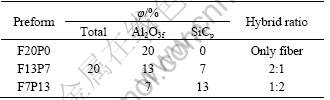
The MMC specimens were prepared by using cast aluminum alloy, A356 Al-Si, as matrix and alumina fibers (Al2O3f) and silicon carbide particles (SiCp) as reinforcing materials. In hybrid MMCs, both the reinforcing materials, Al2O3f and SiCp, were used on different proportions. The hybrid ratio of Al2O3f volume fraction to SiCp volume fraction is denoted by Fn1Pn2, where F and P indicate fiber and particle, respectively while n1 and n2 denote the percentage of fibers and particles, respectively. For unhybrid MMCs, only Al2O3f were used and their hybrid ratio was denoted by Fn1P0 (n2=0).
The preform of MMC specimens was carried out by vacuum extraction method. Table 1 shows three different categories of performs along with their hybrid ratios. For each category, the total volume fractions of the reinforcing materials were kept constant at 20 %, namely, hybrid ratios were varied by keeping the total volume fraction of the reinforcing materials constant. These performs were next used to produce ingots by squeeze casting method. The ingots were passed by heat treatment process where they were heated at 540 ��C for 4 h followed by water quenching. Later, they were artificially aged by heating at 155 ��C for 4 h followed by air cooling.
Table 1 Hybrid ratio of perform
From each category of MMC ingot, pin specimens with two different orientations of fibers, PR-orientation and N-orientation, were prepared. As shown in Fig. 1, specimens with PR-orientation of fibers are obtained when they are cut in such a way that the fibers are aligned parallel to the sliding surface of the specimen. On the other hand, specimens with normal orientation of fibers have fibers aligned in perpendicular direction to the sliding surface of the specimen. The length and diameter of pin specimens were 15 mm and 5 mm, respectively. The steel counter disk of the pin-on-disk friction and wear tester was made of 42CrMo4 and machined to 7 mm in height and 30 mm in diameter. The surfaces of pin specimens and disk were polished with 800-grit sandpaper and washed by acetone. The average roughness values of pin and disk surfaces were 0.20 and 0.13, respectively. Then, they were used in the wear testing experiment. The mass loss of the pin specimens and disk due to sliding wear was measured by a precision electronic balance having an accuracy of 0.01 mg. The results were expressed in terms of specific wear rate (mm3/(N?m)).
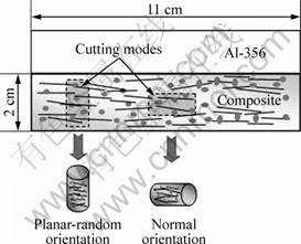
Fig. 1 Schematic of MMC ingot and pin specimens
Figure 2 shows the optical micrographs of sliding surfaces of the pin specimens with PR-orientation and N-orientation of fibers. From Fig. 2(a), it is easily observed that the fibers are lying parallel to the sliding surface of the specimen that ensures that this specimen has PR-orientation of fibers. Figure 2(b), on the other hand, shows the sliding surface of a specimen in the presence of small black spots instead of long marks. This ensures that the specimen has the N-orientation of fibers.
2.2 Condition of experiment
The wear tests were performed by using a pin-on-disk friction and wear tester. The pin specimen is held tightly against this rotating steel counter disk with the help of an applied load. In the case of the lubricant wear test, the surface of the steel counter disk was lubricated with engine oil. For the dry sliding wear tests, the steel counter disk was rotated at a constant speed of 570 r/min which was equivalent to the linear speed of 0.36 m/s at the center line of wear track of the pin specimen. For the dry sliding wear test, a constant contact load of 30 N was considered while the test was run for a total sliding distance of 2 500 m for each contact load. Moreover, these tests would be repeated at the elevated temperatures of 100 ��C and 150 ��C while a heater chamber was applied.
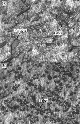
Fig. 2 Optical micrographs of PR-F13P7 hybrid MMC specimens (a) and N-F20P0 MMC (b)
3 Results and discussion
3.1 Dry sliding wear behavior at room temperature
Figure 3 displays the wear rate as a function of hybrid ratio for PR- and N-orientations of fibers.
The wear rate monotonically decreases due to the addition of SiCp for the PR-MMCs. In the case of the N-MMCs, the wear rate increases and then decreases.
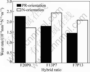
Fig. 3 Effects of hybrid ratio and fiber orientation on dry sliding wear for PR- and N-orientation fibers at room temperature
The wear resistance of F20P0 unhybrid MMCs with N-orientation of fibers is better than that with PR-orientation of fibers. The same result was observed by SAHIN [16] in an investigation of MMCs reinforced with Al2O3 fibers only.
However, the hybrid MMCs show an opposite result that the wear rate of PR-MMCs is lower than that of N-MMCs.
To understand the wear mechanisms, the worn surfaces of the specimens corresponding to the applied load of 30 N were investigated by SEM. The SEM images of worn surfaces of specimens with different hybrid ratios and fiber orientations are shown in Fig. 4. Figures 4(a) and (b) show the worn surfaces of specimens of F20P0 MMCs with PR- and N-orientations of fibers, respectively. It is observed that the worn surface of the specimen with PR-orientation of fibers has more fragmentations on the worn surface than that with N-orientation of fibers. This is due to the fact that the whole fibers were spalled out from the surface of the specimen with PR-orientation of fibers which causes the fragmentations on the worn surface, causing more mass loss. For N-orientation of fibers, the whole fibers were not pulled out. Rather, only ends of the fibers were worn out, causing less mass loss and a relatively smooth surface. The main wear mechanism is abrasive wear.
Figures 4(c) and (d) show the worn surfaces of F13P7 hybrid MMC specimens with PR- and N-orientations of fibers, respectively. The comparison of Fig. 4(a) with Fig. 4(c) shows that the F13P7 hybrid MMC specimens have fewer spalling of fibers than the F20P0 unhybrid MMC specimens. This is due to the obvious fact that the F13P7 hybrid MMC specimen contains fewer fibers than F20P0 unhybrid MMC specimen as the total volume of reinforcing materials is constant (20%). So, it is more likely that only fewer fibers spall out from the F13P7 MMC specimens with less fiber content. On the other hand, for N-orientation of fibers, the whole longitudinal surfaces of all the fibers are firmly gripped by the matrix and only the ends of the fibers come in contact with the sliding surface during wear. So, the fibers do not spall out, rather they wear out due to abrasion. When silicon carbide particles (SiCp) are added to MMCs with N-orientation of fibers, they replace some firmly gripped fibers. It is obvious that the silicon carbide particles (SiCp) on the contact surface are not as firmly gripped as fibers. Therefore, these particles are more likely to spall out during wear. As a result, the surface of F13P7 MMC specimen with N-orientation of fibers shows more fragmentations (Fig. 4(d)) than that of F20P0 MMC specimen (Fig. 4(b)). This conforms to the results shown in Fig. 3 which shows that the F13P7 MMC specimen has more mass loss than F20P0 MMC specimen due to wear.
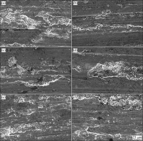
Fig. 4 SEM images of worn surfaces of MMC specimens with PR- and N-orientations of fibers at room temperature: (a) F20P0, PR-orientation; (b) F20P0, N-orientation; (c) F13P7, PR-orientation; (d) F13P7, N-orientation; (e) F7P13, PR-orientation; (f) F7P13, N-orientation
Figures 4(e) and (f) show the worn surfaces of F7P13 hybrid composite specimens with PR- and N-orientations of fibers, respectively. For PR-orientation of fibers, the further smoother surface was obtained by adding more SiCp, as seen from the comparison of Figs. 4(a) and (e). For N-orientation of fibers, the further addition of SiCp causes less number of fragmentations than previous F13P7 specimen, as seen from the comparison of Figs. 4(d) and (f).
3.2 Dry sliding wear behavior at 100 ��C
The effects of the hybrid ratio on the mass loss of the MMCs with the PR- and N-orientations of fiber for dry sliding wear at 100 ��C are illustrated in Fig. 5. The wear rate monotonically increases due to the addition of the SiCp for both the PR- and N-MMCs. It is easy to determine that the wear rate of the PR-MMC is slightly superior to that of the N-MMC for each hybrid ratio.
The morphology of the worn surfaces after 2 500 m of dry sliding wear presented in Fig. 6 was examined by SEM. The tribological characteristics were observed and the wear behavior was investigated. For F20P0 MMCs with the PR-orientation of the fibers, the fibers were easily pulled out whole from the matrix due to the different orientations of the reinforced fibers, causing a greater mass loss during dry sliding wear. This is the main cause of the considerable mass loss of the PR-MMC. From a comparison of Figs. 6(a) and (b), the wide grooves on the worn surface of the F20P0 PR-MMC can be observed. This indicates that the main wear mechanism is abrasive wear. On the worn surface of the F20P0 N-MMC, lamination defects were observed directly and the mass loss was mostly caused by adhesive wear. On the worn surface of the F13P7 PR-MMC, fragmentation was easily observable, as shown in Fig. 6(c). In the case of the F13P7 N-MMC under the same wear conditions, the characteristics of the worn surface are clearly different compared with the F13P7 PR-MMC, as shown in Fig. 6(d). Figures 6(e) and (f) illustrate the worn surfaces of the specimens of the F7P13 with PR- and N-fiber orientations, which show a great surface damage.
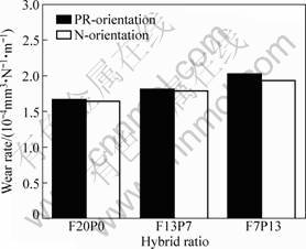
Fig. 5 Effects of hybrid ratio and fiber orientation on dry sliding wear for PR- and N-orientation fibers at 100 ��C
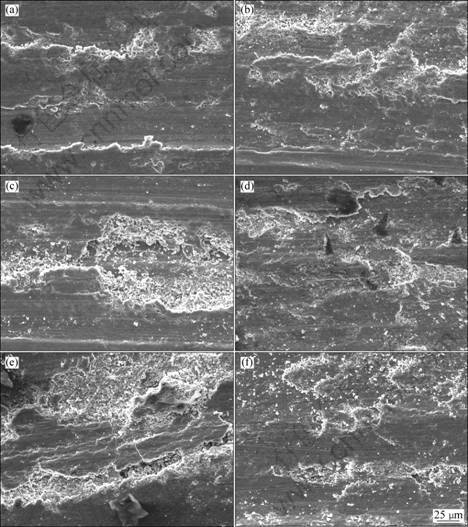
Fig. 6 SEM images of worn surfaces of MMC specimens with PR- and N-orientations of fibers after dry sliding wear at 100 ��C: (a) F20P0, PR-orientation; (b) F20P0, N-orientation; (c) F13P7, PR-orientation; (d) F13P7, N-orientation; (e) F7P13, PR-orientation; (f) F7P13, N-orientation
In a comparison of worn surfaces with PR- and N-orientations of the fibers, it was found that the worn surfaces became more damaged when the particle content was increased. Additionally, the wear worsened after dry sliding wear at 100 ��C. A reasonable explanation for these experimental results could be the synergetic action between the hardness of the reinforcements and the elevated temperature at which the tests were conducted.
Regarding the physical properties of the fiber and particle reinforcements, they were harder than the matrix. Hence, they could bear the load and attain the expected purpose of improving the wear behavior. However, for the hybrid MMCs, the wear rate increased with the increase in the particle content. It is clear that the effect of the particles is not the same as the effect of the fibers on the wear resistance. Then an explanation may be that the fibers are distributed in a form that they act like a mat, due to the fact that they have a large aspect ratio. This mat distributes the load in a large volume of the matrix, but this effect is diminished when the particle fraction increases. In other words, compared with the single fiber reinforced MMCs, the wear resistance of the hybrid MMCs declined when the composites were tested at the elevated temperature.
3.3 Dry sliding wear behavior at 150 ��C
Figure 7 displays the mass loss as a function of the hybrid ratio for both the PR- and N-orientations of the fibers. It was observed that the wear resistance of the specimens with the N-orientation of the fibers is better than that with the PR-orientation for all the three hybrid ratios. While the SiCp content increases, the mass loss increases simultaneously in both cases for the PR- and N-orientated of fibers, namely, the wear resistance decreases monotonically, and the mass loss growth trend of the specimens having the N-orientation of the fibers is lower than that with PR- orientation.
The worn surfaces of the specimens corresponding to an applied load of 30 N were also investigated by SEM, as it is useful to understand the wear mechanisms. SEM images of the worn surfaces of specimens with different hybrid ratios and fiber orientations are shown in Fig. 8. Figures 8(a) and (b) show the worn surfaces of the F20P0 MMCs specimens with the PR- and N-orientations of the fibers, respectively. In Fig. 8(a), although grooves were observed that were mainly caused by abrasive wear, the ploughing was relatively mild compared with that in Fig. 6(a). However, in this comparison, on the worn surface of the specimen with the N-orientation of the fibers, fewer grooves and more fragmentations were observed. These were caused by adhesive wear.
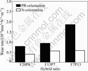
Fig. 7 Effect of hybrid ratio on mass loss of MMCs with PR- and N-orientation of fibers for dry sliding wear at elevated temperature of 150 ��C
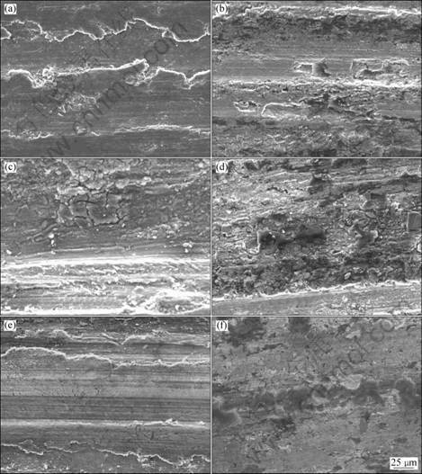
Fig. 8 SEM images of worn surfaces of MMC specimens with PR- and N-orientations of fibers after dry sliding wear at 150 ��C: (a) F20P0, PR-orientation; (b) F20P0, N-orientation; (c) F13P7, PR-orientation; (d) F13P7, N-orientation; (e) F7P13, PR-orientation; (f) F7P13, N-orientation
In the case of the F13P7 MMCs with the PR- and N-orientations of the fibers, specimens with more severe worn surfaces were observed, as shown in Figs. 8(c) and (d). The fragmentations were also observed on the worn surface of the F13P7 MMCs with the PR-orientation of the fibers. It should be noted that, after elevating the temperature to 150 ��C, more cracks were observed on the worn surfaces, especially in the case of the F13P7 MMCs with N-orientation. However, with 13 % of SiCp added, after the dry sliding wear, smoother worn surfaces were noted in both cases of the PR- and N- orientations of fibers, as shown in Figs. 8(e) and (f).
3.4 Coefficient of friction and Arrhenius plot
Figure 9 plots the variation of the coefficient of friction with the hybrid ratio of the MMCs at room temperature and elevated temperatures of 100 ��C and 150 ��C. It is found that the result of coefficient of friction tested at room temperature is similar to that at 100 ��C. The coefficient of friction decreases when the temperature increases. Furthermore, although the hybrid ratio has little effect on the coefficient of friction, the fiber orientation had a greater effect on this. The coefficient of friction of the PR-MMCs is larger than that of the N-MMCs at the same elevated temperature. In order to investigate the wear mechanism at different temperatures, Arrhenius plots were constructed by measuring the specific wear rate (mm3/(N?m)) as a function of inverse temperature (K-1), as shown in Fig. 10. It shows clearly that the activation energy of N-MMCs is larger than that of PR-MMCs. Also, compared with the cases of room temperature and 100 ��C, the activation energy is larger at 150 ��C.
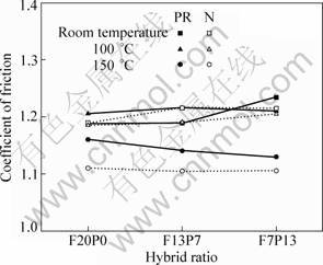
Fig. 9 Variation of coefficient of friction with orientations of fibers and temperatures in dry sliding wear
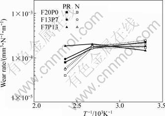
Fig. 10 Specific wear rate of MMCs as function of inverse absolute temperature (Arrhenius plot)
4 Conclusions
1) Hybrid MMCs were tested for their dry wear behaviors by a pin-on-disk friction and wear tester at room temperature and elevated temperatures of 100 ��C and 150 ��C with PR- and N-orientations of the fibers and three values of hybrid ratios.
2) Generally, the wear resistance is decreased with increasing the content of SiCp at room temperature. When the temperature increases, the SiCp does not enhance the wear resistance.
3) By comparing the PR- and N- orientations of the fibers, the fibers with the PR-orientation are easily pulled out whole from the matrix. This is the reason of the larger mass loss of the PR-MMC compared with the N-MMC. These results were also proved by the Arrhenius plot that activation energy of N-MMCs is larger than that of PR-MMCs. The wear resistance of F20P0-reinforceed MMCs at an elevated temperature is superior to that of the hybrid-reinforceed MMCs after dry sliding wear. This indicates that the wear resistance of hybrid MMCs shows a decreasing trend in both cases of the PR- and N-MMC as the content of the SiCp increases. The wear mechanism of MMCs with the PR-orientation of the fibers is abrasive, while is principally adhesive for hybrid MMCs with the N-orientation of the fibers.
Acknowledgement
This work is financially supported by Changwon National University in 2010 and the Korea Research Foundation Grant (KRF-2008-D00005) funded by the Korean Government (MOEHRD, Basic Research Promotion Fund).
References
[1] ROHATGI P. Cast aluminium-matrix composites for automotive applications [J]. Metals, 1991, 43(4): 10-15.
[2] DEUIS R L, SUBRAMANIAN C, YELLUO J M. Dry sliding wear of aluminium composites��A review [J]. Composites Science and Technology, 1997, 57(4): 415-435.
[3] WANG Y Q, AFSAR A M, JANG J H, HAN K S, SONG J I. Room temperature dry and lubricant wear behaviors of Al2O3f/SiCp/Al hybrid metal matrix composites [J]. Wear, 2010, 268(7-8): 863-870.
[4] KATO K. Wear in relation to friction��A review [J]. Wear, 2000, 241(2): 151-157.
[5] SAHIN Y. Wear behavior of aluminium alloy and its composites reinforced by SiC particles using statistical analysis [J]. Materials & Design, 2003, 24(2): 173-183.
[6] MA T J, YAMAURA H, KOSS D A, VOIGT R C. Dry sliding wear behavior of cast SiC-reinforced Al MMCs [J]. Materials Science and Engineering A, 2003, 360(1-2): 116-125.
[7] NATARAJAN N, VIJAYARANGAN S, RAJENDRAN I. Wear behaviour of A356/25SiCp aluminium matrix composites sliding against automobile friction material [J]. Wear, 2006, 261(7-8): 812-822.
[8] RODRIGUEZ J, POZA P, GARRIDO M A, RICO A. Dry sliding wear behaviour of aluminium-lithium alloys reinforced with SiC particles [J]. Wear, 2007, 262(3-4): 292-300.
[9] SAHIN Y. Tribological behaviour of metal matrix and its composite [J]. Materials & Design, 2007, 28(4): 1348-1352.
[10] ZHAO M, WU G H, JIANG L T, DOU Z Y. Friction and wear properties of TiB2P/Al composite [J]. Composites Part A: Applied Science and Manufacturing, 2006, 37(11): 1916-1921.
[11] K?K M, ?ZDIN K. Wear resistance of aluminium alloy and its composites reinforced by Al2O3 particles [J]. Journal of Material Processing Technology, 2007, 183(2-3): 301-309.
[12] LIU Y H, DU J, YU S R, WANG W. High temperature friction and wear behaviour of Al2O3 and /or carbon short fibre reinforced Al-12Si alloy composites [J]. Wear, 2004, 256(3-4): 275-285.
[13] DAS S, DAS S, DAS K. Abrasive wear of zircon sand and alumina reinforced Al-4.5wt% Cu alloy matrix composites��A comparative study [J]. Composites Science & Technology, 2007, 67(3-4): 746-751.
[14] YILMAZ S O. Comparison on abrasive wear of SiCrFe, CrFeC and Al2O3 reinforced Al2024 MMCs [J]. Tribology International, 2007, 40(3): 441-452.
[15] RAMESH C S, SAFIULLA M. Wear behavior of hot extruded Al6061 based composites [J]. Wear, 2007, 263(1-6): 629-635.
[16] SAHIN Y. Wear behavior of planar-random fibre-reinforced metal matrix composites [J]. Wear, 1998, 223(1-2): 173-183.
Ӧ��ģѹ���취�����Al2O3f/SiCp������ǿ����
���ϲ��ϵ�Ħ��ĥ����Ϊ
��һ�棬������
������ԭ������ѧ ��е����ѧԺ����ԭ 641-773������
ժ Ҫ���о���ͨ��ģѹ���췽���������������ά��̼������������ǿ�������ϲ��ϵĸ�Ħ��ĥ�����ܡ��ֱ������¡�110 ��C���Լ�150 ��C�����£������˺���0.36 m/s(570 r/min)������ʽĦ��ĥ��ʵ�顣����ɨ����������۲��ĥ���������������Arrhenius��ͼ���о����ĥ���ʣ��Ա��ڽ�һ���о�ĥ����ơ����⣬��������ά�ķ����Ժ���ά������Ļ�ϱ����á�
�ؼ��ʣ����������ϲ��ϣ��ɻ���Ħ������ĥ�ȣ�Ħ��ϵ��
(Edited by YANG Hua)
Corresponding author: SONG Jung-il; Tel: +82-55-213-3606; E-mail: jisong@changwon.ac.kr
DOI: 10.1016/S1003-6326(11)60879-0
