

Multi-pass spinning of thin-walled tubular part with longitudinal inner ribs
JIANG Shu-yong(������)1, ZHENG Yu-feng(֣���)2, REN Zheng-yi(������)1, LI Chun-feng(���)3
1. Engineering Training Center, Harbin Engineering University, Harbin150001, China;
2. Center for Biomedical Materials and Engineering, Harbin Engineering University, Harbin 150001, China;
3. School of Materials Science and Engineering, Harbin Institute of Technology, Harbin150001, China
Received 21 February 2008; accepted 21 April 2008
Abstract:
Based on the process experiments, micrography analysis was dedicated to advancing the understanding of plastic flow of the metal in backward ball spinning of thin-walled tubular part with longitudinal inner ribs. Micrography analysis reveals that severe plastic deformation leads to grain refinement, grain orientation and grain flow line of the spun part. Based on rigid-plastic finite element method, DEFORME3D finite element code was used to simulate and analyze multi-pass backward ball spinning of thin-walled tubular part with longitudinal inner ribs. Finite element simulation results involve the distributions of the strain, the shape variation of the inner ribs as well as the prediction of the spinning loading.
Key words:
finite element method; ball spinning; longitudinal inner ribs; power spinning; micrography;
1 Introduction
Tube spinning, also known as tube flow forming or tube power spinning, is a typically successively and locally plastic deformation process, which is used to produce a hollow shape product with a revolution surface by transforming a thick-walled preform into a long and thin-walled workpiece[1]. Tube spinning not only needs low load capacity and low production cost, but also manufactures components with high mechanical properties and smooth surface finish by means of less complex tooling[2-3].
As a continuous and local plastic deformation process, ball spinning belongs to tube spinning using balls as deformation tool instead of rollers[4]. However, ball spinning is characterized by its fairly small deformation zone as well as relatively low forming loads as compared with tube spinning using rollers. In addition, balls are distributed so uniformly along the circumference of deformation zone that the circumferential flow of metal in the deformation zone is confined so as to make the mandrel keep good balance and stability, which contributes greatly to enhancing the dimensional accuracy of the spun part. The ball spinning process is able to be used to manufacture the tubular part with better surface finish and larger length-to-diameter ratio as well [5-7].
The application of backward ball spinning for the fabrication of thin-walled tubular part with longitudinal inner ribs is a relatively new attempt, because the thin-walled tubular part with longitudinal inner ribs possesses a more complex spinning deformation mechanism than the counterpart without longitudinal inner ribs. The continuity and complexity of tube spinning make it difficult to understand the mechanism of plastic deformation of the process. A number of investigations with respect to the tube spinning by means of theoretical analysis and experimental method have appeared. PARK et al[8] applied the upper-bound stream-function method to the analysis of the tube spinning and consequently obtained the solution to the total power consumption required in deformation as well as the related tangential forces. In Refs.[9-12] the tube spinning process was modeled by means of elasto-plastic finite element method(FEM). XIA et al[13] utilized elasto-plastic FEM to solve the forming forces of 3D non-axisymmetric tube spinning. XU et al[14] applied 3D rigid-plastic FEM for obtaining the stress and strain-rate distribution of the deformation zone as well as explaining the mechanism of the enlarged diameter and reduced diameter of the spun tubular part. Though FEM has played a significant role in analyzing the tube spinning process, its application in simulation of backward ball spinning of thin-walled tubular part with longitudinal inner ribs has not been attempted yet. However, FEM is a powerful instrument for analyzing backward ball spinning of thin-walled tubular part with longitudinal inner ribs.
The severe plastic deformation inevitably leads to grain refinement, grain orientation and grain flow line, so the understanding of these makes a great contribution to understanding the plastic flow of the metal materials [15-16].
The present work is dedicated to combining the process experiments and FEA with micrography analysis, in order to advance the understanding of the plastic flow of the metal in backward ball spinning of thin-walled tubular part with longitudinal inner ribs.
2 Experimental
As shown in Fig.1, in the course of backward ball spinning, the spinning tooling consists of the spinning head and the mandrel. The spinning head, which consists of screw tube, supporting ring, conical ring and balls, was fixed in the chuck of the spinning lathe and turned with the principal axis of the spinning lathe. At the same time, the tubular blank was mounted on the mandrel and fed with the mandrel along the axial direction. The mandrel had grooves to form the inner ribs. The structure of the cross-section of the mandrel is shown in Fig.2. The specific dimensions of the cross-section were expressed as follows: b=3.5 mm, c=2 mm, e=2 mm and D=30 mm.
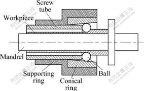
Fig.1 Schematic diagram of backward ball spinning
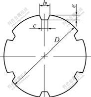
Fig.2 Schematic diagram of cross-section of mandrel
Adjusting the relative displacement between supporting ring and screw tube resulted in the different gaps between the balls and the mandrel, so the different wall thickness reduction was implemented to produce the spun part with various wall thickness and diameter.
The spinning material used in the experiment was 5A02 aluminum alloy tubes that were fabricated by cold drawing.
The spun part shown in Fig.3 was fabricated by using the tubular blank with wall thickness of 2.5 mm through three spinning passes, in which the wall thickness reduction of 0.5 mm was performed in each spinning pass.
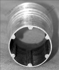
Fig.3 Photograph of spun part
3 Microstructure analysis of spun part
Analysis of microstructure of the spun part along with study of the deformation law of the grains contributes to advancing the understanding of the deformation mechanism of the spun part as well as the flow rule of the metal in the deformation zone.
In this work, specimens for microscopic observation were prepared from the original tubular blank and the various sections of the inner rib of the spun part from Fig.3 (as shown in Fig.4). Firstly, the specimens were electropolished in a electrolyte consisting of 10% HClO4 and 90% C2H5OH (volume fraction). Then, the specimens were immerged into a solution consisting of 38% H2SO4, 43% H3PO4 and 19% H2O (volume fraction) in order to fabricate film on the surface of the specimens. Finally, the microstructures of the specimens were obtained by means of polarized light microscopy (as shown in Fig.5).
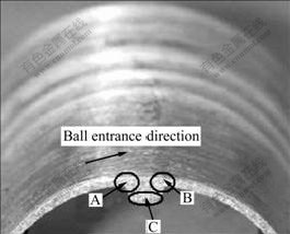
Fig.4 Schematic diagram of specimens for microscopic observation

Fig.5 Optical micrographs of tubular blank and spun part: (a) Original tubular blank; (b) Position A in Fig.4; (c) Position B in Fig.4; (d) Position C in Fig.4
It is obviously seen from Fig.5 that the microstructure of the tubular blank consists of equiaxed grains. Compared with the tubular blank, the severe plastic deformation leads to grain refinement, grain orientation and grain flow line of the spun part. The difference of grain size reveals that the plastic deformation of the spun part is inhomogeneous. The most severe plastic deformation zone where the grains are the finest is located at the wall between the two ribs. The grain size of the ribs gradually decreases in the movement direction of the ball along the circumference of the spun part because the metal of the ribs comes from various spinning passes. For instance, the grains in zone D in Fig.5(b) as well as in zone I in Fig.5(d) are obviously coarser than those in zone E in Fig.5(b) as well as in zone G in Fig.5(c). This is because the metal in zone D in Fig.5(b) as well as in zone I in Fig.5(d) should be derived from the first spinning pass, but the metal in zone E in Fig.5(b) as well as in zone G in Fig.5(c) should come from the second or the third spinning passes. What��s more, as shown in zone F in Fig.5(b) as well as in zone H in Fig.5(c), it is at the two corners of the inner rib connected with the wall of the spun part that the grain flow line shows a certain distortion, which results from the fact that the corner of the groove impedes the flow of the metal into the groove. Simultaneously, it is seen that the grain size at the two corners is inconsistent, in other words, the grains at the entrance of the ball are coarser than those at the exit of the ball. It is obviously seen from grain orientation and grain flow line that the metal flows into the groove of the mandrel along the radial and tangential directions.
4 Finite element analysis
The completion of the inner ribs of the spun part requires the large plastic deformation of the metal, so multi-pass spinning is essential for guaranteeing the reasonable forming of the inner ribs as well as the steady flow of the metal on the surface of the spun part. Because of continuity of multi-pass spinning of thin-walled tubular part with longitudinal inner ribs, namely the spun part not separating from the mandrel after each pass spinning prior to the final spinning pass, FEM presents a good approach to analyze the flow law of the metal materials as well as the shape variation of the inner ribs after each pass spinning. The commercial finite element code DEFORM3D was used to simulate the forming process of the inner ribs under multi-pass spinning.
4.1 Fundamentals of FEM
For rigid-plastic materials, the functional �� is constructed as follows:
![]() ��vidS (1)
��vidS (1)
where �� is the energy functional, ![]() is the equivalent stress and
is the equivalent stress and ![]()
![]() is the equivalent strain,
is the equivalent strain, ![]() is the equivalent strain rate, �� is the penalty factor,
is the equivalent strain rate, �� is the penalty factor, ![]() is the volume strain rate, Fi is the surface traction, and vi is a velocity field.
is the volume strain rate, Fi is the surface traction, and vi is a velocity field.
Among admissible velocities that satisfy the conditions of compatibility as well as the velocity boundary conditions, the actual solution makes the first-order variation of the functional �� vanish, namely
�Ħ�=![]() ��
��![]() ��
��![]() ��vidS=0 (2)
��vidS=0 (2)
Eq.(2) is the basic equation for the finite element discretization.
4.2 FEM model
The curve of stress��strain with respect to 5A02 aluminum alloy was obtained by means of compression test (as shown in Fig.6). The tubular blank with a length of 20 mm and a wall thickness of 2.5 mm was used as finite element model.
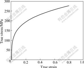
Fig.6 Stress��strain curve of 5A02 aluminum alloy
FEM model is shown in Fig.7, where the four balls are adopted in order to save the computation time. The dimensions of the cross-section of the mandrel are identical to those in the experiment. The ball has a feed movement along the axial direction as well as a revolution movement along the circumferential direction, but the mandrel is constrained. As for the tubular blank, at the entrance end of the balls the surface is free, but at the exit end of the balls it is constrained. The feed ratio of the ball is 1.6 mm/r, and the diameter of ball is 20 mm.
4.3 Finite element simulation results
4.3.1 Distributions of strain
Figs.8-10 show the finite element simulation results of backward ball spinning of thin-walled tubular part with longitudinal inner ribs through one spinning pass, two spinning passes and three spinning passes, respectively, where the wall thickness reduction of the spun part under each spinning pass is 0.5 mm.
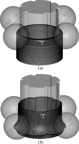
Fig.7 FEM models of backward ball spinning of spun part: (a) Before deformation; (b) After deformation
Figs.8-10 show the shape variation of the inner ribs of the spun part through three spinning passes. It is also obvious from Figs.8-10 that the inner ribs formed through one spinning pass is very shallow; the height of the inner ribs increases under two spinning passes, and the inner ribs are filled completely under three spinning passes. Furthermore, when the groove of the mandrel is not full of the metal, the inner rib shows a certain distortion, namely asymmetry.
In order to better understand the deformability of the spun part, the deformation zones can be divided into three ones, namely the build-up zone, the no-rib zone and the inner-rib zone, as shown in Fig.11, in which the strain scheme is given. It is seen from Figs.8-10 that the build-up zone is under the tensile strain in the radial and tangential direction and under the compressive strain in the axial direction. The no-rib zone is under the compressive strain in the radial direction and under the tensile strain in the axial and tangential direction. The inner-rib zone is under the tensile strain in the radial and axial direction and under the compressive strain in the tangential direction. The tensile strain in the radial direction in the build-up zone leads to the tendency of the metal to build up in front of the balls. The radial compressive strain as well as the tangential tensile strain in the no-rib zone contributes to the flow of the metal into the groove of the mandrel to form the inner ribs. The no-rib zone belongs to the severe plastic deformation zone where the severe plastic deformation leads to the grain refinement of the metal material.
4.3.2 Prediction of spinning loading
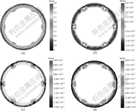
Fig.8 Distributions of strain through one spinning pass: (a) Effective strain; (b) Radial strain; (c) Tangential strain; (d) Axial strain
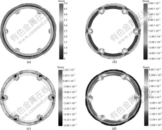
Fig.9 Distributions of strain through two spinning passes: (a) Effective strain; (b) Radial strain; (c) Tangential strain; (d) Axial strain
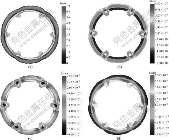
Fig.10 Distributions of strain through three spinning passes: (a) Effective strain; (b) Radial strain; (c) Tangential strain; (d) Axial strain
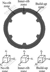
Fig.11 Strain scheme in deformable zone in spun part
The calculating results derived from FEM show that the three spinning force components, namely the radial spinning force component, the axial spinning force component and the tangential spinning force component, increase with the increase of the number of the spinning pass, as shown in Fig.12. It is very evident that the increase of the spinning force components is mainly attributed to the work hardening of the metal material under multi-pass spinning. The work hardening of the metal material has an adverse influence on the formation of the inner ribs, so it is not necessary to adopt too many spinning passes on the condition that the inner ribs are capable of being filled completely. Furthermore, during multi-pass spinning of thin-walled tubular part with longitudinal inner ribs, the proper allocation of the wall thickness reduction under each spinning pass is essential to obtain the desired spun part. The boundary friction between the inner ribs and the mandrel in the subsequent spinning pass leads to the increase of the spinning force.
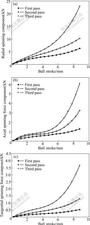
Fig.12 Variation of spinning force components vs ball stoke via multi-pass spinning: (a) Radial spinning force component; (b) Axial spinning force component; (c) Tangential spinning force
5 Conclusions
1) Multi-pass backward ball spinning is an essential approach to guarantee the steady flow of the metal material as well as the formability of the inner ribs. However, multi-pass spinning leads to the work hardening of the metal material, which has an adverse influence on the formability of the inner ribs.
2) The severe plastic deformation in backward ball spinning of thin-walled tubular part with longitudinal inner ribs leads to grain refinement, grain orientation and grain flow line. The grain orientation demonstrates that the metal flows into the groove of the mandrel along the tangential and radial directions.
3) Finite element simulation reveals the distributions of strain in different deformation zones such as no-rib zone, inner-rib zone and build-up zone. Finite element simulation results show that the three spinning force components increase with the increase of the number of the spinning pass, which indicates the occurrence of work hardening of the metal materials during multi-pass spinning.
References
[1] WONG C C, DEAN T A, LIN J. A review of spinning, shear forming and flow forming process [J]. International Journal of Machine Tools & Manufacture, 2003, 43(14): 1419-1435.
[2] CHANG S C, WANG C C, HUANG C A. Fabrication of 2024 aluminum spun tube using a thermomechnical treatment process [J]. Journal of Materials Process Technology, 2001, 108(3): 294-299.
[3] KIM C, JUNG S Y, CHOI J C. A lower upper-bound solution for shear spinning of cones [J]. International Journal of Mechanical Sciences, 2003, 45(11): 1893-1911.
[4] ROTARESCU M I. A theoretical analysis of tube spinning using balls [J]. Journal of Materials Processing Technology, 1995, 54(1/4): 224-229.
[5] ZHANG S H, LI Mao-sheng, XU Yi, KANG D C, LI Chun-zhi. Introduction to a new CNC ball-spinning machine [J]. Journal of Materials Processing Technology, 2005, 170(1/2): 112-114.
[6] JIANG Shu-yong, LI Ping, XUE Ke-min. Application of BPANN in spinning deformation of thin-walled tubular parts with longitudinal inner ribs [J]. Journal of Central South University of Technology, 2004, 11(1): 27-30.
[7] JIANG Shu-yong, XUE Ke-min, ZONG Ying-ying, YU Lin. Process factors influencing spinning deformation of thin-walled tubular part with longitudinal inner ribs [J]. Trans Nonferrous Met Soc China, 2004, 14(4): 702-707.
[8] PARK J W, KIM Y H, BAE W B. Analysis of tube-spinning processes by the upper-bound stream-function method [J]. Journal of Materials Process Technology, 1997, 67(1/3): 195-203.
[9] XUE Ke-min, LU Yan, ZHAO Xian-ming. The disposal of key problems in the FEM analysis of tube stagger spinning [J]. Journal of Materials Processing Technology, 1997, 69(1/3): 176-179.
[10] XUE Ke-min, LU Yan. Elastic-plastic FEM analysis and experimental study of diametral growth in tube spinning [J]. Journal of Materials Processing Technology, 1997, 69(1/3): 172-175.
[11] LI Ke-zhi, HAO Nan-hai, LU Yan, XUE Ke-min. Research on the distribution of the displacement in backward tube spinning [J]. Journal of Materials Processing Technology, 1998, 79(1/3): 185-188.
[12] HUA F A, YANG Y S, ZHANG Y N, GUO M H, GUO D Y, TONG W H, HU Z Q. Three-dimensional finite element analysis of tube spinning [J]. Journal of Materials Processing Technology, 2005, 168(1): 68-74.
[13] XIA Q X, CHENG X Q, HU Y, RUAN F. Finite element simulation and experimental investigation on the forming forces of 3D non-axisymetrical tubes spinning [J]. International Journal of Mechanical Sciences, 2006, 48(7): 726-735.
[14] XU Y, ZHANG S H, LI P, YANG K, SHAN D B, LU Y. 3D rigid-plastic FEM numerical simulation on tube spinning [J]. Journal of Materials Process Technology, 2001, 113(1/3): 710-730.
[15] PETRYK H, STUPKIEWICZ S. A quantitative model of grain refinement and strain hardening during severe plastic deformation [J]. Mater Sci Eng A, 2007, 444: 214-219.
[16] MORRIS D G, MUNOZ-MORRIS M A. Microstructure of severely deformed Al-3Mg and its evolution during annealing [J]. Acta Materialia, 2002, 50: 4047-4060.
Foundation item: Project(3236301154) supported by Postdoctoral Foundation of Heilongjiang Province, China
Corresponding author: JIANG Shu-yong; Tel: +86-451-82589468; E-mail: jiangshy@sina.com
DOI: 10.1016/S1003-6326(08)60255-1
(Edited by YANG Bing)
Abstract: Based on the process experiments, micrography analysis was dedicated to advancing the understanding of plastic flow of the metal in backward ball spinning of thin-walled tubular part with longitudinal inner ribs. Micrography analysis reveals that severe plastic deformation leads to grain refinement, grain orientation and grain flow line of the spun part. Based on rigid-plastic finite element method, DEFORME3D finite element code was used to simulate and analyze multi-pass backward ball spinning of thin-walled tubular part with longitudinal inner ribs. Finite element simulation results involve the distributions of the strain, the shape variation of the inner ribs as well as the prediction of the spinning loading.
