

![]()

Trans. Nonferrous Met. Soc. China 22(2012) 1182-1189
Simulation of temperature field and metal flow during continuous semisolid extending extrusion process of 6201 alloy tube
GUAN Ren-guo, ZHAO Zhan-yong, CHAO Run-ze, LIAN Chao, WEN Jing-lin
School of Materials and Metallurgy, Northeastern University, Shenyang 110004, China
Received 15 May 2011; accepted 8 November 2011
Abstract:
A continuous semisolid extending extrusion (CSEP) method was proposed. Temperature field and metal flow during continuous semisolid extending extrusion process of 6201 alloy tube were studied. During the process, the temperature in the roll-shoe cavity decreases gradually, and the isothermal lines of the alloy deviate from the shoe side to the work roll side in the roll�Cshoe gap. Metal flow velocity decreases gradually from the surface of the work roll to the surface of the shoe. In the extrusion mould, alloy temperature decreases gradually from the entrance to the exit and from the center to the sidewall of the mould. The extending cavity is radially filled with the alloy. The flow lines in the tube corresponding to the centers of the splitflow orifices and the welding gaps are dense, and the corresponding harness values are high; there are 8 transitional bands between them. In order to prepare 6201 alloy tubes with good surface quality, the pouring temperature from 750 �� to 780 �� was suggested.
Key words:
6201 aluminum alloy; semisolid; rheoforming extrusion; extending; tube; temperature;
1 Introduction
SPENCER et al [1] found rheological behaviors of semisolid metal and established the fundamental theories of rheoforming process. Subsequently, FLEMINGS [2] and KIRKWOOD [3] proposed semisolid metal processing. These findings provide a good guidance for the development of rheoforming process. Rheoforming process integrates semisolid metal preparation with slurry forming, so it is a typical short process and has many advantages, such as low cost, good deformation ability, excellent product quality, saving energy and materials. Rheoforming process has become a research focus in current metal processing field [4-6]. JI et al [7] proposed a twin-screw rheomoulding process which attracts much attention. Two typical rheoforming technologies, injection molding technique and twin-screw rheomoulding process, become mature after modification and development. However, to develop advanced rheoforming technology is till a key research object in materials forming field.
Previous study by KIUCHI and SUGIYAMA [8] showed that mushy zone exists during continuous casting and extrusion (CASTEX) of alloy, and they had prepared excellent semisolid metal slurry by using this technique. Due to the shearing and the stirring of the rotating roll, the solid phase in solidifying alloy is refined and spheroidized, and hence the excellent semisolid slurry can be prepared by this method. So, on the basis of CASTEX process, the continuous semisolid extending extrusion process (CSEP) has been developed [9-11]. A forming mould is arranged at the exit of the roll-shoe cavity, so that the slurry is extruded out from the mould and the product can be manufactured. This technique integrates slurry preparation and rheo-extrusion organically. It is a very short process and can save energy, materials and cost. In addition, big cross-section tubes and profiles could be produced by extending rheo-extrusion. Conventional splitflow extrusion mould was modified, and continuous extending rheo-extrusion of alloy product with big cross section was achieved. During continuous semisolid extending extrusion process, the distribution of mushy zone relies on the temperature field and metal flow. So, these two fields are key factors that determine the slurry quality and the success of forming process. They have important influences on the stability of forming process and the mechanical properties of products. In order to guide the designs of equipment and technology, temperature distribution and metal flow during the process should be investigated. Due to the closed type structure of the test machine, it is difficult to investigate the temperature field and metal flow only by experiment. Therefore, in the present work, the temperature field and metal flow of 6201 aluminum alloy tube during CSEP are investigated by integrating numerical simulation with experiment, and then, 6201 alloy tube with excellent surface quality is prepared.
2 Experimental and numerical simulation
2.1 Experimental
A self-designed D-350 CSEP machine was used in the experiment. The principle of the machine is shown in Fig. 1. Liquid alloy flows out of the tundish and enters the roll-shoe cavity, and it solidifies ceaselessly under the cooling by the water-cooled work roll and the shoe. Due to the actions of shearing and cooling by the roll, semisolid slurry consisting of non-dendritic solid phase and liquid phase is prepared. When the slurry meets with block, its flow direction turns 90��, so the extending mould is ceaselessly filled with the slurry. The extending cavity is firstly filled by the slurry, and then the slurry is forced to fill the welding cavity through the splitflow orifices. Finally, the slurry is forced to flow out of the channel formed by the mould orifice of the lower mould and the mould core of the splitflow mould, and the tube can be obtained. The basic technical parameters of the test machine are shown in Table 1. The structure of the extending splitflow mould with a diameter of 80 mm is shown in Fig. 2. The mould consists of the upper mould, the lower mould, the locating pins and the fitting screws. In order to compare the simulation results with the practical values, a thermal couple was inserted at the exit of the roll-shoe cavity in the shoe, and the alloy temperatures at the exit of the roll-shoe cavity under different pouring temperatures were measured.
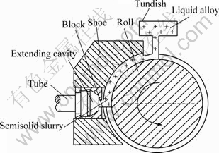
Fig. 1 Schematic diagram of continuous semisolid extending extrusion process
Table 1 Technical parameters of test machine
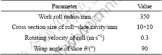

Fig. 2 Diagram of extending extrusion mould: (a) Extended die; (b) Fixed die; (c), (d) Divergent die
The experimental material was 6201 aluminum alloy which was melted by commercial pure aluminum ingots, pure magnesium ingots and Al-Si master alloy. In order to assure that alloy tubes have high comprehensive mechanical properties, alloying elements and impurity contents were strictly controlled during melting process. The chemical compositions of 6201 alloy are shown in Table 2. The solidus and liquidus temperatures of 6201 alloy were 607 and 654 ��, respectively. After being melted, the melt was refined by hexachloroethane for 3-5 min to remove the oxides, impurities and hydrogen. The melt was held for 20 min to ensure full alloying. After degassing and deslagging, the melt was held at the temperature from 740 �� to 800 ��. Meantime, CSEP mould was pre-heated to the temperature from 500 �� to 560 ��, and then the pouring began. After experiment, specimens in different positions of the tube were taken out. After specimens were polished and etched, the flow lines of the alloy were observed and the metal flow during forming was analyzed. The hardness of the tube was tested on a 450SVD Vickers optical durometer. The hardness values of the alloy in different positions were compared, and the relation of hardness distribution and metal flow was analyzed.
Table 2 Chemical compositions of experimental 6201 aluminum alloy (mass fraction, %)
![]()
2.2 Numerical simulation
The alloys in the roll-shoe cavity and in the mould cavity were taken as simulation objects. Three- dimensional finite element model was used for simulation. To reduce the amount of calculation and analyze the process conveniently, the alloy in the extending extrusion mould was divided along the central symmetric plane, and one half was taken as the simulation object, as shown in Fig. 3. In Descartes rectangular coordinate system (x, y, z), hexahedral eight-node fluid element for isotropic material was used to discrete the simulation object.
During continuous semisolid extending extrusion process of 6201 alloy tube, it was assumed that the metal obeys incompressible viscous non-Newton fluid. The rheological model can be expressed as [12]:
![]() (1)
(1)
where ��0 is the viscosity under zero shear rate; ���� is the infinite shear rate viscosity; ![]() is the shear rate; �� is the time constant; n is the power-low index.
is the shear rate; �� is the time constant; n is the power-low index.

Fig. 3 Extending rheo-extrusion path in mould (a) and simulation object in mould (b)
In order to amend the model, physical parameters of the alloy under different temperatures were input into the calculation model. The physical parameters shown in Tables 3 and 4 for calculation were adopted.
The following basic hypotheses were proposed for calculation:
1) The extrusion process was continuous stability process, in other words, the impact, leakage and flow undulation of the alloy at the initial and the finishing stages were neglected.
Table 3 Physical parameters of alloy under different temperatures
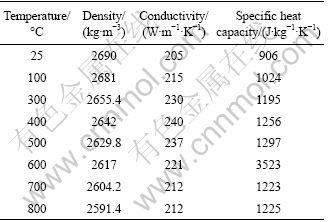
Table 4 Viscosities of 6201 aluminum alloy at different temperatures
![]()
2) The roll made of steel had a good wettability to the alloy, so the relative sliding between melt and the work roll or the shoe was neglected.
3) The melt was incompressible viscoplastic material, and the volume constancy was satisfied.
The following boundary conditions were proposed for calculation:
1) At the entrance of the roll-shoe cavity, the temperature was constant and was equal to the pouring temperature.
2) The central symmetric section in the extending extrusion mould was thermal insulation plane.
3) Contact surfaces between the alloy and the shoe, the work roll and the mould were heat transferring boundaries, and an overall coefficient of heat transfer was used to reflect the heat transfer capability of these boundaries,
q=h(T0-T1) (2)
where h is the overall coefficient of heat transfer; T0 is the alloy temperature; T1 is the surface temperature of the tool or the mould.
4) On the contact surface of the alloy and the shoe, the velocity on this surface was zero.
5) On the contact surface of the alloy and the work roll, the velocities were the linear velocity of the work roll and were loaded in three directions:
![]() ,
, ![]() ,
, ![]() (3)
(3)
where vR is the linear velocity on the groove surface of the work roll; i, j are the node number of the surfaces; �� is the angle between the vertical line from node to the axis of the work roll and xOz plane.
3 Results and discussion
3.1 Temperature distribution and metal flow in roll-shoe cavity
Isothermal line distributions and semisolid regions (654-607 ��) in the roll-shoe cavity during pouring at 720 and 740 �� are shown in Fig. 4. Figure 5 shows the comparison of simulation temperatures and measured values at the exit of the roll-shoe cavity, showing that the simulation results nearly agree with the measured values. There is a little deviation within 1.5% between them.
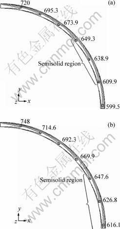
Fig. 4 Temperature distributions and semisolid regions in roll-shoe cavity under different pouring temperatures: (a) 720 ��; (b) 740 ��
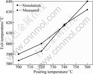
Fig. 5 Comparison of simulation temperatures and measured values at exit of roll-shoe cavity
Through Fig. 4 and Fig. 5, it is shown that, as the melt moves downwards ceaselessly, the temperature decreases gradually. The temperature near the shoe side is relatively low, and the isothermal lines of the alloy deviate from the shoe side to the work roll side in the roll�Cshoe gap. The velocity and the temperature are interactional during solidification. The changes of metal viscosity and flowing ability hence affect the velocity field. The temperatures of the work roll and the shoe which are cooled by water are low, while the pouring temperature is from 700 to 800 ��, so the temperature difference between the melt and the tool can reach 775 ��. Thus, a great temperature gradient exists between the melt and the tools. When the melt contacts with the roll and the shoe, a large supercooling occurs within a short time in the front edge of contact surface between the melt and the tools, and the melt is cooled rapidly. Because the work roll is rotary, the melt near the work roll is firstly dragged downwards by the roll. The melt near the work roll moves downwards faster than that near the shoe, so the isothermal lines of the alloy deviate from the shoe side to the work roll side in the roll�Cshoe gap.
According to the calculation results, it is known that the exit temperature is basically proportional to the pouring temperature, as shown in Fig. 5. With the increase of pouring temperature, the semisolid region moves downwards gradually. When pouring temperature is lower than 720 ��, the exit temperature is lower than the solidus temperature, so the melt fills the mould cavity in solid state, and in this case, the resistance to deformation of the solid alloy is high. In addition, a series of complex flow processes, such as extending flow, splitflow and welding extrusion, occur during deformation stage and the extrusion force is very large. So, if the pouring temperature is too low, the extrusion process will fail. Even when the pouring temperature is improved to 740 ��, because of the obstruction of the alloy due to too high solid fraction at the exit, the experiment also fails and the tube can not be obtained. When the pouring temperature is 760 ��, the alloy temperature at the filling mouth of the mould is 621 ��, as shown in Fig. 6, so the flow ability of the slurry is excellent, and hence the slurry can easily fill the forming mould. High pouring temperature is favorable for metal flow. However, if the pouring temperature is too high, the shearing action of the work roll on the alloy is weak, which is unfavorable for slurry preparation, in this case, dendrites inevitably appear. This effect has already been reported elsewhere [9-11]. When the pouring temperature is higher than 780 ��, in the case of 790 ��, the alloy temperature at the exit of the roll-shoe gap and prior to the filling mouth is 654 ��, which reaches the liquidus temperature, as shown in Fig. 7. So, the liquid metal fills the deformation zone, which not only results in the formation of as-cast microstructure inside the product but also results in bad welding of the tube and the occurrence of cracks. When the pouring temperature is 750-780 ��, semisolid metal fills the deformation zone, and good quality product can be obtained. So, the reasonable pouring temperature ranging from 750 �� to 780 �� is suggested.
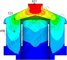
Fig. 6 Temperature field of alloy on central symmetrical plane of mould cavity at pouring temperature of 760 ��
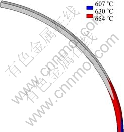
Fig. 7 Semi-solid zone at pouring temperature of 790 ��
The three-dimensional contoured velocity in the roll-shoe cavity when the roll speed is 0.3 m/s and the pouring temperature is 760 �� is shown in Fig. 8. It is shown that the velocity decreases gradually from the work roll surface to the shoe surface. The maximum velocity occurs near the work roll surface, while the minimum one takes place near the shoe surface. These results are in agreement with practical situation. The internal friction force exists among different melt layers which have different velocities. The internal friction force leads the melt to move in a laminar way under the driving of rotating work roll. MARTIN and BROWN [13] proposed a calculation formula of the internal friction shear stress of the melt among different melt layers. The shear stress caused by the internal friction is proportional to the viscosity of the melt and the velocity gradient among different melt layers. It is the shear stress that mainly results in the break-up of dendrites and the refinement of alloy microstructure, which has already been reported [9,11].
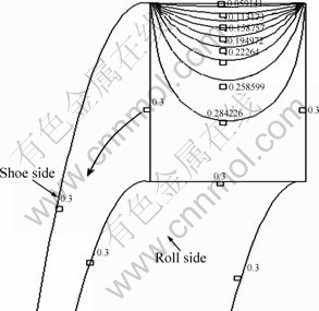
Fig. 8 Three-dimensional contoured velocity in roll-shoe cavity when roll speed is 0.3 m/s and pouring temperature is 760 ��
3.2 Temperature distribution and metal flow in extending extrusion mould
The three-dimensional temperature fields of the melt in the extending extrusion mould obtained by calculation are shown in Fig. 9. The results show that alloy temperature decreases gradually from the entrance to the exit and from the center to the sidewall of the mould. The alloy temperature around the bottom of the extrusion mould is the lowest. Due to a low flow resistance at the splitflow orifice, the temperature of the melt at the splitflow bridge is relatively low. It can be found that when the pouring temperature is lower than 740 ��, the entrance temperature in the extending cavity is lower than the solidus temperature of 607 ��. So, the alloy fills the extending cavity in solid state, and the semisolid extrusion cannot be achieved.
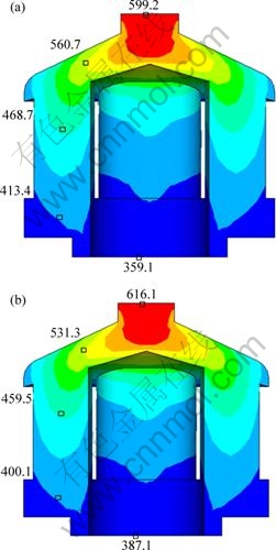
Fig. 9 Temperature fields of alloy on central symmetrical plane of mould cavity under different pouring temperatures: (a) 720 ��; (b) 740 ��
The velocity vector diagram of the alloy in the extending extrusion mould is shown in Fig. 10. It can be found that the alloy fills the extending cavity layer by layer with a radiating form, and then it is forced to flow with a splitflow form. Finally, it is forced to merge gradually around the sizing band. The metal flow velocity in the center position of the mould is the largest, and the flow velocity decreases gradually towards the side wall of the mould. The temperature of the alloy also decreases gradually. Due to the splitflow bridge and the splitflow orifice, temperature distribution displays incompletely symmetry. Due to the extension of total sectional area at the extending cavity and the splitflow orifice, the flow velocity of the melt decreases, but at the exit, due to the decrease of cross-sectional area of the sizing band, the flow velocity of the melt increases. Melt flow conforms to the volume constancy of incompressible fluid:
![]() (4)
(4)
where v0, v1 and v2 are the average flow velocities of alloy at the entrance of extending cavity, the splitflow orifice and the sizing band, respectively; S0, S1 and S2 are the cross-sectional areas at the entrance of extending cavity, the splitflow orifice and the sizing band, respectively; k is a constant.

Fig. 10 Velocity field of alloy in extrusion mould
Metals that come from two adjacent splitflow orifices are merged in the welding cavity and flow into the sizing band, and the tube is obtained. When the pouring temperature is 760 ��, the metal flow lines on the cross section in the front of the tube are shown in Fig. 11 for the specimen taken at the initial forming part of the tube. The metal flow lines at the positions corresponding to the splitflow orifices and the welding gaps are shown in this figure also. It can be seen that the flow lines at the positions corresponding to the splitflow orifices (Sp.) and the welding gaps (Wel.) are dense, there are 8 transitional bands between them, and the metal flow lines at the transitional bands (Tr.) between the welding gaps and the centers of the splitflow orifices are sparse, which is in agreement with the simulation results. In order to further validate this metal flow rule, microhardnesses in different positions were tested. The test positions and results are shown in Fig. 11 and Table 5. It can be found that the hardness values at positions 1, 4, 5, 6 and 9 corresponding to the welding gaps and the splitflow orifices are high, whereas those at positions 2, 3, 7 and 8 are low. The dense metal flow lines at the welding gaps and the centers of the splitflow orifices indicate that metal deformations are severe at these positions. So, the hardness values in these positions are high, which is in agreement with above metal flow rule.
Previous study showed that high liquid fraction is not favorable for semisolid forming [14,15]. Similar to this rule, during CSEP process, high pouring temperature worsens the mechanical properties of product or results in bad welding of the product. According to the results of the experiments, when the pouring temperature was 740 ��, the obstruction in the deformation mould usually happened, which caused process failure, as shown in Fig. 12(a). When the pouring temperature reached 790 ��, even the process was successful, there was obvious fracture occurring on the product, as shown in Fig. 12(b). The quality of 6201 alloy tube produced at the pouring temperature of 750 �� is good, as shown in Fig. 12(c). It is shown by the simulation and the experiment that, the reasonable pouring temperature is from 750 �� to 780 ��.
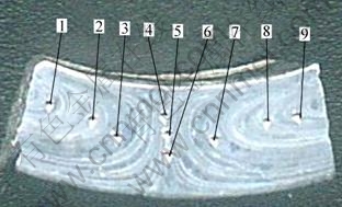
Fig. 11 Positions on cross section of 6201 tube for hardness test
Table 5 Hardness of 6201 tube on cross section

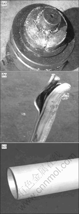
Fig. 12 Deformation status of 6201 alloys tube under different pouring temperatures: (a) 740 ��; (b) 790 ��; (c) 750 ��
4 Conclusions
1) During continuous semisolid extending extrusion of 6201 alloy tube, the temperature in the roll-shoe cavity decreases gradually, and the isothermal lines of the alloy deviate from the shoe side to the work roll side in the roll�Cshoe gap. Metal flow velocity decreases gradually from the surface of the work roll to that of the shoe.
2) Alloy temperature decreases gradually from the entrance to the exit of the mould and from the center to the sidewall of the mould. The extending cavity is radically filled with the alloy.
3) The flow lines in the tube corresponding to the centers of the splitflow orifices and the welding gaps are dense, and the corresponding hardness values are high, there are 8 transitional bands between them.
4) In order to prepare 6201 alloy tubes with good surface quality, the pouring temperature from 750 �� to 780 �� is suggested.
References
[1] SPENCER D B, MEHRABIAN R, FLEMINGS M C. Rheological behavior of Sn-15pct Pb in the crystallization range [J]. Metallurgical Transactions A, 1972, 3(7): 1925-1932.
[2] FLEMINGS M C. Behavior of metal alloys in the semisolid state [J]. Metallurgical Transactions A, 1991, 22(5): 957-781.
[3] KIRKWOOD D H. Semisolid metal processing [J]. International Materials Reviews, 1994, 39(5): 173-178.
[4] YANG Xiang-jie, GUO Hong-min. Developing tendency and countermeasures of rheoforming slurry-making [J]. Special Casting and Nonferrous Alloys, 2004(6): 1-4. (in Chinese)
[5] TANG Guo-xing, MAO Wei-min, LIU Yong-feng. Research progress on rheoforming technology of semi-solid alloy [J]. Foundry Technology, 2007, 28(5): 709-713. (in Chinese)
[6] MAO Wei-min, BAI Yue-long, GAO Song-fu, TANG Guo-xing. Research on the composite slurry preparation and rheocasting of aluminum alloy [J]. Diffusion and Defect Data B: Solid State Phenomena, 2006, 116-117: 410-416.
[7] JI S, FAN Z, BEVIS M J. Semisolid processing of engineering alloys by a twin-screw rheomoulding process [J]. Materials Science and Engineering A, 2001, 299: 210-217.
[8] KIUCHI M, SUGIYAMA S. A new process to manufacture semisolid alloys [J]. ISIJ International, 1995, 35(6): 790-797.
[9] GUAN Ren-guo, WANG Shun-cheng, WEN Jing-lin. Continuous semisolid extending extrusion process for producing AA2017 aluminum alloy flat bar [J]. Materials Science and Technology, 2006, 22(6): 706-712.
[10] GUAN Ren-guo, WEN Jing-lin, LIU Xiang-hua. FEM analysis of aluminium alloy 2017 thermal/fluid multiple fields during a single roll stirring process [J]. Materials Science and Technology, 2003, 19(4): 503-506.
[11] GUAN Ren-guo, ZHAO Zhan-yong, SUN Xiao-ping, HUANG Hong-qian, DAI Chun-guang, ZHANG Qiu-sheng. Fabrication of AZ31 alloy wire by continuous semisolid extrusion [J]. Transactions of Nonferrous Metals Society of China, 2010, 20(s3): 729-733.
[12] CHEN Wen-fang. Some constitutive equations for non-Newtonian fluids [J]. Acta Mechanica Sinica, 1983(1): 16-26.
[13] MARTIN C L, BROWN S B, FAVIER D, SUERY M. Shear deformation of high solid fraction (>0.6) semisolid Sn-Pb under various structures [J]. Materials Science and Engineering A, 1995, 202: 111-122.
[14] TAHAMTAN S, FADAVI B A. Microstructural characteristics of thixoforged A356 alloy in mushy in mushy state [J]. Transactions of Nonferrous Metals Society of China, 2010, 20(s3): 781-787.
[15] WATARI H, DAVEY K, RASGADO M T, HAGA T, IZAWA S. Semi-solid manufacturing process of magnesium alloys by twin-roll casting [J]. Journal of Materials Processing Technology, 2004, 155-156: 1662-1667.
6201���Ͻ�ܲ�����������չ��ѹ������
�¶ȳ�����������ֵģ��
���ʹ�����ռ�£��������� �����¾���
������ѧ ������ұ��ѧԺ������ 110004
ժ Ҫ������������Ƶ��������̬��չ��ѹ����װ���Ʊ�6201���Ͻ�ܲģ���������ֵģ���о��˹��̵��¶ȳ��������ֲ����ɡ������������-ѥ��ǻ�ںϽ���¶ȴ���ڵ����ڴ����ͣ���������������ƫ�ƣ����������ٶ��ع������������ѥ�������εݼ�������չ��ѹģ���ڣ��Ͻ�ʷ���״��䵽ģ���У��¶�����ڵ����ڴ����ͣ���ģ����չǻ���ĵ��¶ȸ��ڱ�����¶ȡ�����������λ�úͺ��ϲ�λ��Ӧ�ij��ιܲĽ��������ܼ����˴���Ӧ�Ľ���Ӳ��Ҳ�ߣ�������֮�����8�����ߵ��滺���ɴ���Ϊ�Ʊ������������õ�6201���Ͻ�ܲģ������Ľ�ע�¶�Ϊ750~780 �档
�ؼ��ʣ�6201���Ͻ𣻰��̬��������Σ���չ��ѹ���ܲģ��¶�
(Edited by YANG Hua)
Foundation item: Projects (51034002, 50974038) supported by the National Natural Science Foundation of China; Project (132002) supported by the Fok Ying Tong Education Foundation; Project (2011CB610405) supported by National Basic Research Program of China
Corresponding author: GUAN Ren-guo; Tel: +86-24-83681463; E-mail: guanrg@smm.neu.edu.cn
DOI: 10.1016/S1003-6326(11)61303-4
Abstract: A continuous semisolid extending extrusion (CSEP) method was proposed. Temperature field and metal flow during continuous semisolid extending extrusion process of 6201 alloy tube were studied. During the process, the temperature in the roll-shoe cavity decreases gradually, and the isothermal lines of the alloy deviate from the shoe side to the work roll side in the roll�Cshoe gap. Metal flow velocity decreases gradually from the surface of the work roll to the surface of the shoe. In the extrusion mould, alloy temperature decreases gradually from the entrance to the exit and from the center to the sidewall of the mould. The extending cavity is radially filled with the alloy. The flow lines in the tube corresponding to the centers of the splitflow orifices and the welding gaps are dense, and the corresponding harness values are high; there are 8 transitional bands between them. In order to prepare 6201 alloy tubes with good surface quality, the pouring temperature from 750 �� to 780 �� was suggested.
