

Plastic flow pattern and its effect in
friction stir welding of A2024 and A1060
WANG Xi-jing(��ϣ��), ZHANG Zhong-ke(���ҿ�), LI Jing(�� ��), DA Chao-bing(�ﳯ��)
State Key Laboratory of Gansu Advanced Non-ferrous Metal Materials,
Lanzhou University of Technology, Lanzhou 730050, China
Received 28 July 2006; accepted 15 September 2006
Abstract:
During the friction stir welding (FSW), the property of the welding joint is highly affected by the plastic and viscous flow behavior of the softened material. The flow pattern of the welded material was examined through observing the microstructural distribution of friction stir welded joints between dissimilar 2024 and 1060 aluminum alloy. The experimental results show that the flow patterns of material at different locations in the weld are different and can be divided into four layers along the thickness direction: surface flow layer influenced by the shoulder of the tool, in which the material tends to flow as integrity; horizontal flow layer influenced by the surface flow layer, in which the material of surface flow layer enters and flows forwards under the advancing force of the tool; vertical flow layer (plastic flow area induced by stirring of the pin), in which the flow pattern is complex and onion rings can often be observed; unstirred bottom layer because of the length of the pin being shorter than the thickness of the plates. The effect of plastic flow on welding quality was further investigated. The study suggests that welding quantity is significantly influenced by the flow pattern and defects always appear in horizontally lamellar flow region because of the complex flow pattern.
Key words:
friction stir welding; dissimilar metals; flow pattern; welding defects;
1 Introduction
Friction stir welding (FSW) is a new solid-state joining technique. In the process of FSW, the material to be welded is plasticized by the heat generated at the contact area between rotating tool and workpiece. Under the thermo-mechanical function the flow of the welded material is implemented and the quality of the joint is affected by the flow pattern of the material directly.
Study of flow field is an important aspect in the study of FSW as it has theoretical significance to realize the mechanism of the welding figuration and to analyze the factors of the welding defects, and it also has practical value to optimize processing technology and to control the quality of the joint.
At present, many domestic and foreign researchers study on the process of friction stir welding (FSW) in order to visualize the flow of the plastic material, and many methods have been put forward. BLAIR et al[1], YING et al[2-3] and SEIDEL et al[4] provided the measured results of flow field by many methods such as marker inserted technique, and marker tracked technique. In Refs.[5-7] the influence of flow field on the welding properties in aluminum alloys was given from a microstructure point of view. The division of plastic material flow field in FSW was completed, and the characteristics of some zones were also analyzed[8-12]. The model of the fluid was established by XU[6], and SEIDEL [9]. The domestic current basic situation of the study on flow field was provided[13-15].
However, an explanation of the relationship between the flow characteristics and the defects of the dissimilar materials by FSW is not concerned. In this article some experimental results of two different kinds of aluminum alloys are presented, and the weld is made into samples after FSW. The flow property of the friction stir welded material is observed by contrasting the obvious different shapes of the microstructure of the two aluminum alloys after etching. The distribution of the dissimilar alloys at different location of the weld is observed and the flow pattern is visualized by the differential etching of the two aluminum alloys. The flow pattern of the welded material and the effect of the flow pattern on welding quality during the FSW process are established.
2 Experimental
The plate was 300 mm��100 mm��4 mm in dimension and the nominal chemical compositions and properties are listed in Table 1. The 1060 aluminum alloy was put at the advancing side and the 2024 aluminum alloy at the retreating side in the experiment.
Based on the previous experiments, an optimum welding parameter (traverse speed: 120 mm/min, rotational speed: 1 050 r/min) was chosen. After FSW, longitudinal specimens at different locations of the weld (the center of the weld, 2 mm toward the advancing side and 2 mm toward retreating side) were cut according to the requirement of the metallographic observation. Metallographic specimens were polished and etched using a Keller��s reagent (HCl 15 mL, HNO3 5 mL, HF 1 mL, adding H2O to 50 mL) and the microstructure were observed by Mef3 optical microscope (OM). Since the corrosion resistance of A1060 was stronger than that of A2024, the microstructure of A1060 was shiny and that of A2024 was dim under OM after etching for the same time using the same reagent. So the alternately dark and bright structure could be observed in the specimen. The flow behavior of the welded material during the welding process could be analyzed through the distribution of the two microstructures in the cross-section.
3 Results and discussion
3.1 Flow pattern of longitudinal section
During FSW process, downward force generated by shoulder of the tool is applied to the welded material along the vertical direction. Tangential forces generated by rotation of the pin, horizontal pressure along the welding direction, friction force between the pin and the welded material, and between the surface of the shoulder and the surface of the welded plates are applied to the welded material along the horizontal direction. Under the combined action of these forces, plastic flow of softened material occurs and the flow pattern shown in Fig.2 is formed finally. It is indicated from Fig.2 that four layers exist obviously along the thickness direction of the welded material (A, B, C, D in Fig.2(a) correspond to those in Fig.2(b)). A is the surface flow layer; B is the region in which material flows horizontally; C is the region in which material flows vertically, and is also the onion ring area if onion ring is observed at the traverse section; and D is the region in which material is unstirred. Due to the friction heat between the surface of the tool shoulder and the surface of the plates, the material in region A is much more soft than others in the interior of the welding. So material in region A moves firstly under the friction force of the tool shoulder, and the superficial material of this region flows rotational forwardly integrally due to the drive of the shoulder. Besides the horizontal friction force and vertical force downward are also applied to the superficial material. Meanwhile, lower level material which flows latter hampers the flow of the superficial material. The part of the superficial material which is not taken away under the combined action of these two aspects enters the interior of the welding downward, and the horizontal flow tendency corresponds to the welding direction. Magnification of region A is shown in Fig.3(a). Material in region B influenced by the flow of the superficial material has a tendency to flow horizontally, as magnified in Fig.2(b). Heat input of this area mainly consists of friction heat between pin and welded material and friction heat between tool shoulder and superficial material transferred by superficial material.
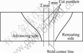
Fig.1 Longitudinal specimens at different locations
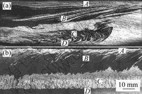
Fig. 2 Flow pattern of welded material: (a) Traverse section; (b) Longitudinal section
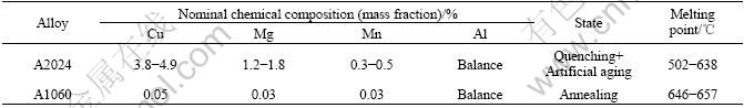
Table 1 Nominal chemical compositions and properties of 2024 and 1060 aluminum alloys
Due to the difference of the heat input, temperature rise and plastic flow of material in this region both happen later than the superficial material. Material in this region can not flow together with the superficial material because its softening level is not as well as that of region A at the same time during the welding. The rotational force of the pin applied to the surrounding material in this region makes the material tend to flow upward around the pin, but the driving action of the superficial material and the function of the shoulder make the material tend to flow downward and horizontal forward. So, the observed disordered area of intersect layers (shown in Fig.2(b)) and irregular laminar flow pattern in region B are totally attributed to the combined action of these factors. The depth that superficial material is pressed is finite due to the decrease of force of the shoulder on this region, and laminar flow pattern does not exist in the material at the lower level of region B. Region C is the vertical lamellar flow region affected by the pin, and is also the onion ring area if onion ring is observed at the traverse section. Obvious demarcation line can be observed between region B and C due to the different flow patterns, as shown in Fig.2. It can be considered that there are only extrusion force and tangential force of the rotational advancing pin applied to the material in region C, because the influence of the friction heat and force between the shoulder and the superficial material on this region far from the surface is negligible. Under this stress state, this part of material is easy to move together with the rotational advancing pin. Since the temperature of the material in front of the pin is lower than that in the back[14], the ��hard�� material at front will hamper the rotational advance of the plastic material and scale off the thin lamellar material from the pin. Therefore, the vertical laminated flow formed in region C is the results of the periodic movement of the material discussed early, as magnified in Fig.3(c). At the same time, uneven quantity of white and black phases is observed in region C because of the varied yield strength of the continuous phase and discrete phase in the traveling of the plastic material surrounding the pin. The difference of the yield strength affects the friction traveling and recrystallization of the plastic material and leads to the rheologic inhomogeneity of the material in the multi-sheet structures[15]. During FSW, the length of the pin is shorter than the thickness of the welded plates so as to prevent the contact of the pin and the backing plate. Region D, in which the material is unstirred, is formed at the bottom of the weld. It is indicated in Fig.2 that obvious demarcation line between region C and D can be observed.
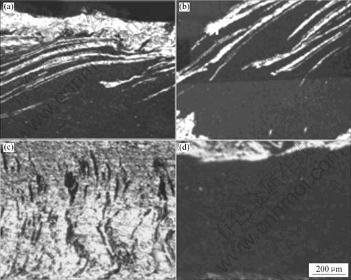
Fig.3 Magnification of region A, B, C, D in Fig.2: (a) Region A; (b) Region B; (c) Region C; (d) Region D
Base material at the bottom of the pin restrains the flow of the softened material around the end of the pin because the base material in this region is unstirred by the pin, so this part of softened material flows in an extrusion pattern instead of shear pattern. Obvious flow pattern can not be observed in region D, as shown in Fig.3(d).
3.2 Contrast analysis of flow pattern at different locations of weld
Longitudinal sections at the center, advancing side and retreating side are analyzed interdependently, as shown in Fig.4, and different flow pattern at different locations can be obtained. Since the friction coefficient of the softer material is increased under high temperature, the softer material adhering to the shoulder is easier to flow, so almost the whole surface of the weld is covered by A1060 alloy. Obvious demarcation line between region A and B at advancing side and retreating side can be observed in the magnified morphology in Fig.5. Region A is the layer of pure aluminum flowed integrally and irregular flow is observed in the upper layer of region B. The trends of both lamellar flowed materials are forward and downward, while irregular lamellar flow at advancing side is more obvious. At the longitudinal section, demarcation line between region A and B, and the irregular flow at both sides are not obvious. Since the pin is located in the center line, the force of shoulder can not be extended to the materials in this area, and flow pattern under shoulder force can not be seen. In region C, material flows laminated vertically at various locations of the weld and the pattern at the center line is most prominent. Region C is called serrated-area or plastic flow area induced by stirring in some other documents. Magnified morphologies of region C at the three locations are also shown in Fig.5. It can be seen that the flow patterns of region C at the three locations are not completely same. Regular laminated flow pattern is observed at the center line in Fig.5(a) and the interlamellar spacing is approximately 30 ��m. The calculated advancing distance which the pin rotation advances one circle is 114 ��m, so the interlamellar spacing generated by the flowing of the material is less than the calculated advancing distance. It can be concluded that during the plastic flow of the plastic material at the center line of the weld, equiaxed grain structure is formed by recrystallization due to the higher heat input. Since the force generated by stirring of the pin is significant, material reaches a homogeneous mixing state by laminar and alternative transition. The flow of the plastic material is made more smoothly by the lamellar structure and good flow performance between layers [13], and ideal welding quality is obtained. During FSW, temperature in front of the pin is lower than that in back, so material at both two sides of the pin is driven to flow forward seriously than backward. At the retreating side, laminated structure is observed obviously because the flow direction of the material is concordant with the rotational direction of the pin. But the spacing of the lamellar material at the retreating side is approximately 200 ��m, which is larger than the advancing distance of one rotation of the pin.
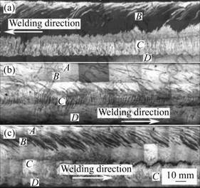
Fig.4 Longitudinal section morphologies at varied locations of weld: (a) Retreating side; (b) Center; (c) Advancing side
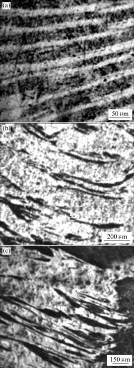
Fig.5 Magnified morphologies of region C at varied locations of weld: (a) Weld center; (b) Retreating side; (c) Advancing side
At the advancing side, as the pin rotation advances, a sheet of the material at the edge of the pin flows along the welding direction, while most material is extruded backward by the advancing movement of the pin and flows opposite to the welding direction. So, the mixed disordered material at the advancing side is exhibited, and laminar and alternative flow is not obvious, as shown in Fig.5(c).
3.3 Effect of plastic flow on welding quality
In order to study the effect of plastic flow on welding quality under varied welding technology further, specimens cut from joints welded under varied transverse speeds were analyzed. Longitudinal sections welded at rotation speed of 1 050 r/min and varied transverse speeds are shown in Fig.6. It can be seen from Fig.6(b) that non-defect joint is generated when rotation speed of 1 050 r/min and transverse speed of 120 mm/min are chosen, because plastic material flows smoothly under the heat and force generated under these welding parameters. Longitudinal section view at a rotation speed of 1 050 r/min and a transverse speed of 140 mm/min is shown in Fig.6(a). Since the transverse speed is high, the time that material stays at high temperature is short and material is not homogeneously stirred by the pin. Due to this reason, slightly softened material moves massively instead of plastic flow under the sheer force and the friction force. Defects are observed because the cavities that are formed by the flow of the material at the advancing side can not be filled up by the material at the retreating side under that welding technology. In addition, longitudinal section view at a rotation speed of 1 050 r/min and a transverse speed of 100 mm/min is shown in Fig.6(c). Since the transverse speed is low, the time that the tool stayed at the same location is long, and the material is severely softened. Tunnel-shape defect is formed at the center of the weld deficiency of the plastic material because material is shifted to the weld edge by the sheer force generated by the rotation of the pin. It is also revealed in the figure that defects are often observed in region C. The reason is that the flow pattern in region C is most complex in the longitudinal section.
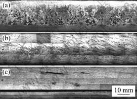
Fig.6 Longitudinal sections under varied welding technology (Rotation speed 1 050 r/min): (a) Transverse speed 140 mm/min; (b) Transverse speed 120 mm/min; (c) Transverse speed 100 mm/min
4 Conclusions
1) It can be concluded through the technical experiment that flow patterns of material at different locations of the weld are varied. Four layers exist obviously along the thickness direction of the welded material: A is the surface flow layer influenced by the shoulder of the tool; B is the horizontally lamellar flow region influenced by the flow of the superficial material; C is the vertically flow region only under the function of the pin; D is the region in which material is unstirred and the force is slight.
2) Due to the varied heat and force of the pin, the flow pattern of material in longitudinal sections at different locations is varied.
3) Welding quantity is significantly influenced by the flow pattern of the welded material and defects are always observed in horizontally lamellar flow region in which the flow pattern is complex.
References
[1] BLAIR L��MURRAY M��WILLIAM B. Material flow in friction stir welding monitored with Al-SiC and Al-W composite markers[A]. Symposium Sponsored by the Shaping and Forming Committee of the Materials Processing & Manufacturing Division of TMS[C]. Indianapolis America, 2003: 3-12.
[2] YING L, MURR LE, McCLURE J C. Solid-state flow visualization in the friction stir welding of 024 Al to 6061 Al[J]. Scripta Materialia, 1999, 40(9): 1041-1046.
[3] YING L, MURR L E, MCCLURE J C. Flow visualization and related microstructures associated with the friction stir welding of 2024 Al to 6061 Al[J]. Materials Science and Engineering A, 1999, 271(1/2): 213-223.
[4] SEIDEL T U, REYNOLDS A P. Visualization of the material flow in AA2195 friction-stir welds using a marker insert technique[J]. Metallurgical and Materials Transactions, 2001, 32A(11): 2879- 2884.
[5] OUYANG J H��KOVACEVIC R. Material flow and microstructure in the friction stir butt welds of the same and dissimilar aluminum alloys[J]. Journal of Materials Engineering and Performance, 2002, 11(1): 51-63.
[6] XU Shao-wen. Microstructure Analysis and Solid Mechanics Modeling of Friction Stir Welding[D]. University of South Carolina, 2003.
[7] COLLLIGAN K. Material flow behavior during friction stir welding of aluminum[J]. Welding Journal, 1999, 78(7): 229-237.
[8] RAFAEL G M. Material Transport During Friction Stir Welding[D]. The University of Texas at el Paso, 2001.
[9] SEIDEL T U. The Development of a Friction Stir Welding Process Model Using Computational Fluid Dynamics[D]. University of Carolina, 2002.
[10] GUERRA M, McCLURE J C, MURR L. Metal flow during friction stir welding[J]. Friction Stir Welding and Processing, 2001, 4(4): 25-34.
[11] GUERRA M, SCHMIDT C, McCLURE J C, MURR L E, NUNES A C. Flow pattern during friction stir welding[J]. Materials Characterization, 2002, 49(2): 95-101.
[12] KRISHNAN K N. On the formation of onion rings in friction stir welds��J��. Materials Science and Engineering, 2002, A327: 246-251.
[13] COLEGROVE P A, SHERCLIFF H R. 3-Dimensional CFD modelling of flow round a threaded friction stir welding tool profile[J]. Journal of Materials Processing Technology, 2005, 169: 320-327.
[14] OUYANG Jia-hu, YARRAPAREDDY E, KOVACEVIC R. Microstructural evolution in the friction stir welded 6061 aluminum alloy (T6-temper condition) to copper[J]. Journal of Materials Processing Technology, 2006, 172(2): 110-122.
[15] WANG Xi-jing, HAN Xiao-hui, LI Chang-feng, BAO Kong. Horizontal flow status of plastic metal in different depth during friction stir welding for thick aluminum alloy[J]. The Chinese Journal of Nonferrous Metals, 2005, 15(2): 198-203. (in Chinese)
(Edited by YANG Bing)
Foundation item: Project(10577010) supported by the National Natural Science Foundation of China
Corresponding author: WANG Xi-jing; Tel: +86-931-2976706; E-mail: wangxj@lut.cn
