
Trans. Nonferrous Met. Soc. China 25(2015) 4089-4101
Discrete element and finite element coupling simulation and experiment of hot granule medium pressure forming
Guo-jiang DONG1, Chang-cai ZHAO2, Yuan-yuan YA2, Jian-pei ZHAO2
1. College of Vehicles and Energy, Yanshan University, Qinhuangdao 066004, China;
2. Key Laboratory of Advanced Forging and Stamping Technology and Science, Ministry of Education, Yanshan University, Qinhuangdao 066004, China
Received 6 January 2015; accepted 21 May 2015
Abstract:
The granule medium of discreteness is supposed to be continuous (Drucker-Prager model) in the existing finite element simulation analysis on the hot granule medium pressure forming (HGMF) process, so the granule medium may produce tensile stress in the process of pressure-transferring and flowing, which does not coincide with the reality. The analysis method, discrete element and finite element (DE-FE) coupling simulation, is proposed to solve the problem. The material parameters of simulation model are obtained by the pressure-transfer performance test of granule medium and the hot uniaxial tensile test of sheet metal. The DE-FE coupling simulation platform is established by adopting Visual Basic language. The features in the process that AA7075-T6 conical parts are formed by the HGMF process are analyzed and verified by the process test. The studies show that the results of DE-FE coupling simulation coincide well with the test results, which provides a new analysis method to solve the mechanics problem in the coupling of discrete and continuum.
Key words:
granule medium; aluminum alloy sheet; hot forming; finite element; discrete element;
1 Introduction
Hot granule medium pressure forming (HGMF) process is used for the hot deep-drawing and bulging on sheet metals and pipes [1-3], in which granule medium replaces the existing soft mould medium in the hot forming process, such as liquids [4], gases [5] and viscous medium. Granule medium has many advantages, such as withstanding high pressure and high temperature, filling well, sealing easily and loading simply. It provides a new method to form the parts formed with light alloy sheet and tube which are difficult to be formed at room temperature [6-8].
As for the study on the HGMF process,  and MERKLEIN [9] used ceramic balls as high- temperature transmission medium to form auto-body parts which were made of high or ultra high strength steel. By this way, the problem that fluid media are normally unstable and easy to leak at high temperature can be solved. Numerical simulation of ceramic balls medium is conducted through the Drucker-Prager material model, and a real cup-shaped part is formed with granule medium [10]. LI et al [11] trial-produced the titanium alloy spinner at about 700 ��C by solid granule medium forming technology. JIN and ZHAN [12] took the composite powder, fine silicon powder and hexagonal boron nitride, as the pressure-transfer medium, and the hot state internal high pressure forming of 40Cr alloy steel pipe fittings was conducted at 500 ��C. The study of existing HGMF process shows that selecting granule medium of different materials can make the process adapt to higher forming temperature environment. Besides, the internal high pressure of forming can be established by using the die with general clearance seal structure without external loading system and the warm or hot-forming on sheet metals or pipes can be realized by general equipment. The important difference among HGMF, thermo- hydroforming (THF) [13] and quick plastic forming (QPF) [14] is the different pressure-transfer media which leads to different forming laws.
The difficulty existing in the mechanics analysis of coupling action of granule medium and sheet metal is that the material properties, mechanical properties and deformation laws of two deformable bodies are all different, so it is the research hot-spot that the method of discrete element-finite element (DE-FE) coupling calculation is used to analyze such problems now. ONATE and ROJEK [15] used finite element and discrete element models to simulate the tool and rock, respectively, and analyzed the fracture of rock and the stress of tool in the process of tunneling. ROJEK et al [16] used the direct coupling approach of two-dimensional granules DE-FE to simulate the process of sand filling cavity. NAKASHIMA and OIDA [17] used DE-FE coupling algorithm to study the stress state of wheel which touches road. Based on the DE-FE node coupling method, GAO and ZANG [18] came up with DE-FE face-center coupling algorithm and DE-FE arbitrariness coupling algorithm which make the size of FE get rid of the limit of size and arrangement of discrete element and realize coupling calculation in different areas of glass plate.
The object of finite element analysis which was used in above method is only limited to the strength problem of elastic deformation. It has not involved the research on discrete body and plastic deformation body coupling deformation process. Meanwhile, the existing commercial software for numerical simulation combining finite element technology dealing with plastic deformation with discrete element technology analyzing granules has not been realized. Based on this, the method of DE-FE coupling simulation was proposed. Finite element method was applied to solving the plastic deformation problems on sheet metal, discrete element method was used to analyze the pressure-transfer laws and flow problems of the granule medium, besides the advantages of discrete element method and finite element method were fully developed through fission calculation, and discrete element was combined with finite element organically through data interaction, thereby the fission coupling simulation platform was established in order to solve the mechanics analysis problems of the coupling deformation of granule medium and plate in HGMF process. The HGMF process test for the parts on AA7075-T6 sheet was conducted to verify the validity of DE-FE coupling simulation method, and the effect of main technological parameters on forming performance of sheet metal was analyzed.
2 Material model of discrete element simulation on granule medium
Based on the requirement of HGMF process, metallic granules (MG) and non-metallic granules (NMG), whose diameters are in the range of 0.08-0.32 mm and the shape is near-spherical, were chosen as the medium (as shown in Fig. 1). Finally, the NMG was selected as the pressure-transfer medium for hot deep-drawing forming on the aluminum alloy sheet. The main ingredients of NMG medium are 68% ZrO2 and 32% SiO2, the Rockwell hardness of NMG reaches HRC 48-55 and the appearance of NMG is round and smooth, so, the NMG medium belongs to the non-cohesive material, namely, its cohesion is zero. The material composition of NMG makes it able to maintain stable mechanical and chemical properties at moderate temperatures (350 ��C), which shows that the NMG can keep a certain degree of hardness and has no cohesive phenomenon at high pressure.
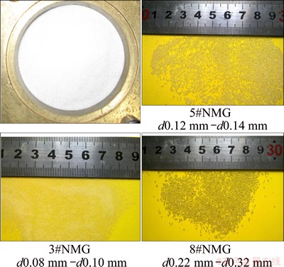
Fig. 1 Pictures of NMG
The research on mechanics of solid granules is traditionally based on the assumption of continuous medium, namely, the research object is made of a large number of micelles without clearance [19]. However, granular material has dispersive characteristics, such as the physical property, shape and particle size, and mechanical properties, such as the transient state, fluctuation, collision, and crush in the process of movement. These characteristics are in conflict with the assumption of uniform and continuous characteristics obtained by macroscopic continuous mechanics theory, so, the reality is different from the theory.
The discrete element method regards the whole medium as a series of granules of independent movement. Using rigid system hypothesis and Newton��s second law, the forces (collision force and field force) of each granule in the system were studied through the contacted constitutive relation among granules in order to describe the particle system. The simulation of isotropic compression and shearing was proceeded on sphere and ellipsoid granules cluster by using PFC-2D/3D discrete element procedure reported in Refs. [20,21]. The change rule of granular microstructure was analyzed and the results are very close to the results of test.
The discrete element procedure PFC-2D/3D adopt the granular flow method to simulate the movement and interaction of circular granule medium. The basic assumptions are as follows:
1) Granular cell is the rigid body and the damage of granules is ignored.
2) The contact among granules happens in a small range, namely point contact.
3) The characteristic of contact is flexible, a certain amount of ��overlap�� can occur in contact place, and its size is related to the contact force.
4) Granular cell is regarded as circle in 2D and sphere in 3D.
The parameters of granular material in PFC-2D software were confirmed by uniaxial compression test. Through the mutual authentication of physical experiment and numerical simulation, the macroscopic mechanical parameters of physical model and mesoscopic structure parameters of granule medium were corresponded in order to obtain the mesoscopic parameters which were suitable for granular materials. Therefore, in the first place, the uniaxial compression tests of solid granules were conducted and the discrete element numerical model under the same conditions was established, the mesoscopic parameters were adjusted to make the simulation data coincide with the measured data. Then, the validity and reliability of setting parameters were ensured by the pressure-transfer performance test contrasting and verifying.
The relation curve between axial strain ��1 and principal stress ��1 of 5#NMG medium was obtained by uniaxial compression test [2] and the experiment process was analyzed by the PFC-2D software. The numerical model of granule clusters was made of spherical granules of different diameters, the diameters were 0.117, 0.125 and 0.140 mm, respectively, and the scale was 1:2:1. The linear contact model was used in the discrete element simulation. In the simulation process, the granule clusters started to pile up under the effect of gravity. Then, the indenter was down to compress the granules. Finally, the granules formed a dendritic contact force chain structure. The results of discrete element numerical simulation and the measured values are basically coincident, as shown in Fig. 2. Therefore, the discrete element microstructure parameters of 5#NMG medium are obtained, as shown in Table 1.
For further verifying the applicability of the discrete element simulation parameters in Table 1, the pressure- transfer performance test of granule medium was conducted, as shown in Fig. 3. For experimental setups, twelve sensors for measuring the radial pressure PR were designed in different locations of cylinder wall along the Z-axis direction, and twelve sensors for measuring the axial pressure PZ were installed in different radius locations at the bottom of cylinder along the R-axis direction. In the experiment, the charging barrel was filled with a certain volume of NMG, the pressure P was loaded on indenter and the signals of pressure and displacement were collected synchronously.
According to the above conditions of the pressure- transfer performance test, the discrete element numerical simulation model of pressure-transfer performance test was established.
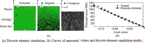
Fig. 2 Uniaxial compression test analyzed by discrete element simulation
Table 1 Discrete element simulation parameters of 5#NMG
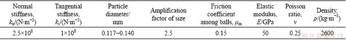
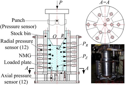
Fig. 3 Principle of solid granule medium pressure-transfer performance test
1) Establishing the border conditions. The boundary wall was established according to the actual working conditions of the pressure-transfer performance test to express the entity components such as pressure head, pressure cylinder and pressure drum.
2) Creating 5#NMG medium granule clusters. The sample of granule clusters made of 28800 granules was created according to the layering underpressure approach in the closed area. The sample of granule clusters was made of spherical granules with different diameters, the diameters were 0.117, 0.125 and 0.140 mm, respectively, and the scale was 1:2:1.
3) Loading condition. The axial load was applied to indenter until the specified pressure value of the granule clusters.
The material parameters of 5#NMG are given in Table 1, the simulation process is shown in Fig. 4. Granules are generated using the method of the layering underpressure approach and the granules contact fully. The force-chain networks constantly change with increasing the pressure, and the ramous force-chain network formed by contact force gradually extends from the pressure head boundary into the far distance with appearing attenuating property. When the load is completed, the contact force-chains among granules are stubby and strong mostly, and the basic structure of force-chain network changes from circle to oval.
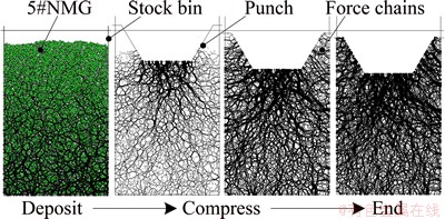
Fig. 4 Force-chain networks of granule medium at different compressing stages
The data curves of pressure-transfer performance collected by PFC-2D simulation software are compared with the measured curves, as shown in Fig. 5. It is observed that the distributions of radial and axial pressures obtained by the discrete element simulation of 5#NMG medium pressure-transfer are basically consistent with the change rule of measured values, but the pressures are a little higher than the measured values as a whole. Besides, the radial pressure decreases progressively from the pressure head area to the bottom while the axial pressure decreases progressively from the center to outward.
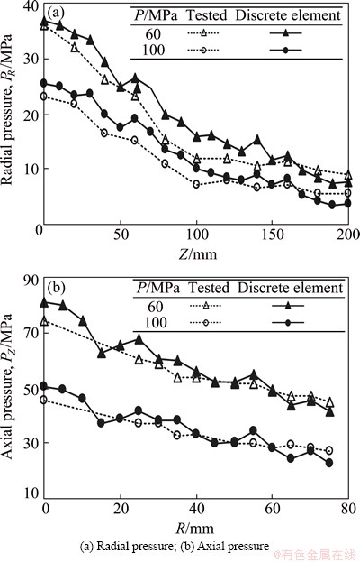
Fig. 5 Comparison between measured pressure curves of 5#NMG and results of discrete element method simulation
Through the pressure-transfer performance test, it is concluded that the pressure distribution of pressure- transfer of 5#NMG in radial and axial directions is non-uniform. Using the parameters in Table 1 to conduct the discrete element simulation, the rules of pressure- transfer of NGM medium can be more accurately reflected, and the parameters can be applied to the HGMF process simulation analysis.
3 Material model of finite element simulation on sheet metal
The experimental material is AA7075-T6 super- strength aluminum alloy cold-rolling sheet which was produced in Southwest Aluminum (Group) Co. Ltd and the specification of sheet metal is 1.0 mm �� 1200 mm �� 2000 mm. The constitutive relation curves and the material performance parameters, such as the thickness anisotropy coefficient, were measured by hot uniaxial tensile test. The true stress-strain curves of AA7075 sheet under the conditions of different strain rates  and temperatures t were obtained by experiments, as shown in Fig. 6. Using the dynamic response mathematical model of single-increasing function, multiple linear regression statistics of the test data were conducted, and finally, the constitutive equation was obtained, namely,
 (1)
(1)
where  is the equivalent stress,
  is the equivalent strain,
  is the equivalent strain rate, t is the deformation temperature.
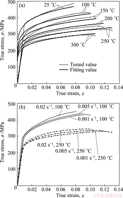
Fig. 6 True stress-strain curves of AA7075 sheet at strain rate of 0.001 s-1 and different temperatures (a) and at different strain rates and temperatures of 100 ��C and 250 ��C (b)
The elongations (Agt) at the maximum force of AA7075-T6 sheet are all less than 12.5% from room temperature to 300 ��C, as shown in Fig. 7, and the samples do not produce necking phenomena before the deformation is less than 8%. So, the strain data were collected to obtain the thickness anisotropy coefficient (r-value) when the strain rate is 0.001 s-1 and the engineering strain is 7%, as shown in Fig. 8. The weighted average plastic strain ratio  can be accurately fitted by the linear equation:
 (2)
(2)
The curve of the directivity coefficients ��r changing with the temperature of AA7075-T6 sheet can be obtained, as shown in Fig. 9. The ��r-values are all less than zero from room temperature to 300 ��C, the absolute value of ��r reaches the maximum at 200 ��C, and then quickly reduces.
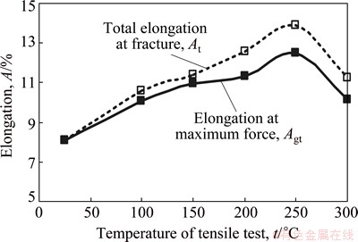
Fig. 7 Elongation curves of AA7075-T6 sheet at different temperatures and strain rates
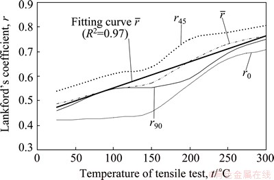
Fig. 8 Lankford��s coefficient curves of AA7075-T6 sheet at strain rate of 0.001 s-1
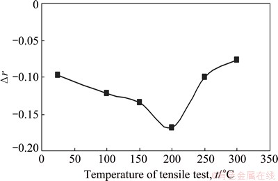
Fig. 9 Directivity coefficient curves of AA7075-T6 sheet
For the AA7075-T6 sheet, the r-value is larger at 250-300 ��C while the absolute value of ��r is smaller, namely, the thickness anisotropy characteristics are more obvious while the in-plane anisotropy characteristics are comparatively less obvious. At the same time, according to the changing rule of elongation at different temperatures and the fact that the value of elongation reaches the maximum at 250 ��C, it can be speculated that the best forming temperature of AA7075-T6 sheet is at about 250 ��C. So, the temperatures of HGMF process numerical simulation focus on the range of 200-300 ��C.
NAKA et al [22] showed that Hill-48 yield criterion does not match the sheet materials with r<1, but Hill-48 yield criterion can more accurately describe the yield characteristics of aluminum alloy sheet when the r-value approaches 1 at high temperatures [23]. Based on the data of the hot uniaxial tensile test, the yield loci of Hill-48 and Logan-Hosford are shown in Fig. 10, the maximum difference occurs in the place of bidirectional tensile or compress stress, but this characteristic weakens significantly with the increase of temperature, the maximum difference of the two yield loci is less than 4.4%-6.5% when the temperature reaches 200-300 ��C.
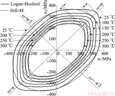
Fig. 10 Yield loci of AA7075-T6 sheet changing with forming temperatures
According to the constitutive equation, the thickness anisotropy coefficient, the Hill-48 yield equation and the yield strength curve, which are associated with the deformation temperature, the forming limit diagram (FLD) of AA7075-T6 sheet being related to temperature can be derived using the Hill��s localized instability theory and the Morciniak-Kuczyski (M-K) method [23], as shown in Fig. 11.
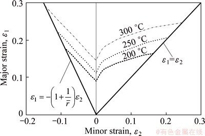
Fig. 11 Theoretical predictions of FLD at strain rate of 0.001 s-1
The finite element simulation model of sheet metal forming was established by software ABAQUS, in which the constitutive relation, the yield criterion and the fracture instability criterion were set by the test.
4 DE-FE coupling simulation
AA7075 conical parts formed by the HGMF process are taken for an example to establish the model of DE-FE coupling simulation and simulate the forming process. The principle of HGMF process is shown in Fig. 12. The mould devices are mainly made up of indenter, die, blank holder, the device for adjusting blank holder gap (BHG), and temperature-controlling system. In Fig. 12, t0 is the initial thickness of plate, D0 is the initial diameter of blank, RD is the round corner of die entrance. The forming height and the shape of the bottom don��t limit size, only H is defined as the height of free forming of parts.
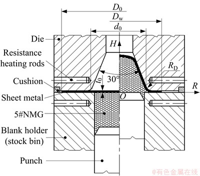
Fig. 12 Schematic diagram of HGMF process
The process of forming test is as follows. Firstly, according to the requirements of process, the molds were closed and heated after packing a certain volume of granule medium and setting the BHG. Secondly, the molds were opened when the temperature reached the setting one, and the plate coated with lubricant was put on the blank-holder, then, the molds were closed and heated to the setting temperature. Finally, the punch was loaded by the inner slide, and at the same time, the real-time signals of pressure and displacement were collected.
4.1 Platform of DE-FE coupling simulation
The idea of DE-FE coupling simulation analysis is to make continuous forming process discrete. The discrete element method is used to analyze the pressure-transfer law of granule medium, the finite element method is used to analyze the deformation characteristics of sheet metal, and the data are transmitted and converted by the simulation platform compiled with Visual Basic language to realize the DE-FE coupling simulation. The technology roadmap is shown in Fig. 13.
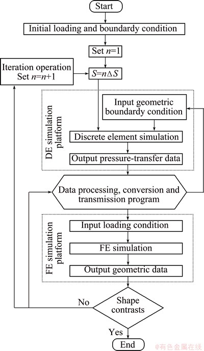
Fig. 13 Technology roadmap of DE-FE coupling simulation platform
1) Discrete element simulation model of the pressure-transfer performance analysis was established. Based on discrete element software PFC-2D platform, the mesoscopic parameters of discrete element simulation analysis on 5#NMG were set. The simulation environments such as the boundary of DE model, particles cluster, loading method were established according to the actual conditions, as shown in Fig. 14.
The geometry of deformation plate walls was obtained by the finite element simulation analysis, the coordinate values of deformation plate unit were outputted and turned into rigid boundary condition in the discrete element model. The number and shape of rigid body border in the discrete element model depend on the number and deformation conditions of plate unit in the finite element simulation, which realizes the conversion through the finite element simulation output and discrete element model boundary input.
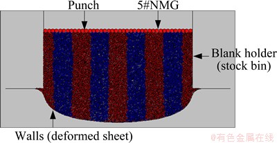
Fig. 14 Discrete element simulation model
2) Finite element simulation model on plate deformation analysis was established. The finite element simulation model of plate was established using ABAQUS/Explicit nonlinear dynamic analysis method. The test of AA7075-T6 sheet material performance shows that the absolute values of ��r, which are plane directivity coefficients of sheet metal, are all less than 0.17 from room temperature to 300 ��C. This means that the characteristics of plane anisotropy are not obvious. Meanwhile, the cylindrical part is axially symmetric and revolving, and granule medium is analyzed by PFC-2D discrete element model, which has the characteristic of axial symmetry. Therefore, the axisymmetric model for analysis was established in order to reduce the computational cost.
Besides, the die, solid granule medium and sheet metal were all heated to an objective forming temperature, and the temperature should be maintained constant during the loading. So, if the function switching effect is ignored in the forming process, the forming can be considered as isothermal deep-drawing, namely the heat exchanging effect among the die, medium and sheet metal in the process of numerical simulation is overlooked. The die and blank holder are regarded as the rigid bodies and the axisymmetric analytical rigid body model is established in accordance with the geometries of actual conditions. The die is regarded as the rigid bodies, so contact pair algorithm, offered by ABAQUS/Explicit, is selected to deal with the contact problems between the mold and sheet metal. Coulomb friction coefficient is supposed as 0.08. The sheet metal adopted the 2-node linear axisymmetric shell elements SAX1 and seven integrated points are set along the thickness direction.
The contact pressure between granule medium and sheet metal is obtained by discrete element simulation, and the loading is imposed using the surface traction model in load function module of ABAQUS. This model can apply unit area loading on the surface of solid or cell, the loading can be the shearing force or the force at any direction, and the direction of the force can be described through a vector. The loading value of sheet metal through the surface traction model depends on the value of discrete element simulation. The simulation model of finite element is shown in Fig. 15.
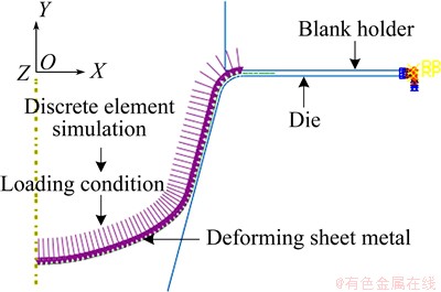
Fig. 15 Finite element simulation model
3) DE-FE coupling simulation platform was established. The programs of granule medium loading and pressure-transfer data collecting were developed by applying the control function of background program of PFC-2D. The program of collecting data on loading inputting and deformation was developed by applying the ABAQUS secondary development platform and data transmission interface. The program module of interactively transmitting data was developed by VB software platform in order to realize the coupling simulation function of DE-FE fission operation and data transmission.
The solving process of DE-FE coupling simulation is as follows. Firstly, the analysis step was set as n=1, the initial load of discrete element model of granule medium was supposed as S=n��S and the boundary conditions were set as the initial geometry of sheet metal. Then, the data of contact pressure between granule medium and the boundary of plate were solved and output by discrete element platform, meanwhile the boundary of plate was undeformed rigid boundary. Because the supposed initial load reduction ��S was smaller, the effect of small deformation of plate on contact pressure between the plate and granule medium can be ignored. The contact pressure datum were converted into load data format of sheet metal forming and transmitted to finite element platform, at this moment the sheet metal had not been deformed. The data of geometry, thickness distribution, stress field and strain field in the deforming process of sheet metal were solved and collected by the finite element platform. The data of geometry in the deforming process of sheet metal were output and analyzed by comparing with the objective shape of product. If the deformation shape reached the forming target, the analysis was stopped. If not, the data of geometry would be converted to the rigid boundary conditions of contact between granule medium and sheet metal in the next analysis step, which were input into the discrete element simulation platform. Setting analysis step n=n+1 and superimposing pressing amount S=n��S, the analysis proceeded. Meanwhile, the data of geometry, thickness distribution, stress field and strain field in the deforming process of sheet metal, which were solved by finite element, were output and converted into the initial boundary condition in the next analysis step in order to continue loading and solving, as shown in Fig. 13.
The factors that affect the accuracy of DE-FE coupling simulation are as follows: 1) the number of analysis steps, namely the value of n; 2) the number of units partitioned on plate which is not only connected with the accuracy of solving plastic deformation and stress state of plate by the finite element model but also connected with the degree of the discrepancy between the rigid boundary of plate and the actual deforming shape of plate in the discrete element model. However, the above two factors are also limited by the cost of simulation analysis. Therefore, the calculating accuracy and calculating cost must be taken into account comprehensively in practical application.
4.2 DE-FE coupling simulation analysis
The simulation of HGMF process on conical parts is taken for an example to verify the feasibility of DE-FE coupling simulation model and detect the characteristics of HGMF process. The conical parts were designed with the diameter of die d0=80 mm, the die fillet RD=5 mm, and the half-cone angle (an angle between generatrix and axis) of 15��, which belong to deep taper, as shown in Fig. 12. The AA7075-T6 sheet, with the initial thickness ��0=1.0 mm, was adopted.
The initial diameter (D0) of blank was assumed to be 125 mm. Then, the control method of setting BHG was adopted, namely, the BHG remained unchanged in the process of deep-drawing. The BHG was set as ��g=1.15��0, based on the above conditions, three samples, whose forming temperatures are 200, 250 and 300 ��C respectively, were determined and calculated by numerical simulation. When the forming height (H) is 40 mm at the above forming temperatures, the major strain ��1 values (the axial strain ��R) and the minor strain ��2 values (the hoop strain ����), which are distributed along the generatrix of parts, were collected and drawn in the theoretical FLD, as shown in Fig. 16.
Figure 16 shows that the effect of the forming temperature on the locus of principal strain in the forming process of sheet metal is not obvious, the loci of principal strain basically coincide. Within this range, point B close to the uniaxial tensile state is the closest to the fracturing limit, namely, the value of principal strain in this area exceeds the forming limit curve (FLC) at 200 ��C. But the principal strain loci of analyzed samples at 250 and 300 ��C are still in the safe area.
The effect of increasing the forming temperature on the principal strain locus of the tension-compression area AC of part is not obvious. But the range of theoretical forming limit is expanded with increasing the forming temperature, so the area AC of part formed at high temperature tends to be safe, which means that the fracturing trend can be suppressed with increasing the forming temperature.
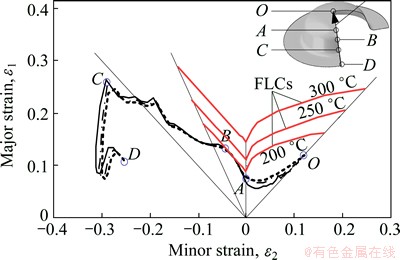
Fig. 16 Principal strain loci at different forming temperatures (D0=125 mm, ��g=1.15��0)
Supposing t=250 ��C, ��g=1.15��0 and D0=130 mm, the simulation data curves of conical parts in different forming stages were obtained using the analysis method of DE-FE coupling simulation, as shown in Fig. 17.  is used to express a series of feature-points of conical part in the forming process. For example, the feature-points moving from
  to
to  means that the forming height H changes from 30 to 50 mm.
The results of DE-FE analysis show that, as shown in Fig. 17, in the mid-early stage of forming conical parts (H=30 mm), the reduction of wall-thickness is smaller and the thinnest point appears at the center of bottom and point  in the middle of cone wall. In the late stage of forming process, the free deforming area at bottom thins down most seriously, and the flange area thickens obviously. The principal strain loci in different stages of forming process are expressed in Fig. 17(c). In the mid-early stage of forming process, points
  and , which are the nearest points to the fracturing limit curve, are two peaks on the principal strain locus, and they are located at the transitional junction of the bottom fillet and the middle of cone wall, respectively. Finally, the two points become the most dangerous area to fracture in the middle of forming process. With the development of deformation, the materials at points and flow to points
  and
and  , respectively, whose locations on principal strain locus are still the points in danger of fracture in the tension-compression state. Meanwhile, the free deforming area at bottom thins down sharply, the locus between points
  and
and  exceeds the fracturing limit and becomes the most dangerous area in the late stage of forming process. The effect of BHG on the forming performance of conical parts can be analyzed through assuming that t=250 ��C and D0=130 mm. Based on the above conditions, the controlling method of BHG was adopted, and the BHG was set as 1.10��0, 1.15��0 and 1.20��0, respectively. When the forming height H is 45 mm under different BHGs, the principal strain locus, which is distributed along the generatrix of parts, was collected, as shown in Fig. 18.
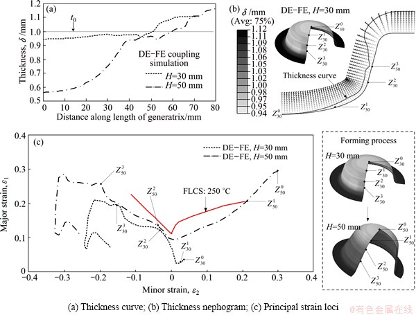
Fig. 17 Comparison of simulation data of conical parts
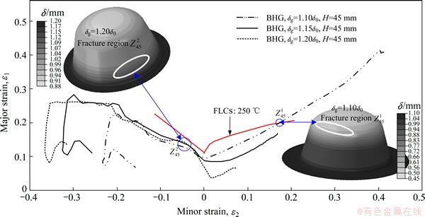
Fig. 18 Principal strain loci of conical parts under different BHGs
Figure 18 shows that, if the BHG is too small, the deforming resistance of sheet metal around the flange will increase, which results in that the free deforming area at bottom thins down sharply and the area from point  to the bottom center has risk to fracture. If the BHG is too large, the points in danger of fracture will occur in the middle of circular cone. Near point
  in Fig. 18, it can be seen that the principal strain locus with larger BHG is closer to the fracturing limit curve. The reason is that the bending stress of sheet metal flowing into the die increases with the excessive thickening of flange, thus, the deep-drawing deforming resistance increases, which results in the increase of radial stress. As a result, point flows to the fracturing limit curve. Therefore, under the condition of adopting the controlling method of BHG, the BHG is too large or too small, which may lead to the fracturing risk of parts. Particularly, in the actual production, overlarge BHG can make flange slightly wrinkle, which may further increase the frictional resistance between the blank and mold to increase the fracturing risk. Meanwhile, the slight wrinkling may form wrinkle marks on the surface of parts to influence the surface quality of parts.
Considering the results of DE-FE coupling simulation analysis, for the AA7075-T6 conical parts (the bottom is free bulging area), the initial diameter of blank D0=125-130 mm, the forming temperature t>250 ��C, the BHG ��g=1.15��0-1.20��0. The conical parts, with the height of parts being about 45 mm and the wall-thickness-difference of parts being less than 0.33 mm, are obtained using the HGMF process, and the forming force is less than 110 kN.
5 HGMF process test
In the test, the AA7075-T6 sheet, whose diameter is 125 mm, was adopted, the BHG was set to be ��g=1.15��0=1.15 mm and the range of forming temperature was 25-270 ��C. The conical parts close to the forming limit were obtained by the test under different forming temperatures, as shown in Fig. 19. When the forming temperatures are below 230 ��C, the formability of sheet metal is poor. The analysis on the macroscopic fracture morphology shows that the fracturing surfaces all occur at lower location of die fillet entrance at 200 ��C, which present the observable characteristics of brittle fracture. There exist no obvious tearing ridges, and the small fracturing dimples are shallow. At 200-230 ��C, the fracturing surfaces almost occur at the transitional junction of the bottom fillet and the middle of cone wall, which develop along the circumferential direction of parts, and the characteristics of ductile fracture occur in the place of fracture. The river patterns in the place of fracture are significant, which can also be seen in the larger dimples. The smaller dimples are deeper, and there exist obvious tearing ridges. The trends and positions of fracture are consistent with the results of DE-FE coupling simulation analysis, as shown in Fig. 16.
When the forming temperature reaches 250 ��C, the formability of sheet metal was significantly improved which was very stable, and the relative height (H/d0) of conical parts with half cone angle of 15�� formed in one step H/d0=0.57 (H=45.5 mm). The quality of the interior and exterior surfaces of parts is good. The maximum wall-thickness difference is less than 0.4 mm, and the thinnest wall-thickness, which occurs at the bottom center of free deforming area, is 0.72 mm. The above contents are consistent with the results of DE-FE coupling simulation analysis.
When the forming temperature reaches 270 ��C, the relative height of parts formed in one step H/d0=0.59, but the stability of sheet metal forming declines, and the yield is low. This is related to the property that AA7075-T6 is a typical heat-treatable material. Further increase of forming temperature affects the state of heat-treatment, which results in that the elongation of AA7075-T6 sheet produces downward trend to affect the forming properties. The process test shows that the optimal deep-drawing forming temperature of AA7075-T6 sheet is 250 ��C.
In the test t=250 ��C and D0=125 mm, the effect of BHG on the forming performance was studied with different BHGs. A lot of tests show that the BHG is too large or too small, which easily makes the sheet metal fracture in the forming process, while the appropriate BHG makes the quality of deep-drawing parts more stable without fracture, as shown in Fig. 20. When BHG is smaller (��g=1.10��0), the fractures of parts occur at the late stage of forming process, the location of fracture surface is in the bi-tension area at the bottom of part. The wall-thickness at bottom thins seriously and the thickness of fracture is only 0.64 mm, the ratio of the outer diameter of flange to the initial diameter of sheet metal (Dw/D0) is 0.912. If the BHG is too small, the deforming resistance around the flange area increases. The sheet metal in the flange area is difficult to satisfy the needs of deep-drawing, the forming of parts mostly relies on the thinning of sheet metal at bottom, so serious thinning occurs at the bottom of sheet metal. The deep-drawing force increases with the development of forming. When the carrying capacity of a circular section in free deforming area reaches the limit, the fracture instability occurs. When ��g=1.20��0, the fracture occurs at the medium stage of forming process. The fracture surface locates in the middle of conical filming area, and the thickness of fracture is 0.84 mm. The larger BHG makes sheet metal flow smoothly at the beginning of deep-drawing forming process, and the load-bearing of sheet metal at the bottom and the reduction of wall-thickness are small. But larger BHG makes flange area wrinkle slightly, which flows into the filming area at the middle stage of forming process, so that the friction between the sheet metal and the die or the blank-holder is enhanced rapidly, which prevents the plate from deforming and flowing, so the forming force increases rapidly, and the fracture occurs instability. At this time, Dw/D0=0.848, the wrinkling is the most serious in theory. The mechanism that the change of BHG leads to fracture instability, obtained by experiments is consistent with the trend predicted in the DE-FE coupling simulation, as shown in Fig. 18.
The conical parts produced by process test were cut and measured, and the contour of generatrix and the distribution curve of wall-thickness were obtained and compared with the results of DE-FE coupling numerical simulation, as shown in Figs. 20(a) and (b). The contrast shows that the contour of generatrix obtained by finite element numerical simulation is consistent with that obtained by the test, and the free deforming area at the bottom of conical parts is approximately spherical crown. The wall-thickness curve of part measured by the test is also very close to the result of simulation, the maximum deviation occurs at the center of bottom, and the simulation value is less than the measured wall-thickness value by 5.5%.
Through repeated verification and contrast between a lot of technological tests and numerical simulation, the results show that the DE-FE coupling simulation model is more suitable for simulating the HGMF process on the aluminum alloy sheet. The mechanical parameters of granule medium and the deforming rules in the coupling deformation process are reflected accurately. The bottleneck of computing efficiency in the DE-FE coupling simulation model is that the computing cost of discrete element simulation on granule medium is higher. But for solving the forming problem of non- axisymmetric sheet or tube components with complex sections, the results deviate from the actual condition based on the continuity hypothesis of granule medium in the finite element numerical model. At the same time, the complex deformation of granule medium can make finite element mesh produce large distortion in the calculation, which leads to the reduction of the analytical precision greatly, even the calculation is difficult to proceed. The above problems can be solved effectively using the DE-FE coupling simulation analysis method.
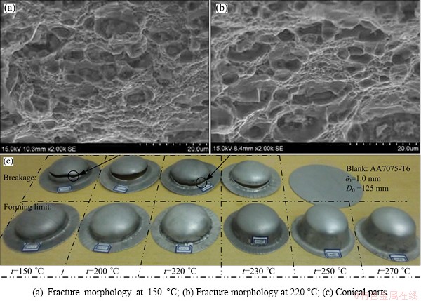
Fig. 19 Conical parts obtained in test at different temperatures (D0=125 mm, ��g=1.15��0)
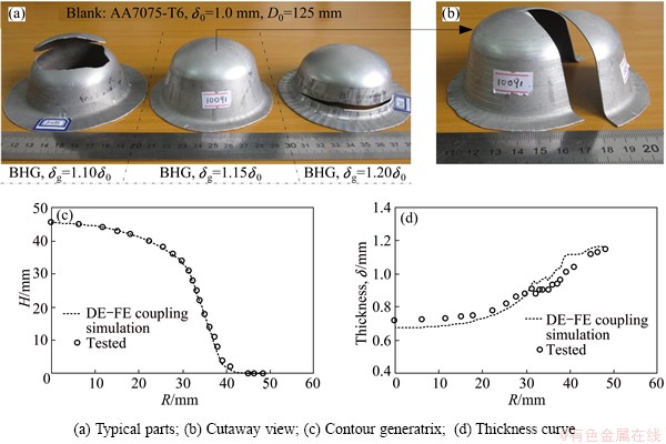
Fig. 20 Typical parts obtained in test under different BHGs (t=250 ��C)
6 Conclusions
1) The material performance parameters of AA7075-T6 sheet at 25-300 ��C, such as constitutive relation, elongation and thickness anisotropy coefficient, are all obviously sensitive to the temperature. The combination property shows that the formability of AA7075-T6 sheet at 250 ��C is optimal.
2) The DE-FE coupling simulation model of HGMF process is established. The simulation analysis shows that the effect of increasing the forming temperature on the principal strain locus of deforming part is not obvious. But the range of theoretical forming limit is expanded with increasing the forming temperature, thus, the formability is improved. The oversize or undersize BHG may all result in the part fracture, and the fracture areas are different, which are the middle of cone and the free forming area at the bottom, respectively.
3) The process test shows that the results, such as the shape of part and the distribution of thickness, obtained by the DE-FE coupling simulation analysis method are consistent with the test. The combination of DE-FE coupling simulation and the theoretical FLD of AA7075-T6 sheet established based on the hot uniaxial tensile test can accurately predict the fracture instability phenomenon in the forming process.
4) When the forming temperature reaches 250 ��C, the AA7075-T6 conical parts with half cone angle of 15�� and relative height (H/d0) of 0.57 can be formed in one step.
References
[1] CAO Miao-yan, ZHAO Chang-cai, WU Li-jun, DONG Guo-jiang. Lubricant research on SGMF of magnesium alloy sheet [J]. Advanced Materials Research, 2013, 675: 311-316.
[2] DONG Guo-jiang, ZHAO Chang-cai, CAO Miao-yan. Flexible-die forming process with solid granule medium on sheet metal [J]. Transactions of Nonferrous Metals Society of China, 2013, 23(9): 2666-2677.
[3] DONG Guo-jiang, ZHAO Chang-cai, CAO Miao-yan. Process of back pressure deep drawing with solid granule medium on sheet metal [J]. Journal of Central South University, 2014, 21(7): 2617-2626.
[4] POURBOGHRAT F, VENKATESAN S, CARSLEY J E. LDR and hydroforming limit for deep drawing of AA5754 aluminum sheet [J]. Journal of Manufacturing Processes, 2013, 15(4): 600-615.
[5] LIU Yi, WU Xin. An EBSD study on the texture evolution in coarse-grained AZ31 magnesium alloy by tensile deformation at high temperatures [J]. Metallurgical and Materials Transactions A: Physical Metallurgy and Materials Science, 2006, 37(1): 7-17.
[6] KUMAR M, SOTIROV N, CHIMANI C M. Investigations on warm forming of AW-7020-T6 alloy sheet [J]. Journal of Materials Processing Technology, 2014, 214(8): 1769-1776.
[7] DU Bing, ZHAO Chang-cai, LIU Yi-jiang, DONG Guo-jiang. Research on different patterns of tube bulging process [J]. Journal of Mechanical Engineering, 2013, 49(7): 148-156. (in Chinese)
[8] DU Bing, ZHAO Chang-cai, LI Xue-feng, HE Xin, DONG Guo-jiang. Forming technology of high temperature alloy convex ring shaped tube by solid granule medium [J]. The Chinese Journal of Nonferrous Metals, 2014, 24(7): 1721-1729. (in Chinese)
[9] M, MERKLEIN M. Consideration of elastic tool deformation in numerical simulation of hydroforming with granular material used as a medium [J]. Key Engineering Materials, 2011, 473: 707-714.
[10] M, MERKLEIN M. Numerical simulation of hydro forming at elevated temperatures with granular material used as medium compared to the real part geometry [J]. International Journal of Material Forming, 2010, 3(1): 279-282.
[11] LI Peng-liang, ZHANG Zhi, ZENG Yuan-song. Study on titanium alloy spinner based on solid granules medium forming [J]. Forging and Stamping Technology, 2012, 37(5): 60-63. (in Chinese)
[12] JIN Cheng-zhu, ZHAN Ge. Research on properties of powder pressure transmission mediumin hot state internal high pressure forming [J]. China Mechanical Engineering, 2012, 23(15): 1864-1867. (in Chinese)
[13] PALUMBO G, PICCININNI A. Numerical-experimental investigations on the manufacturing of an aluminium bipolar plate for proton exchange membrane fuel cells by warm hydroforming [J]. International Journal of Advanced Manufacturing Technology, 2013, 69(1-4): 731-742.
[14] LIANG Hai-jian, WU Xiao-wei, WANG Yong, JIN Quan-lin, MA Zhao-li, FENG Shuang-sheng. Research on quick superplastic forming for aluminium alloy sheet [J]. Materials Science Forum, 2013, 735: 301-306.
[15] ONATE E, ROJEK J. Combination of discrete element and finite element methods for dynamic analysis of geomechanics problems [J]. Computer Methods in Applied Mechanics and Engineering, 2004, 193(27-29): 3087-3128.
[16] ROJEK J, ZARATE F, de SARACIBAR C A, GILBOURNE C, VERDOT P. Discrete element modelling and simulation of sand mould manufacture for the lost foam process [J]. International Journal for Numerical Methods in Engineering, 2005, 62(11): 1421-1441.
[17] NAKASHIMA H, OIDA A. Algorithm and implementation of soil-tire contact analysis code based on dynamic FE-DE method [J]. Journal of Terramechanics, 2004, 41(2-3): 127-137.
[18] GAO Wei, ZANG Meng-yan. Simulation of impact fracture process of laminate glass beam based on cohesive model [J]. Journal of South China University of Technology (Natural Science Edition), 2013, 41(5): 139-144. (in Chinese)
[19] YAO Yang-ping, ZHANG Bing-yin, ZHU Jun-gao. Behaviors, constitutive models and numerical simulation of soils [J]. China Civil Engineering Journal, 2012, 45(3): 127-150. (in Chinese)
[20] NING Z, GHADIRI M. Distinct element analysis of attrition of granular solids under shear deformation [J]. Chemical Engineering Science, 2006, 61(18): 5991-6001.
[21] JIANG M J, YAN H B��ZHU H H, UTILI S. Modeling shear behavior and strain localization in cemented sands by two-dimensional distinct element method analyses [J]. Computers and Geotechnics, 2011, 38(1): 14-29.
[22] NAKA T, NAKAYAMA Y, UEMORI T, HINO R, YOSHIDA F. Effects of temperature on yield locus for 5083 aluminum alloy sheet [J]. Journal of Materials Processing Technology, 2003, 140(1-3): 494-499.
[23] CHU X R, LEOTOING L, GUINES D, RAGNEAU E. Temperature and strain rate influence on AA5086 forming limit curves: Experimental results and discussion on the validity of the M-K model [J]. International Journal of Mechanical Sciences, 2014, 78: 27-34.
�ȿ�������ѹ�����ι�����ɢԪ������Ԫ��Ϸ�����ʵ��
������1���Գ���2��Ѻ����2���Խ���2
1. ��ɽ��ѧ ��������ԴѧԺ���ػʵ� 066004��
2. ��ɽ��ѧ �Ƚ���ѹ���μ������ѧ�������ص�ʵ���ң��ػʵ� 066004
ժ Ҫ����������̬��������ѹ������(HGMF)��������Ԫ��������У���Ҫ������ɢ���ʵĿ�������Ϊ������(Drucker-Pragerģ��)����ʹ�ÿ��������ڴ�ѹ�����������в�����Ӧ������ʵ�ʹ��ղ������Ϊ��������⣬�����ɢԪ������Ԫ(DE-FE)��Ϸ������������ͨ���������ʴ�ѹ����ʵ��Ͱ���ȵ�������ʵ��õ�����ģ�͵IJ��ϲ���������Visual Basic���Խ���DE-FE��Ϸ���ƽ̨������HGMF���ճ���AA7075-T6Բ�μ��Ĺ��������������й���������֤���о�����: DE-FE��Ϸ�������ʵ�����ǺϽϺã�Ϊ�����ɢ����������������õ���ѧ�����ṩ�µķ����ֶΡ�
�ؼ��ʣ��������ʣ����Ͻ��ģ��ȳ��Σ�����Ԫ����ɢԪ
(Edited by Mu-lan QIN)
Foundation item: Projects (51305386, 51305385) supported by the National Natural Science Foundation of China; Project (E2013203093) supported by the Natural Science Foundation of Hebei Province, China
Corresponding author: Chang-cai ZHAO; E-mail: zhao1964@ysu.edu.cn
DOI: 10.1016/S1003-6326(15)64060-2
Abstract: The granule medium of discreteness is supposed to be continuous (Drucker-Prager model) in the existing finite element simulation analysis on the hot granule medium pressure forming (HGMF) process, so the granule medium may produce tensile stress in the process of pressure-transferring and flowing, which does not coincide with the reality. The analysis method, discrete element and finite element (DE-FE) coupling simulation, is proposed to solve the problem. The material parameters of simulation model are obtained by the pressure-transfer performance test of granule medium and the hot uniaxial tensile test of sheet metal. The DE-FE coupling simulation platform is established by adopting Visual Basic language. The features in the process that AA7075-T6 conical parts are formed by the HGMF process are analyzed and verified by the process test. The studies show that the results of DE-FE coupling simulation coincide well with the test results, which provides a new analysis method to solve the mechanics problem in the coupling of discrete and continuum.
