

J. Cent. South Univ. (2018) 25: 2258-2271
DOI: https://doi.org/10.1007/s11771-018-3911-8

Superposed disturbance mechanism of sequential overlying strata collapse for gob-side entry retaining and corresponding control strategies
HAN Chang-liang(������)1, ZHANG Nong(��ũ)1, RAN Zhi(Ƚ��)1, GAO Rui(����)2, YANG Hou-qiang(���ǿ)1
1. School of Mines, Key Laboratory of Deep Coal Resource Mining, Ministry of Education, China University of Mining and Technology, Xuzhou 221116, China;
2. Xiaoqing Coal Mine, Diaobingshan 112700, China
 Central South University Press and Springer-Verlag GmbH Germany, part of Springer Nature 2018
Abstract:
Gob-area roof rupture movement is a key disturbance factor for gob-side entry retaining. The characteristics of gob-area sequential roof collapse of overlying strata and superposed disturbance mechanism for gob-side entry retaining are obtained via physical simulation and theoretical analysis, in which the scope of disturbed strata is enlarged from main roof to fracture zone. The experiment reveals that as a working face advances, roof strata sequentially collapse from bottom to top and produce multiple disturbances to gob-side entry retaining. Key strata among the overlying strata control each collapse. Main roof subsidence is divided into three stages: flexure subsidence prior to rupture, rotational subsidence during rupture and compressive subsidence after rupture. The amounts of deformation evident in each of the three stages are 15%, 55% and 30%, respectively. After the master stratum collapses, main roof subsidence approaches its maximum value. The final span of the key stratum determines the moment and cycling of gob-side entry retaining disturbances. Main roof subsidence influences the load on the filling wall. The sequential roof collapse of overlying strata results in fluctuations in the gob-side entry retaining deformation. Calculation formulae for the final span of the key stratum and the filling wall load are obtained via theoretical analysis. A control method for the stability of the gob-side entry retaining��s surrounding rock is proposed, which includes 3 measures: a ��dual-layer�� proactive anchorage support, roadside filling with dynamic strength matching and auxiliary support during disturbance. Finally, the gob-side entry retaining of the Xiaoqing mine E1403 working face is presented as an engineering case capable of verifying the validity of the research conclusions.
Key words:
Cite this article as:
HAN Chang-liang, ZHANG Nong, RAN Zhi, GAO Rui, YANG Hou-qiang. Superposed disturbance mechanism of sequential overlying strata collapse for gob-side entry retaining and corresponding control strategies [J]. Journal of Central South University, 2018, 25(9): 2258�C2271.
DOI:https://dx.doi.org/https://doi.org/10.1007/s11771-018-3911-81 Introduction
Pillarless gob-side entry retaining is a critical technology for working face longwall advance mining and has been widely deployed in countries such as UK and Germany [1]. China has engaged in research on gob-side entry retaining theory and technology since the 1950s and has achieved desirable results with regard to coal mining, including reducing the roadway drivage ratio, alleviating superseding contraction and improving the coal-recovery ratio [2�C5]. Since 2006, some large high-gas mines have deployed pillarless gob-side entry retaining technology. Based on gob-side entry retaining, coal mining working faces provide Y-shaped ventilation, which eliminates the upper-corner methane-accumulation problem of traditional U-shaped working face ventilation. At the same time, methane can be extracted from the gob-area entry retaining, whereby nearby panels and upper and lower coal seams can be utilized to create pillarless gob-side entry retaining via coal and methane co-mining technologies [6, 7]. Some researchers have discovered that compared with conventional coal pillar mining, pillarless mining changes discontinuous mining to continuous mining. This substantially alleviates the upper and lower strata stress concentration problem caused by the remaining coal pillars, facilitates mining of the upper and lower adjacent coal seams under multiseam conditions, prevents coal rock dynamic disasters and thus supports mining technologies for relieving pressure on the pillarless gob-side entry retaining [8]. To summarize, pillarless gob-side entry retaining technology has been widely deployed in China [9], and the surrounding-rock control problem of the gob-side entry retaining has become the focus of research.
Currently, gob-side entry retaining research primarily focuses on surrounding rock support and roadside support. In the area of surrounding rock support, KANG et al [10, 11] proposed a reinforced bolt and anchorage cable support system and developed a reinforced bolt, a reinforced steel band and a reinforced anchorage cable, which significantly improved initial stage support rigidity and strength and have reduced surrounding rock strength loss. ZHANG et al [12] proposed ��three-in-one�� support technology that leveraged lane support, roadside support and auxiliary reinforcement support to improve the stability of the surrounding rock structure. Roadside support primarily includes paste material filling and high water content material filling [13�C15]. The former has been deployed in mechanized operation, and the filling strength exceeds 40 MPa; the latter has a relatively simple filling process, and its maximum filling strength exceeds 20 MPa. TAN et al [16, 17] proposed a roadside filling method that combines a flexible layer and a hard layer. WANG et al [18] developed a ��soft top and hard floor�� wall structure, which offered a better solution for roof subsidence. ZHANG et al [19] proposed spatial anchor bolt reinforcing network technology, which improved filling stability via an anchor bolt and rigid network.
However, the large-deformation problem affecting the surrounding rock of gob-side entry retaining during mining has not been completely solved [20�C22]. One reason is that coal mining conditions are becoming more complex [23, 24]; more importantly, the underground pressure mechanism for gob-side entry retaining is not fully understood, and a corresponding control strategy cannot be proposed. Some studies have regarded gob-side entry retaining as being primarily affected by main roof rupture rotation. This perspective was mainly based on research findings on the underground pressure on coal mining working faces [25]. In fact, as the coal mining working face progresses farther with additional mining, the underground pressure is determined by the main roof rupture structure [26]. When other strata above the main roof collapse, the working face has already moved away from this area. By comparison, the gob-side entry retaining location is relatively stable and cannot avoid the pressure caused by roof rupture subsidence that extends upward continuously. Analysis of the gob-side entry retaining pressure mechanism should extend stratum movement from the main roof to higher- level strata and should analyze the continuous disturbance caused by the collapse of multiple roof strata upon entry; such analyses are scarce in the extant literature.
In this work, a stope roof collapse and deformation rule is obtained via physical simulation testing. The characteristic of gob-area sequential roof collapse is elaborated. Furthermore, the pressure mechanism of gob-side entry retaining disturbance is revealed via theoretical analysis, and a corresponding control strategy is proposed.
2 Physical simulation test plan
2.1 Model establishment
The test model is created based on the planar stress model shown in Figure 1. The range of simulated rock mass is 250 m (width)��140 m (height); the model dimensions are 2.5 m (width)�� 1.4 m (height)��0.2 m (thickness); and the geometrical similarity ratio Cl=100:1. The average density of the actual rock mass is 2.5 g/cm3; the average density of the simulated rock mass is 1.65 g/m3; and the density similarity ratio is C��=50:33. Therefore, the stress similarity constant is C��=5000:33. The model��s left and right boundaries are under a horizontal displacement constraint; the lower boundary is under a displacement constraint; and the upper boundary is under vertical stress from hydraulic expansion. The stratum��s upper boundary is 393 m underground. The original stratum��s stress is 9.83 MPa. Therefore, the vertical stress on the model upper boundary is 64.88 kPa.
The occurrence of strata for the coal seam from the floor at 11.5 m to the roof at 32 m is shown on the right side of the histogram. The working face mining height is 30 mm; the excavation length is 2000 mm. The dimensions of the gob-side entry retaining section are 50 mm (width)��30 mm (height); the roadside wall is 30 mm wide.
2.2 Test material
In the model, each stratum is made from sand, calcium carbonate, gypsum powder and water at different proportions. The material is tamped in a model frame. A layer of mica powder is applied between adjacent strata to simulate stratification. The coal seam roof consists of 4 key strata, whose parameters and material proportions are listed in Table 1.
2.3 Test methods
Test procedure: 1) The model is constructed following the predefined material proportions and is dried for 15 d in a natural environment to ensure that its water content meets the requirements. 2) The main test surface is painted white and marked with a 100 mm��100 mm grid. Then, it is dried for 7 d in a natural environment. 3) The entry is excavated; a roadside opening is excavated and filled. Then, the model is dried for 1 d in a natural environment. 4) Excavation is performed toward a backstoping boundary along the edge of the roadside filling. For the first 500 mm, 50 mm is excavated at a time. After that, 100 mm is excavated at a time.
Four test lines are deployed at the 4 key strata of a coal seam roof. Each test line has 20 measurement points. A DigiMetric three-dimensional imaging and measurement system is employed for measuring and recording, which obtains the three-dimensional coordinates of the characteristic points and deformations at each measurement point via three-dimensional vision theory with a measurement precision of ��0.1 mm/4 m.
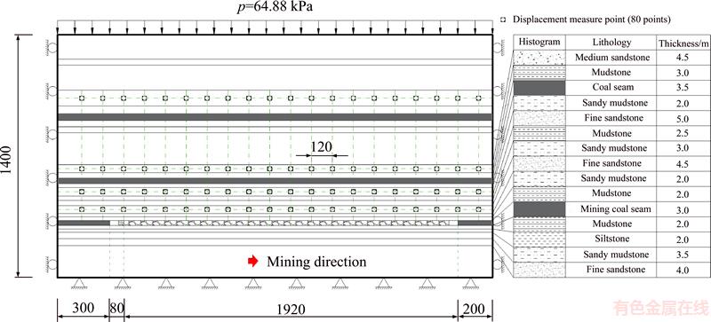
Figure 1 Experimental model for physical simulation (Unit: mm)
Table 1 Parameters of coal seam and key strata
3 Sequential collapse and deformation characteristics of strata overlying stope
3.1 Sequential collapse of immediate roof
Spatial location determines that the immediate roof stratum is the first to collapse. After the first immediate roof loses its coal seam constraint, initial collapse occurs when mining proceeds to 15 m. After that, mining is accompanied by collapse. The second immediate roof collapses when mining proceeds to 25 m. When mining proceeds beyond 30 m, the entire immediate roof strata collapse upon mining instead of sequential collapse.
3.2 Sequential collapse of key stratum
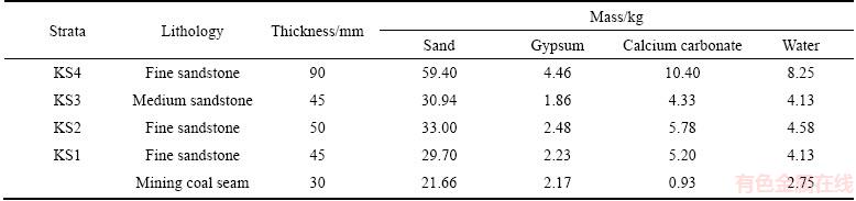
The main roof is 4.5 m-thick fine sandstone and is the first key stratum of the coal seam roof. The main roof has high strength and rigidity; it maintains a large span before rupture. As mining distance increases, the separation layer between the main roof and the immediate roof expands gradually. Initial collapse occurs when mining proceeds to 40 m (Figure 2(a)). Rupture blocks A, B and C form a ��three-hinged-arch�� temporary stable structure. When mining proceeds to 50 m, due to the increasing size of the span, block B experiences secondary breakage, and a stable ��voussoir beam�� structure is formed by the four blocks A, B, C and D (Figure 2(b)). Above the main roof are a 3.0 m-thick sandy mudstone stratum and a 2.5 m-thick mudstone stratum; their ultimate spans are far less than that of the main roof. After the main roof collapses, they also rupture and sink.
When mining proceeds to 80 m, the second key stratum collapses; overlying strata consisting of 2.0 m sandy mudstone, a 3.5 m coal seam and 3.0 m mudstone also collapse (Figure 3(a)). When mining proceeds to 90 m, the third key stratum collapses and triggers the collapse of overlying strata of 4.0 m silty sandstone, 2.0 m sandy mudstone and 2.5 m fine sandstone (Figure 3(b)). After that, the collapse range continues to expand. When mining proceeds to 110 m, overlying strata consisting of 5.0 m mudstone, 5.0 m silty sandstone, 3.5 m medium sandstone, 3.5 m sandy mudstone, 4.0 m coal seam, 2.5 m mudstone and 2.0 m silty sandstone collapse simultaneously (Figure 3(c)).
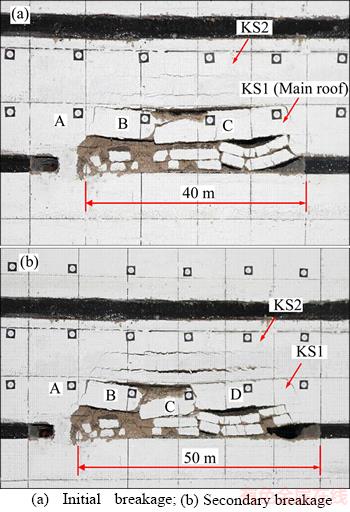
Figure 2 Collapse of KS1:
At this moment, the collapse strata at the top are the maximum key strata in the collapse zone and the fracture zone, i.e., 9.0 m-thick fine sandstone. This is called a master stratum in caving zone and fracture zone. This stratum can support a large ultimate span. Only when mining proceeds to 120 m does the master stratum start to rupture and trigger a wide range of overlying surrounding stratum collapse and subsidence (Figure 3(d)).
These findings show that each key stratum controls roof movement. When a key stratum collapses, multiple weak overlying strata also collapse [27, 28]. Key strata have different final spans and undergo sequential collapse from bottom to top as the working face progresses. Figure 4 shows the collapse process of key strata at different levels. Figure 4(a) shows that after an ��OX�� fracture, ��semi-OX�� fractures occur continually to produce cyclic pressure. Key strata at different locations have different fracture characteristics. Affected by the collapse angle, a key stratum at a higher location has a smaller ��O-X�� fracture size (Figure 4(b)). Sequential roof strata fractures occur from back to front and from bottom to top (Figure 4(c)), which causes multiple disturbances to gob-side entry retaining underneath (Figure 4(d)). Although the layers of the collapse key stratum heighten gradually, each fracture disturbance is based on the previous disturbances, and the influence of this superposed disturbance on the stress and deformation of the surrounding rock cannot be ignored. The scope of disturbed strata should be enlarged to fracture zone, while only the fracture disturbance of the main roof was paid attention to in the past.
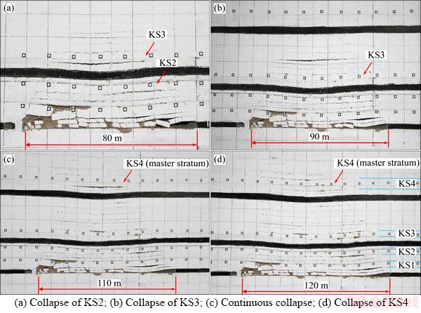
Figure 3 Collapse of key strata:
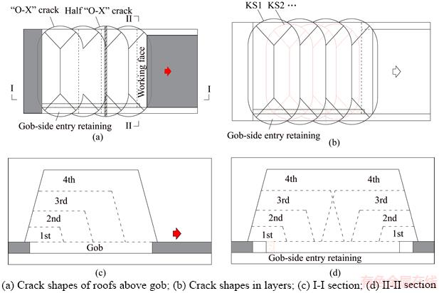
Figure 4 Collapse of key strata:
3.3 Key stratum deformation characteristic
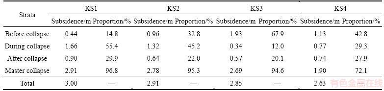
The maximum subsidence versus mining distance relations for each mining stage for 4 key strata are shown in Figure 5. Detailed data are listed in Table 2. The key stratum subsidence characteristic is as follows:
1) Before collapse, lower-layer strata have smaller flexure subsidence than higher-layer strata. Subsidence of the first to the fourth key strata before collapse comprises 14.8%, 32.8%, 67.9% and 42.8% of the total subsidence.
2) When a key stratum collapses, there is also significant rotational subsidence, which comprises 1/3�C1/2 of the total subsidence. When the first and the second key strata collapse, rotational subsidence comprises 55.4% and 45.2% of the total subsidence. When the third and the fourth key strata collapse, rotational subsidence comprises 12.0% and 29.3% of the total subsidence.
3) After a key stratum collapses, compressive deformation still occurs, which comprises 20%�C30% of the total deformation. In the test, compressive deformations of the first to the fourth key strata comprise 29.9%, 22.0%, 20.1% and 27.9% of the total deformation.
4) The master stratum controls low-layer rock mass deformation. After the stratum collapses, each key stratum underneath reaches maximum subsidence. When the master stratum collapses, the first to the third key strata comprise 96.8%, 95.3% and 94.6% of the total subsidence.
5) The main roof transmits rupture disturbances from other overlying key strata to the gob-side entry retaining. The main roof subsidence consists of three parts: flexure subsidence prior to rupture, rotational subsidence during rupture and compressive subsidence after rupture. Each comprises approximately 15%, 55% and 30% of the total subsidence. Based on the backstoping distance, the time ratio is 4:1:7.
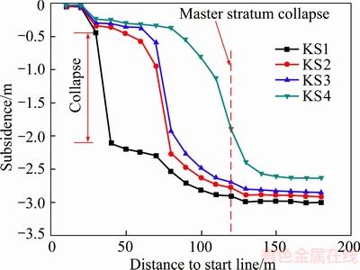
Figure 5 Relations between strata subsidence and mining distance
4 Disturbance of sequential overlying strata collapse to gob-side entry retaining
4.1 Determination of key stratum disturbance moment and cycle
The cycle of stratum movement-induced gob- side entry retaining disturbance starts upon backstoping and ends when the main roof deformation stabilizes [29]. Based on the above test, the main roof��s subsidence consists of three stages: flexure subsidence prior to rupture, rotational subsidence during rupture and compressive subsidence after rupture. Each key stratum collapse causes disturbance. Whether the main roof subsidence approaches its maximum value is determined by whether the master stratum collapses. Therefore, knowledge about the ultimate roof suspension distance of the master stratum helps to forecast the gob-side entry retaining disturbance cycle.
Table 2 Comparison of key strata subsidence in different stages
Based on the characteristics of the movement of the gob area��s overlying strata, a mechanical model of the key stratum fracture can be generated, as shown in Figure 6. The key stratum controls multiple weak overlying strata. Therefore, curvatures of all strata converge after deformation. Based on composite beam theory, the rock beam load q is as follows:
 (1)
(1)
where (qn)1 is the load from the n-th stratum on the first one; E1 and h1 are the elasticity modulus and thickness of the first stratum; and ��i, hi and Ei are the body force, thickness and elasticity modulus of the i-th stratum.
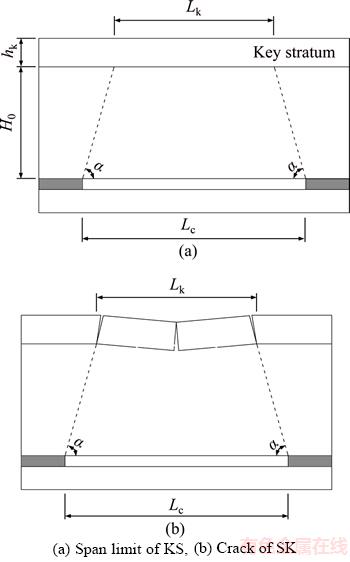
Figure 6 Mechanical model of KS:
Before rupture, a stratum is supported and clamped by a rock mass. It is treated as a beam with both ends being clamped. Based on the maximum tensile stress rule, the clamped end with the maximum bending moment and tensile stress fails first. At this moment, the key stratum��s rock beam length Lk is as follows:
 (2)
(2)
where hk and Rt are the key stratum��s thickness and tensile strength and q is the load on the key stratum, as determined by formula (1).
Based on the collapsed rock structure��s geometrical relations, the working face mining distance Lc at the moment of key stratum fracture is as follows:
 (3)
(3)
where H0 is the vertical distance between the key stratum and the coal seam and �� is the stope roof��s collapse angle.
Based on the working face��s progress velocity v and formula (3), the rupture disturbance time T for each key stratum is as follows:
 (4)
(4)
Therefore, key stratum parameters, such as the tensile strength, thickness, load, distance to the coal seam and the roof collapse angle, will affect the gob-side entry retaining disturbance moment; the master stratum��s parameters will affect the disturbance cycle. Formula (4) shows that the disturbance cycle is positively correlated to hk, Rt and H0 and negatively correlated to q and ��.
4.2 Effect on gob-side entry retaining��s bearing load
The strata overlying the gob area cause disturbance to the underlying gob-side entry retaining via the main roof. The primary form of disturbance is compressive subsidence. A gob-side entry retaining mechanical model is created, as shown in Figure 7. In the diagram, h1, m and h2 are the thicknesses of the immediate floor, coal seam and immediate roof; h is the entry height; Hg is the gob-area filling height; x0 is the horizontal distance from the main roof rupture base point to the entry; a and b are the widths for the gob-side entry retaining and filling wall; �� is the unsupported roof distance of the filling (due to insufficient filling and filling material condensation and contraction); L is the rupture block length; sb, sr and sc are the flexure subsidence, rotational subsidence and compressive subsidence of the main roof; and s is the total subsidence of the main roof.
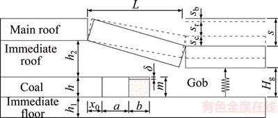
Figure 7 Mechanical model of gob-side entry retaining
Assume that K is the immediate roof crack- expansion coefficient and �� is the recovery ratio; then,
 (5)
(5)
In the entire gob-side entry retaining��s surrounding rock structure, the external roadside wall is under the most intense roof compression. Subsidence s�� at this position is
 (6)
(6)
where x0 and L are obtained via actual measurement or calculation [25]:
 (7)
(7)
where �� is the lateral pressure coefficient; ��0 and C0 are the internal friction angle and the cohesion of the interface between the coal seam and roof as well as the floor strata; k is the stress concentration coefficient; �� is the average volume weight of the overlying strata; H is the cover depth of the coal seam; and px is the support strength of the coal rib.
 (8)
(8)
where L�� is the cyclic pressure step and W is the working face width.
Assume that �� is the load on the outside wall and that E1, E and E2 are the equivalent elasticity moduli of the immediate floor, wall and immediate roof after mining damage. Based on Hooke��s law,
 (9)
(9)
Formula (9) shows that the roadside wall��s bearing load and roof subsidence are positively correlated. When a key stratum experiences sequential roof collapse, roof subsidence at each stage is significantly different. Therefore, the wall load increases in a non-linear pattern.
4.3 Effect on gob-side entry retaining��s deformation
After an immediate roof ruptures, it falls on the gob area��s bottom floor and loses mechanical connection with the lateral boundary. The weight of the remaining immediate roof is completely supported by the roadside wall and the lateral coal seam. Therefore, the gob-side entry retaining is affected by the immediate roof��s collapse and bears all the weight of the lateral residual immediate roof.
The stratum collapse area above the main roof gradually expands upward as the working face progresses. Each stratum��s collapse causes a gob-side entry retaining disturbance and results in a surrounding rock disturbance deformation. Figure 8 shows that when overlying strata experience sequential roof collapse, the entry undergoes continuous fluctuating deformation. Overlying strata activity has a long-term influence on the gob-side entry retaining. However, as the collapse area continues to expand toward a higher position, its influence gradually declines.
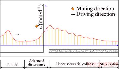
Figure 8 Deformation of gob-side entry retaining under sequential collapse
5 Control strategies for stability of gob- side entry retaining surrounding rock
5.1 ��Dual-layer�� proactive anchorage support
A stratum��s sequential roof collapse puts the gob-side entry retaining constantly under pressure. The surrounding rock structure needs sufficient self-stabilization and anti-disturbance capacity to prevent cracking instability. The shallow bearing layer is constructed from a high-strength short bolt support to provide excellent structural foundation for entry. The deep enhanced layer is constructed from a high-tension long anchorage cable to increase the thickness of the entry support ring and to further improve anchorage strength and self- stabilization capability. The bolt length should be at least half that of the entry span; the anchorage cable length should exceed twice that of the bolt length. ��Dual-layer�� proactive anchorage technologies complement each other and provide high pressure- resistance capabilities during stratum deformation, which effectively eliminates separation and constrains deformation.
5.2 Roadside filling with dynamic strength matching
Stratum subsidence deformation characteristics show that, after filling, the roadside wall is under roof compression and bears roof pressure. At different stages of roof stratum movement, the roadside wall bears different pressures. After roadside wall filling, it normally takes several days to reach the final strength. To prevent damage, the strength during the wall filling process should not be less than the roof load to ensure a dynamic match. This requires that the filled wall be strengthened at an early stage to ensure high strength.
5.3 Auxiliary support during disturbance period
Strata movement over the stope takes a long time, and the strength of the rock surrounding the entry is damaged continuously. During mining, the entry roof and floor will experience loose deformation. Individual hydraulic props, rigid roof beams and rigid pillar bases are combined to provide auxiliary support for the entry roof and floor, which effectively alleviates roof and floor deformation and pressure on the wall. Individual pillars have excellent high pressure-resistance capabilities. When the roof or the bottom floor experiences deformation, stress is transferred to the other side via the pillar to achieve mutual deformation control. The distance between auxiliary supports should exceed the ultimate span of the master stratum.
6 Engineering verification
6.1 Engineering conditions and assessment
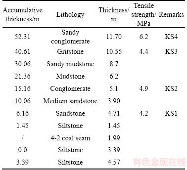
The Xiaoqing mine E1403 working face in the Tiefa mining area, China, has an inclined length of 230 m and a strike mining length of 767 m. Coal seams 4-2 are mined; the burial depth is between 357.5 and 452.3 m; the average thickness is 2.0 m; and the coal seam inclination angle is 2��C5��,with an average of 3��. The key strata occurring from the coal seam��s roof to floor are listed in Table 3.
Table 3 Occurrence of key strata in E1403 working face
6.2 Gob-side entry retaining implementation and support scheme
During the backstoping period, the gob-side entry retaining is affected at the haulage entry; the entry width is 5 m, and its height is 3.3 m. Figure 9 shows that the filling formwork support is used for filling. The filling formwork support consists of the end support and filling framework, which are connected via a hydraulic jack and can progress autonomously. The opening is made in the filling area 2�C3 m ahead of the working face to support the roof. After the working face passes, the filling framework is moved into position, and paste concrete is pumped into the framework by a filling pump.
��Dual-layer�� proactive anchorage support technology is deployed at the entry roof and coal rib, as shown in Figure 10. A shallow bearing layer is constructed from a bolt whose diameter is 20�C22 mm and length is 2.5�C2.8 m. A deep enhanced layer is constructed from an anchorage cable whose diameter is 21.8 mm and length is 4.3�C6.3 m. The bolt preload tension is 60 kN; the anchorage cable preload tension is 90 kN. The entry coal floor bolt and anchorage cable row space is 0.8 m, the roof bolt row space is 0.8 m, and the roof anchorage cable row space is 0.8 m; the layout follows the rule of ��3-4-3.�� The filling wall roof bolt row space is 0.8 m, and the anchorage cable row space is 1.6 m.
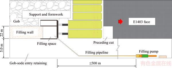
Figure 9 Sketch map of gob-side entry retaining in E1403 working face
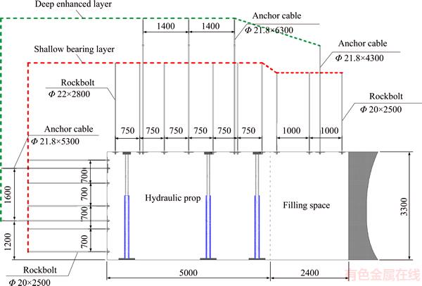
Figure 10 Supporting scheme of gob-side entry retaining in E1403 working face (Unit: mm)
Above the coal seam, KS1 is 4.7 m fine sandstone; KS2 is 5.1 m conglomerate; KS3 is 10.55 m coarse sandstone; and the master stratum (KS4) is 11.7 m sandy conglomerate. Based on formula (1), the load on KS1 before collapse is 137.3 kPa. The stratum collapse angle is 75��. These parameters are substituted into formulae (2) and (3) to calculate the main roof��s ultimate span Lk and the working face progress distance Lc at the first rupture (36.8 m and 37.6 m, respectively). Similarly, the ultimate spans of KS2, KS3 and KS4 are 40.1, 59.8 and 73.3 m. At the moment of rupture, the working faces�� progress distances are 45.5, 75.9 and 95.1 m. Therefore, the overlying strata sequential roof collapse-induced gob-side entry retaining disturbance distance is no less than 95.1 m. Considering the effect of advance abutment pressure, during the backstoping period in the area between 35 m in front of and 150 m behind of the working face, individual pillar auxiliary support is implemented.
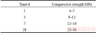
The roadside wall is 2.2 m wide and made from mine paste concrete filling material developed for gob-side entry retaining. The main components are stone, sand, cement, fly ash and additives; the components�� mechanical strengths are listed in Table 4. This material has the characteristics of early strengthening and high strength. One day after filling, the maximum strength can reach 7 MPa; after 28 d, its strength exceeds 22 MPa.
Table 4 Strengths of paste filling material
6.3 Result analysis
The actual measurement data pertaining to E1403��s gob-side entry retaining��s surrounding rock deformation velocity and deformation are shown in Figure 11. As shown, when the main roof collapses, the roof and floor reach the maximum deformation velocity of 28 mm/d. Due to the disturbance caused by the collapse of other key roof strata, deformation has not yet ended. Deformation does not stabilize until 102 m behind the working face. This proves that gob-area sequential roof collapse causes continuous disturbance deformation of the gob-side entry retaining. The entry deformation velocity declines in a fluctuating manner, which proves that as the collapse continues to move upward, the stratum movement-induced entry retaining disturbance subsides gradually. Figure 11(b) shows that the final deformation for both entry ribs is 284 mm; the final deformation for the roof and bottom is 449 mm. When the master stratum collapses, the two entry ribs and roof have deformations of 273 and 426 mm, which reach 96.1% and 94.9% of the final deformation. This proves that gob area roof stratum movement essentially reaches its maximum value when the master stratum ruptures.
Testing shows that x0=2 m, a=5 m, b=2.2 m, ��=0.05 m, L=24.9 m, h1=3.39 m, m=1.99 m, h=3.3 m, h2=1.45 m, K=1.4, E1=350 MPa, E=300 MPa, E2=350 MPa, and ��=0.95. Based on formulae (5) and (9), s=(0,1.31 m) and ��=(0,17.6 MPa). During the period of the field test, the backstoping entry retaining velocity is 5 m/d. Testing shows that sb:sr:sc=15:55:30 and that the deformation time ratio is 4:1:7. Variation curves of the wall load versus subsidence and time are shown in Figure 12(a). Wall load and roof subsidence are positively correlated. However, because the roof subsidence velocities in the three stages are different, the load growth rates are significantly different. During the entire gob-side entry retaining process, the maximum load on the wall does not exceed the minimum paste strength (Figure 12(b)). Field monitoring shows that the wall has not been severely damaged, and the entry maintains a healthy state (Figure 13). This means that the surrounding rock deformation is effectively controlled by the support technology.
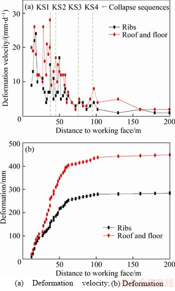
Figure 11 Deformation of gob-side entry retaining in E1403 working face:
7 Conclusions
1) The gob-area��s overlying strata exhibit the characteristics of sequential roof collapse. Each collapse is controlled by a key stratum. Key stratum subsidence consists of three parts: flexure subsidence prior to collapse, rotational subsidence during collapse and compressive subsidence after collapse. In the testing, the three parts for the main roof comprise 15%, 55% and 30% of the final subsidence. After the master stratum collapses, the main roof deformation reaches its maximum value, and mining essentially ends.
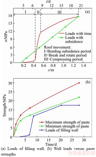
Figure 12 Curves of wall loads and paste strengths:
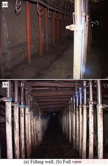
Figure 13 Images of E1403��s gob-side entry retaining:
2) The sequential roof collapse of the key stratum in ��two zones�� has a significant impact on the gob-side entry retaining disturbance cycle, filling wall load and entry deformation, while only the main roof was considered to have such impact. The calculation method for the disturbance cycle and wall load is determined. During the sequential roof collapse period for the overlying strata, the gob-side entry retaining exhibits fluctuating disturbance deformation. However, as the collapse position continues to move upward, the disturbance reduces gradually.
3) A gob-side entry retaining structure stability control strategy is proposed, which includes 3 measures: ��dual-layer�� proactive anchorage support, roadside filling with dynamic strength matching, and auxiliary support during the disturbance period.
4) The engineering practices for the gob-side entry retaining of the E1403 working face at the Xiaoqing mine verify the continuous disturbance of the gob-side entry retaining caused by the sequential roof collapse of the overlying strata. Entry deformation continues and stabilizes 102 m behind the working face. When the master stratum ruptures, the working face progress distance is 95.1 m. The two match well. When the master stratum collapses, entry deformations reach 96.1% and 94.9% of the final deformation, and disturbance essentially ends. After the 3 proposed control technologies are implemented, the entry is well controlled.
References
[1] YUAN Liang. Theory and practice of integrated pillarless coal production and methane extraction in multiseams of low permeability [M]. Beijing: China Coal Industry Publishing House, 2008. (in Chinese)
[2] XU Ying, CHEN Jin, BAI Jian-biao. Control of floor heaves with steel pile in gob-side entry retaining [J]. International Journal of Mining Science and Technology, 2016, 26(3): 527-534.
[3] HUA Xin-zhu, LI Ying-fu. Mechanics analysis on floor deformation of gob-side entry retaining and prevention and control of floor heave [J]. Journal of China Coal Society, 2016, 41(7): 1624-1631. (in Chinese)
[4] YE Gen-xi, ZHU Quan-jie, LI Shu-xia, YU Zheng-xing. Development and application of composite filling body in gob-side entry retaining with 1000 m-plus deep coal mine [J]. Journal of Mining & Safety Engineering, 2016, 33(5): 787-794. (in Chinese)
[5] SUN Xiao-ming, LIU Xin, LIANG Guang-feng, WANG Dong, JIANG Yu-lin. Key parameters of gob-side entry retaining formed by roof cut and pressure releasing in thin coal seams [J]. Chinese Journal of Rock Mechanics and Engineering, 2014, 33(7): 1449-1456. (in Chinese)
[6] YUAN Liang. The technique of coal mining and gas extraction by roadway retaining and borehole drilling [J]. Journal of China Coal Society, 2008, 33(8): 898-902. (in Chinese)
[7] YUAN Liang, GUO Hua, SHEN Bao-tang, QU Qing-dong, XUE Jun-hua. Circular overlying zone at longwall panel for efficient methane capture of multiple coal seams with low permeability [J]. Journal of China Coal Society, 2011, 36(3): 357-365. (in Chinese)
[8] ZHANG Nong, YUAN Liang, WANG Cheng, KAN Jia-guang, XU Xing-liang. Deformation characteristics and stability analysis of roof roadway in destressed mining [J]. Journal of China Coal Society, 2011, 36(11): 1784-1789. (in Chinese)
[9] YANG Hong-yun, CAO Shu-gang, WANG Shou-quan, FAN Ying-chong, WANG Shuai, CHEN Xian-zhe. Adaptation assessment of gob-side entry retaining based on geological factors [J]. Engineering Geology, 2016, 209: 143-151.
[10] KANG Hong-pu, WANG Jin-hua, LIN Jian. High pretensioned stress and intensive bolting system and its application in deep roadways [J]. Journal of China Coal Society, 2007, 32(12): 1233-1238. (in Chinese)
[11] KANG Hong-pu, WU Yong-zheng, LI Jian-bo. Analysis on mechanical performances and supporting function of combination components for rock bolting [J]. Journal of China Coal Society, 2010, 35(7): 1057-1065. (in Chinese)
[12] ZHANG Nong, YUAN Liang, HAN Chang-liang, XUE Jun-hua, KAN Jia-guang. Stability and deformation of surrounding rock in pillarless gob-side entry retaining [J]. Safety Science, 2012, 50(4): 593-599.
[13] QI Tai-yue, GUO Yu-guang, HOU Chao-jiong. Study on the adaptability for the pack-fillings of the gob-side entry retaining [J]. Journal of China Coal Society, 1999, 24(3): 256-260. (in Chinese)
[14] CHEN Yong, BAI Jian-biao, ZHU Tao-lei, YAN Shuai, ZHAO She-hui, LI Xue-chen. Mechanisms of roadside support in gob-side entry retaining and its application [J]. Rock and Soil Mechanics, 2012, 33(5): 1427-1432. (in Chinese)
[15] XUE Jun-hua, HAN Chang-liang. Strata behavior and control countermeasures for the gob-side entry retaining in the condition of large mining height [J]. Journal of Mining & Safety Engineering, 2012, 29(4): 466-473. (in Chinese)
[16] TAN Yun-liang, YU Feng-hai, NING Jian-guo, ZHAO Tong-bin. Design and construction of entry retaining wall along a gob side under hard roof stratum [J]. International Journal of Rock Mechanics and Mining Sciences, 2015, 77: 115-121.
[17] TAN Yun-liang, YU Feng-hai, NING Jian-guo, ZHAO Tong-bin. Adaptability theory of roadside support in gob-side entry retaining and its supporting design [J]. Journal of China Coal Society, 2016, 41(2): 376-382. (in Chinese)
[18] WANG Hong-sheng, ZHANG Dong-sheng, FAN Gang-wei. Structural effect of a soft-hard backfill wall in a gob-side roadway [J]. Mining Science and Technology (China), 2011, 21(3): 313-318.
[19] ZHANG Dong-sheng, MIAO Xie-xing, FENG Guang-ming, SONG Zhao-qian. Stability control of packing body for gob-side entry retaining in fully-mechanized coal faces with top-coal caving [J]. Journal of China University of Mining & Technology, 2003, 32(3): 232-235. (in Chinese)
[20] LI Xue-hua, JU Ming-he, YAO Qiang-ling, ZHOU Jian, CHONG Zhao-hui. Numerical investigation of the effect of the location of critical rock block fracture on crack evolution in a gob-side filling wall [J]. Rock Mechanics and Rock Engineering, 2016, 49(3): 1041-1058.
[21] ZHANG Zi-zheng, BAI Jian-biao, CHEN Yong, YAN Shuai. An innovative approach for gob-side entry retaining in highly gassy fully-mechanized longwall top-coal caving [J]. International Journal of Rock Mechanics and Mining Sciences, 2015, 80: 1-11.
[22] BAI Jian-biao, SHEN Wen-long, GUO Guan-long, WANG Xiang-yu, YU Yang. Roof deformation, failure characteristics, and preventive techniques of gob-side entry driving heading adjacent to the advancing working face [J]. Rock Mechanics and Rock Engineering, 2015, 48(6): 2447-2458.
[23] HAN Chang-liang, ZHANG Nong, LI Gui-chen, LI Bao-yu, WU Hai. Stability analysis of compound bearing structure of gob-side entry retaining with large mining height [J]. Chinese Journal of Geotechnical Engineering, 2014, 36(5): 969-976. (in Chinese)
[24] NING Jian-guo, WANG Jun, LIU Xue-sheng, QIAN Kun, SUN Bi. Soft-strong supporting mechanism of gob-side entry retaining in deep coal seams threatened by rockburst [J]. International Journal of Mining Science and Technology, 2014, 24(6): 805-810.
[25] HAN Chang-liang, ZHANG Nong, LI Bao-yu, SI Guang-yao, ZHENG Xi-gui. Pressure relief and structure stability mechanism of hard roof for gob-side entry retaining [J]. Journal of Central South University, 2015, 22(11): 4445-4455.
[26] SHEN Wen-long, BAI Jian-biao, WANG Xiang-yu, YU Yang. Response and control technology for entry loaded by mining abutment stress of a thick hard roof [J]. International Journal of Rock Mechanics and Mining Sciences, 2016, 90: 26-34.
[27] QIAN Ming-gao, SHI Ping-wu, XU Jia-lin. Mine pressure and strata control [M]. Xuzhou: China University of Mining and Technology Press, 2010. (in Chinese)
[28] QIAN Ming-gao, MIAO Xie-xing, XU Jia-lin, MAO Xian-biao. Theory of key strata in ground control [M]. Xuzhou: China University of Mining and Technology Press, 2003. (in Chinese)
[29] ZHANG Peng, HEASLEY K A. Elimination of boundary effect for laminated overburden model in pillar stability analysis [J]. Journal of Central South University, 2016, 23(6): 1551-1559.
(Edited by FANG Jing-hua)
���ĵ���
���ҷִο�����ؿ�����ĵ����Ŷ�����������ƶԲ�
ժҪ���ɿ�����������˶����ؿ�����Ĺؼ��Ŷ����ء����IJ����˲ɿ������ҵķִο�������������ؿ�����ĵ����Ŷ����������Ŷ��Ҳ��ɹ�ȥ���϶���������϶��������ģ��ʵ���ʾ��������Ҳ����Ź�������ƽ��������������ο��䣬�����ؿ�������ɶ���Ŷ��������еĸ����ؼ��������ÿһ�ο��䣬�����϶��³���Ϊ����ǰ�������³�������ʱ����ת�³��Լ����Ѻ��ѹ���³������Σ�ʵ���������ֱ������ֱ�ռ15%��55%��30%�����عؼ��������϶��ӽ�����³�ֵ���ؼ���ļ����������ؿ�������Ŷ�ʱ�����Ŷ����ڣ��϶��³���Ӱ���ų���ǽ����غɴ�С�����ҵķִο�����ʹ�ؿ�������ֳ������Ա��Ρ��������۷������õ��˹ؼ��㼫���ͳ���ǽ���غɵļ��㷽����������ؿ�����Χ���ȶ��Կ��Ƽ�����������˫�㡱����ê��֧����ǿ�ȶ�̬ƥ������Գ����Լ��Ŷ��ڼ�ĸ���֧��3������С���E1403�������ؿ�����Ĺ��̰�������֤���о����۵ĺ����ԡ�
�ؼ��ʣ��ִο��䣻�ؿ���������Ŷ��������ؼ��㣻�ȶ��Կ���
Foundation item: Project(51404251) supported by the National Natural Science Foundation of China; Project(BK20140198) supported by the Natural Science Foundation of Jiangsu Province, China; Project(PPZY2015A046) supported by the Top-notch Academic Programs Project of Jiangsu Higher Education Institutions, China; Project supported by the Priority Academic Program Development of Jiangsu Higher Education Institutions, China
Received date: 2017-09-09; Accepted date: 2018-02-11
Corresponding author: ZHANG Nong, PhD, Professor; Tel: +86�C13605210567; E-mail: zhangnong@126.com; ORCID: 0000-0001- 6961-0729
Abstract: Gob-area roof rupture movement is a key disturbance factor for gob-side entry retaining. The characteristics of gob-area sequential roof collapse of overlying strata and superposed disturbance mechanism for gob-side entry retaining are obtained via physical simulation and theoretical analysis, in which the scope of disturbed strata is enlarged from main roof to fracture zone. The experiment reveals that as a working face advances, roof strata sequentially collapse from bottom to top and produce multiple disturbances to gob-side entry retaining. Key strata among the overlying strata control each collapse. Main roof subsidence is divided into three stages: flexure subsidence prior to rupture, rotational subsidence during rupture and compressive subsidence after rupture. The amounts of deformation evident in each of the three stages are 15%, 55% and 30%, respectively. After the master stratum collapses, main roof subsidence approaches its maximum value. The final span of the key stratum determines the moment and cycling of gob-side entry retaining disturbances. Main roof subsidence influences the load on the filling wall. The sequential roof collapse of overlying strata results in fluctuations in the gob-side entry retaining deformation. Calculation formulae for the final span of the key stratum and the filling wall load are obtained via theoretical analysis. A control method for the stability of the gob-side entry retaining��s surrounding rock is proposed, which includes 3 measures: a ��dual-layer�� proactive anchorage support, roadside filling with dynamic strength matching and auxiliary support during disturbance. Finally, the gob-side entry retaining of the Xiaoqing mine E1403 working face is presented as an engineering case capable of verifying the validity of the research conclusions.
