

Comparative modeling of gas transport in isothermal chemical vapor infiltration process of C/SiC composites
WEI Xi(κ ��), CHENG Lai-fei(������), ZHANG Li-tong(����ͬ), XU Yong-dong(������), ZENG Qing-feng(�����)
National Key Laboratory of Thermostructure Composite Materials, Northwestern Polytechnical University,
Xi��an 710072, China
Received 10 April 2006; accepted 25 April 2006
Abstract:
Two comparative models taking into account of momentum, energy and mass transport coupled with chemical reaction kinetics were proposed to simulate gas transport in isothermal CVI reactor for fabrication of C/SiC composites. Convection in preform was neglected in one model where momentum transport in preform is neglected and mass transport in preform is dominated by diffusion. Whereas convection in preform was taken into account in the other model where momentum transport in preform is represented by Brinkman equations and mass transport in preform includes both diffusion and convection. The integrated models were solved by finite element method. The calculation results show that convection in preform have negligible effect on both velocity distribution and concentration distribution. The difference between MTS molarities in preform of the two models is less than 5��10-5, which indicates that ignorance of convection in preform is reasonable and acceptable for numerical simulation of ICVI process of C/SiC composites.
Key words:
C/SiC composites; modeling; isothermal chemical vapor infiltration; gas transport; convection;
1 Introduction
Carbon fiber-reinforced silicon carbide (C/SiC) composites have been developed as promising thermostructural materials for future spacecraft application due to their excellent properties [1,2]. Isothermal chemical vapor infiltration(ICVI) process is one of the most widely used techniques for fabrication of C/SiC composites[2]. Besides elaborate experimental work, numerical simulation has been regarded as a powerful tool for deep understanding of CVI process[3]. A number of works on modeling of CVI process have been reported[4-16]. Gas transport by convection in preform was taken into account in some models while it was neglected in other models. As we know, any reasonable simplification will reduces the computation time and leads to a better convergence, especially when solving the complicated system. Therefore, it is necessary to quantitatively model the effects of convection in preform on transport of momentum, energy and mass in a real and well-characterized CVI reactor and to make it clear whether the ignorance of convection in preform is acceptable.
In the present study, two models including momentum, energy and mass transport coupled with chemical reaction kinetics were proposed to comparatively simulate gas transport in ICVI process of C/SiC composites. One model (case 1) assumed that convection in preform is neglected. Whereas, convection in preform was taken into account in the other model (case 2) where Brinkman equations are adopted to depict momentum transport and mass transport in preform includes both diffusion and convection. The effects of convection in preform on gas transport in ICVI process of C/SiC composites can be determined by comparing the calculation results of the two models.
2 Mathematical model and fundamentals
The reactor is positioned vertically with inlet at the bottom and outlet at the top. Reactor length is 400 mm with z=0 located at the inlet and z=400 mm at the outlet. Only one preform is located in reactor with radius of 6 mm and length of 40 mm. Methyltrichlorosilane (CH3SiCl3, abbreviated as MTS) as precursor material, hydrogen as carrier gas and argon as diluting gas, are pumped into ICVI reactor and deposition of SiC matrix occurs in carbon fiber preform. In fact, SiC deposition process is very complex with gas phase reactions resulting in the formation of many Si- and C-bearing gas species. Since a sufficiently thorough knowledge of MTS pyrolysis chemistry is lacking, the overall chemical reaction is taken:
![]() (1)
(1)
2.1 Assumptions
Primary assumptions about preform structure and physical properties of gases are taken as follows.
1) There is a uniform porosity and fiber bulk fraction throughout preform before infiltration and preform is considered isotropy.
2) Compressibility of gases is neglected and gas flow is regarded as laminar flow.
3) Heat generation by chemical reaction is neglected and preform is regarded as isothermal.
4) Chemical reaction is regarded as an isothermal irreversible first-order reaction.
5) All of gases are considered ideal gases and obey the state equation of perfect gas.
2.2 Governing equations
The approach of this study is to propose models to comparatively simulate the physicochemical phenomena in free media of reactor and porous media of preform occurred at the beginning of ICVI process. Momentum transport in free media is described by momentum conservation equations on which the non-isothermal character of ICVI reactor is taken into account. Momentum transport in porous preform is neglected in case 1 and described by Brinkman equations in case 2. Energy transport is described by the energy conservation equation. Mass transport is described by mass conservation equation of MTS due to extreme dilution of H2 and Ar to MTS. Both convection and diffusion for mass transport in free media are taken into account. While in preform, only diffusion is taken into account in case 1 whereas both convection and diffusion are adopted in case 2. Adoption of steady state assumption for transport of momentum, energy and mass is taken due to the long infiltration time in ICVI process of C/SiC composites. Because of axial symmetry of geometry, the governing equations are formulated in cylindrical coordinates for a two-dimensional system (r and z) [17].
2.2.1 Gas transport in free media
The governing equations of gas transport in free media for case 1 are the same as those for case 2.
Energy transfer equation can be described as
![]() (2)
(2)
where cp is special heat capacity (J/(kg?K)), T is temperature (K), KT is thermal conductivity (W/(m?K)), and U is velocity vector in free media (m/s).
Mass conservation equation can be described as
![]() (3)
(3)
where C is molarity of MTS (mol/m3), and D is diffusion coefficient in free media (m2/s).
Momentum conservation equations and corresponding continuity equations are adopted to depict momentum transport, that is
![]() (4)
(4)
![]() (5)
(5)
where �� is density (kg/m3), �� is viscosity (kg/(m2?s)), and p is gas pressure (Pa).
2.2.2 Gas transport in porous preform
Momentum transport in preform is neglected and mass transfer is dominated only by diffusion in case 1:
![]() (6)
(6)
where Deff is effective diffusion coefficient of MTS in preform (m2/s), and R is reaction rate term (mol/(m3?s)).
Momentum transport in preform is represented by BRINKMAN equations in case 2, that is
![]() (7)
(7)
![]() (8)
(8)
where U1 is velocity vector in preform (m/s), k is permeability (m2), and p1 is gas pressure in preform (Pa).
Mass transport in preform includes both convection and diffusion in case 2:
![]() (9)
(9)
Because chemical reaction is regarded as first-order, R can be given as
![]() (10)
(10)
where K is first order reaction rate (m/s) for pyrolytic reaction of MTS, Sv is effective deposition surface of preform per unit volume (m2/m3).
2.3 Boundary conditions
2.3.1 Boundary conditions for momentum conservation equations
Supposing the fully developed laminar flow, the velocity along z axis at inlet follows parabolic profiles with v0 as average flow rate and Ri as radius of inlet:
 (11)
(11)
Gas pressure is set to a fixed value at outlet:
p=p0 (12)
No-slipping condition was adopted at reactor wall
u=0 (13)
Symmetry/slip condition was adopted at symmetry boundaries
u?n=0 (14)
where n is the unit normal vector.
At the boundaries between preform and free media, no-slipping condition was adopted in case 1, whereas the velocity and pressure at free media boundaries are equal to those at preform boundaries in case 2, that is
U=U1, p=p1 (15)
2.3.2 Boundary conditions for energy conservation equation
Temperature is set to a fixed value at inlet
T=T0 (16)
Convection flux dominates energy balance at outlet
![]() (17)
(17)
Energy flux is zero at symmetrical boundaries, that is
![]() (18)
(18)
There is a preheat zone near inlet. At reactor wall, temperature near outlet is lower than that at deposition zone due to heat dissipation from outlet and cover board. Temperature between the two zones is set to deposition temperature.
2.3.3 Boundary conditions for mass conservation equation
Molarity of MTS is set as a fixed value at inlet:
C=C0 (19)
Mass transport through outlet is dominated by convection
![]() (20)
(20)
Mass flux vertical to boundaries of reactor wall and symmetry is zero:
![]() (21)
(21)
Boundaries between free media and porous preform are considered internal boundaries, that is, mass flux keeps continuous across these boundaries.
3 Results and discussion
The combination of Eqn.(2) to Eqn.(21) makes up of the mathematical models. The governing equations are second order partial differential equation system, which are coupled and have to be solved simultaneously. The integrative model was implemented by finite element method. The simulation domain is meshed into 2214 triangle elements and quadratic Lagrange functions are taken as the shape functions. Important parameters in models, such as K, Sv, have been evaluated by WEI et al[16]. Operating conditions of ICVI process are as follows. Infiltration temperature is 1 273 K. Special flux of MTS, H2 and Ar is 1��10��10 and total pressure is 5 000 Pa. Initial porosity of preform is 55.6%.
Fig.1 shows flow field contours in ICVI reactor. It is shown from Fig.1(a) that no flow field exists in preform because the viscous transport and pressure gradient imposed on the preform are neglected and the outer surface of preform is set to the no-slipping boundary conditions in case 1. Whereas, in case 2, the viscous transport and pressure gradient in preform were taken into account, which leads to the velocity in preform not equal to zero though the values are with the magnitude of 10-3 m/s as shown in Fig.1(b).
Fig.2 shows the velocity profiles along cross section of z=0.25 m and z=0.27 m for case 1 and case 2 respectively. Cross section of z=0.25 m represents the upstream surface of preform and that of z=0.27 m represents the middle cross section of preform. From the comparison of the two figures, it is clearly shown that the velocity in preform in case 1 is strictly limited to zero, while that in case 2 is trivial but not equal to zero. The insert in Fig.2(b) highlights the velocity profiles in preform in case 2. The velocity at preform surface is higher than that at preform center in case 2 because there is more and more momentum lose from edge to center of preform due to the barrier effect of porous preform imposed on reagent gases. The maximum velocity in preform is only 9.554��10-3 m/s.
Fig.3 shows the partial pressure contours of MTS in ICVI reactor. It is clearly shown from Fig.4 that MTS pressure drop primarily focuses on the preform. The variation amplitude of MTS pressure in free media is less than 4.2% whereas that in preform is more than 18% in both case 1 and case 2. The lowermost MTS pressures are 185.887 4 Pa and 185.892 4 Pa in case 1 and case 2,
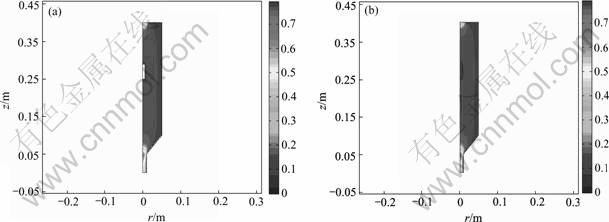
Fig.1 Flow field contours in ICVI reactor: (a) Case 1; (b) Case 2
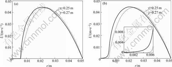
Fig.2 Velocity profiles at different cross sections: (a) Case 1; (b) Case 2
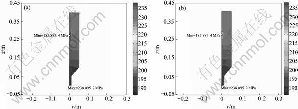
Fig.3 Partial pressures contours of MTS in ICVI reactor: (a) Case 1; (b) Case 2
respectively. From comparison of Fig.3(a) and Fig.3(b), the two partial pressure contours are analogical though the absolute value is trivially various. The trivial difference of MTS pressure resulting from the ignorance of convection in preform indicates that convection in preform has negligible effect on mass transport.
Fig.4 highlights the MTS molarity distribution in preform. It is shown that the two figures are highly analogical though the absolute value of MTS molarity is trivially different. The uppermost MTS molarities in preform are 0.021 644 and 0.021 646 mol/m3 for case 1 and case 2 respectively. Whereas the lowermost molarities occurring at z=0.273 7 m along symmetry axis of preform are 0.017 563 5 and 0.017 563 9 mol/m3 for case 1 and case 2 as shown in Fig.5. The error between molarities in preform for cases 1 and that for case 2 is less than 5��10-5, which also implies that convection in preform has negligible effect on mass transport in preform and mass transfer in preform is absolutely dominated by diffusion.
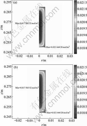
Fig.4 MTS molarity contours in preform: (a) Case 1; (b) Case 2
Due to the trivial effect of convection in preform on both momentum transport and mass transport, it is suggested that the ignorance of convection in preform is feasible and acceptable for numerical simulation of ICVI process of C/SiC composites.
4 Conclusions
Two comparative models were proposed to simulate the effects of convection in preform on gas transport in ICVI process of C/SiC composites. Convection in preform was neglected in one model where momentum transport in preform is neglected and mass transport in preform is dominated by diffusion. Whereas convection in preform was taken into account in the other model where momentum transport in preform is represented by BRINKMAN equations and mass transport in preform includes both diffusion and convection. The calculation results show that the convection in preform has trivial effect on both velocity distribution and MTS molarity distribution. The difference between MTS molarities in preform of the two models is less than 5��10-5, which implies that ignorance of convection in preform is reasonable and acceptable for numerical simulation of ICVI process of C/SiC composites.
References[1] Naslain R. Design, preparation and properties of non-oxide CMCs for application in engines and nuclear reactors: an overview [J]. Comp Sci & Tech, 2004, 64(2): 155-170.
[2] Zhang L T, Cheng L F, Xu Y D. Progress in research work of new CMC-SiC [J]. Aeronaut Manufact Eng, 2003, 1: 24-32.(in Chinese)
[3] Besmann T M, Sheldon B W, Lowden R A, Stinton D P. Vapor-phase fabrication and properties of continuous-filament ceramic composites [J]. Science, 1991, 253(6): 1104-1109. Fitzer R, Gadow R. Fiber-reinforced SiC [J]. Am Ceram Soc Bull, 1986, 65(2): 326-335.
[4] Tai N H, Chou T H. Modeling of an improved chemical vapor infiltration process for ceramic composites fabrication [J]. J Am Ceram Soc, 1990, 73(6): 1489-1498.
[5] Currier R P. Overlap model for chemical vapor infiltration of carbon in porous carbon substrates [J]. J Am Ceram Soc, 1990, 73(8): 2274-2280.
[6] Deepak, Evens J W. Mathematical model for chemical vapor infiltration in a microwave-heated preform [J]. J Am Ceram Soc, 1993, 76(8): 1924-1929.
[7] Sheldon B W, Besmann T M. Reaction and diffusion kinetic during the initial stages of isothermal chemical vapor infiltration [J]. J Am Ceram Soc, 1991, 74(12): 326-332.
[8] Chung G Y, McCoy B J. Modeling of chemical vapor infiltration for ceramic composites reinforced with layered, woven fabrics [J]. J Am Ceram Soc, 1991, 74(12): 746-751.
[9] STARR T L. Gas transport model for chemical vapor infiltration [J]. J Mater Res, 1995, 10(9): 2360-2366.
[10] Currier R P, Devlin D J, Morzinski J. Dynamics of chemical vapor infiltration in carbon fiber bundles [J]. J Adv Mater, 1996, 27(4): 13-24.
[11] Vaidyaraman S, Lackey W J, Agrawal P K, Starr T L. 1-D model for forced flow-thermal gradient chemical vapor infiltration process for carbon/carbon composites [J]. Carbon, 1996, 34(9): 1123-1133.
[12] Kulik V I, Kulik A V, Ramm M S, Makarov Y N. Modeling of SiC-matrix composite formation by isothermal chemical vapor infiltration [J]. J Cryst Growth, 2004, 266: 333-339.
[13] Wei X, Cheng L F, Zhang L T, Xu Y D. Numerical simulation of isothermal chemical vapor infiltration process for fabrication of C/SiC composites [J]. J Inorg Mater, In press.(in Chinese)
[14] McAllister P, Wolf E E. Simulation of a multiple substrate reactor for chemical vapor infiltration of pyrolytic carbon within carbon-carbon composites [J]. AICHE J, 1993, 39(7): 1196-1209.
[15] Reuge N, Vignoles G L. Modeling of isothermal-isothermal chemical vapor infiltration: effects of reactor control parameters on a densification [J]. J Mater Proce Tech, 2005, 166: 15-29.
[16] Wei X, Cheng L F, Zhang L T, Xu Y D, Zeng Q F. Numerical simulation for fabrication of C/SiC composites in isothermal CVI reactor [J]. Comput Mater Sci, Accepted.
[17] Bird R B, Stewart W E, Lightfoot E N. Transport Phenomena [M]. New York: John Wiley & Sons Publishers, 1960.
Foundation item: Project(90405015) supported by the National Natural Science Foundation of China; Project(50425208) supported by the National Young Elitists Foundation of China; Project([2005]33) supported by Program for Changjiang Scholars and Innovative Research Team in University of China
Corresponding author: WEI Xi; Tel: +86-29-88494616; Fax: +86-29-88494620; E-mail: libra_wei@163.com
