

Densification mechanism of chemical vapor infiltration technology for carbon/carbon composites
CHEN Jian-xun(�½�ѫ), XIONG Xiang(�� ��), HUANG Qi-zhong(������),
YI Mao-zhong(��ï��), HUANG Bai-yun(�Ʋ���)
State Key Laboratory of Powder Metallurgy, Central South University, Changsha 410083, China
Received 3 November 2006; accepted 16 January 2007
Abstract:
Carbon/carbon composites were fabricated using pressure-gradient chemical vapor infiltration(CVI) technology with propane (C3H6) as the carbon precursor gas and nitrogen (N2) as the carrier gas. The chemical process of deposition of pyrolytic carbon was deduced by analyzing the component of molecules in gas phase and observing the microstructure of deposition carbon. The results show that the process of deposition starts from the breakdown of C��C single bond of propene (C3H6), and forms two kinds of active groups in the heterogeneous gas phase reaction. Afterwards, these active groups form many stable bigger molecules and deposit on carbon fiber surface. At the same time, hydrogen atoms of the bigger molecules absorbed on carbon fiber surface are eliminated and the solid pyrolytic carbon matrix is formed in the heterogeneous reaction process.
Key words:
C/C composite; chemical vapor infiltration; densification mechanism;
1 Introduction
Carbon/carbon(C/C) composites have been used in aerospace applications because they possess some special properties of low density, high strength, low thermal expansion, excellent tribological properties and capability of withstanding temperature over 3 000 �� in many environment[1-3], for example, missile nose tips, solid rocket motor throats, rocket nozzles and aircraft brake disc[4-6]. Chemical vapor infiltration (CVI)[7-9] is commonly used to produce C/C composites. Namely, at high temperature, fill gas phase carbon precursor, for example, methane, propane, propylene, and benzene into the carbon fiber preforms. While the gas containing the carbon precursor flows from the inside towards the outside of the preforms, the carbon precursor gases decompose and deposit on carbon fiber surface so as to increase the density of the preforms.
At present, many studies in the field of C/C composites focus on how to improve the deposition rate, and there are many methods have been reported, for example, ISO-thermal gradient CVI[10], force flow-thermal gradient CVI[11], rapid direction diffused CVI[12], thermal gradient-pulse flow CVI[13] and pulse chemical infiltration[14]. Pressure-gradient CVI technology using the propene as the precursor gas[15] is an effective and often used way to manufacture the C/C composites in industry. However, the chemical decomposition process of carbon precursor affects not only the depositing rate, but also the matrix structure and depositing part in the preforms.
The purpose of this study is to ascertain the chemical decomposition process fabricated C/C composites using pressure-gradient CVI (PGCVI) technology with propene (C3H6) as the precursor.
2 Experimental
2.1 Carbon fiber preform preparation
Carbon fiber preforms, needle-punched felts that were often used to fabricate the aircraft brake disc, were utilized in present study. It was composed of continuous carbon fibers and chopped carbon fibers. The continuous carbon fiber was 12K-PAN based T-700 fiber from TOHO RAYON, Japan. The chopped carbon fiber was cut short of 12K-PAN based T700 from TORAY, Japan. The schematic diagram of needle-punched felt is shown in Fig.1.
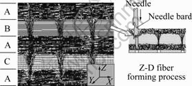
Fig.1 Schematic diagram of carbon fiber perform forming process
In Fig.1, part A is the layer of a randomly oriented chopped carbon fiber mat, parts B and C are the layers of continuous carbon fiber in X and Y direction respectively. During the needle punching process, many needles that penetrated vertically into each new superposed layer passed through the layer of chopped fiber web firstly. Some clusters of chopped fibers were caught and drawn through the layer of the continuous fibers and the chopped fiber mat by the needle barbs, and formed the needled fibers or Z-direction fiber in the preforms. When the needles were left up, the Z-direction fibers were leaved in the preforms because the needle moving direction is in the direction of its barb. With the increasing of needle-punched times and depth, more and more Z-direction fibers were penetrated into the preforms. The carbon fiber preforms were fabricated by using a desired number of superposed layers connected by the mutually mechanical binding and interlacing between Z-direction fiber with other fibers (continuous or chopped fibers). Finally, the preforms with a desired density of 0.60 g/cm3 were cut into size of d 146 mm��40 mm��20 mm.
2.2 CVI densification process
The PGCVI furnace used in the present work is shown in Fig.2. After heat treated at 2 100 ��, the preforms were placed in PGCVI furnace and densified by using propene as the carbon precursor gas and nitrogen as the carrier gas. The ratio of propene to nitrogen was about 1?3. The flow rate was about 60 L/min. The densification process was performed at the temperature range of 850-900 �� with a reduced pressure. During the densification process, the carbon precursor and carrier gases were fed into the PGCVI furnace from the reactant gas entrance, and passed through the preforms, finally exhausted from the top-vent.
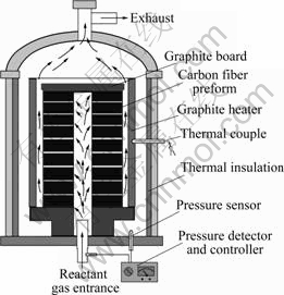
Fig.2 Schematic diagram of PGCVI furnace
At the beginning of the densification, the flow rate was only controlled for the high porosity in the preforms. Along with the densification processing, the density of preforms was increased; at the same time, the pressure gradient was formed gradually. At this stage, the pressure was detected and controlled by pressure detector and controller. After CVI, the density of C/C composites was up to 1.78 g/cm3. Finally, the C/C composites were heat-treated at 2 300 ��.
2.3 Gas ingredient analysis
During the densification process, the gas sampled from the exhaust vent by stochastic was analyzed using the gas phase chromatogram method. Finally, the deposit in the exhaust pipeline was analyzed using chemical method, too.
2.4 Microstructure of pyrolytic carbon
To study the property of C/C composite, the tested specimens were made by cutting the C/C composite from the central, and polished. Then an optical microscope (Polyvar-MET) and a SEM (JSM-6700F) were used respectively to observe its microstructure.
3 Results and discussion
3.1 Chemical reaction process
CVI is a very complex process, as shown in Fig.3, including homogeneous and heterogeneous chemical reactions, which relates to the generation and transport of active reactant species.
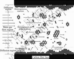
Fig.3 Schematic diagram of deposition process
The chemical process of CVI can be deduced by analyzing the gas ingredient of volatile by-products in the react chamber. The main gas ingredients and contents are as follows: cyclohexane, 100 mg/m3; benzene, 40 mg/m3; toluene, 100 mg/m3; cinnamene, 40 mg/m3. The solid deposit materials in the exhaust pipeline are naphthalene, anthracene and carbon soot.
From these results it can be concluded that the simple propene molecule forms many complex larger molecules during the CVI process. And these larger aromatic molecules are more stable than propene molecule at high temperature. The structure of propene molecule is as follows:
![]()
There are three kinds of bond in the propene molecule. Namely, C��H bond (strength: 414 kJ/mol), C=C double bond (strength: 610 kJ/mol) and C��C single bond (strength: 347 kJ/mol).
From above data, it is obvious that the strength of C��C single bond is more lower than that of C��H and C=C in propene molecule. Therefore, as shown in Fig.3, when the gas containing C3H6 and N2 molecules flows into the high temperature furnace, in the field of homogeneous gas phase in carbon fiber preforms, C3H6 molecule, C3H6 molecule and N2 collide each other with high frequency.
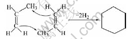
For C3H6, when two molecules have enough active energy and fit position, they firstly polymerize together and form a more stable molecule, cyclohexane. The chemical reaction of the formation process of cyclohexane in gas phase is as follows:
At the same time, for C3H6 and N2, N2 is a kind of inert molecule. C3H6 molecule gets energy, from colliding with N2, to break apart into two free active radicals from the weak bond of C��C. The two free active radicals are methylic and ethylene radicals respectively, and they have the properties of high energy and instability. They not only can collide other molecules to form some new free active radicals, but also can collide each other to form the C3H6 molecule. The formation process of ethylene free active radicals is as follows:
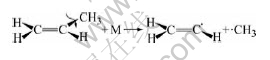
where M is the inert molecule N2.
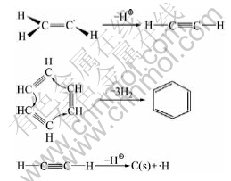
Ethylene free active radical is very active and in instability state. It releases a proton rapidly to form the stable acetylene molecule in gas phase. Then, when three acetylene molecules have the fit position, they can polymerize together and form a more stable molecule, benzene. In addition, it also undergoes dehydrogenation to form a solid carbon. The formation process of benzene is as follows:
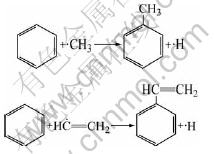
The benzene molecules form in gas phase collision with methyl free radical to form toluene and collide with ethylene free active radicals to form cinnamene molecule:
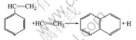
Cinnamene molecules, formed in gas phase, collide with ethylene free active radicals to form naphthalene molecule. Naphthalene molecule repeats above reaction to form many kinds of polycyclic aromatic hydrocarbon molecules such as anthracene and cyclopentapyrene:
All of these chemical reactions took place and carried on in the field of homogeneous gas phase, and solid powders and stable polycyclic aromatic molecules are formed.
3.2 Deposition mechanism of matrix carbon
Deposition process is the heterogeneous reaction occurred at the gas/solid interface. As shown in Fig.3, it produces the deposit carbon and by-product species.
At high temperatures (ranging from 850 to 900 ��), flowing through the carbon fiber preforms, the solid powders and stable polycyclic aromatic molecules form in the field of homogeneous gas phase collided or absorbed on carbon fiber surface. The solid carbon powders deposited on the carbon fiber surface can act as the crystallization centers. The stable polycyclic aromatic molecules are collected around the crystallization centers and gradually undergo dehydrogenation, finally change into the solid carbon. Figs.4 and 5 show the microstructures of the carbon/carbon composites prepared by PGCVI technology.
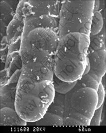
Fig.4 SEM microstructure of C/C composites
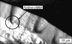
Fig.5 Optical microstructure of C/C composites
From Figs.4 and 5, it can be seen clearly that the crystallization and growth of depositing carbon on carbon fiber surface carry out around the active center.
The by-products from deposition surface are removed from the boundary layer into the flowing gas phase. At the same time, the other ingredient, i.e. methylic radicals, ethylene radicals respectively, are absorbed on carbon fiber surface to form the deposited carbon. But most of the molecules formed in the field of homogeneous gas phase, which are not absorbed on carbon fiber surface, are exhausted with carrier gas.
4 Conclusions
1) The process of deposition of carbon matrix is firstly the decomposition of C��C single band of C3H6, and the formation of two kinds of active groups in homo- geneous gas phase. Afterwards, the active groups form many stable bigger molecules and solid carbon powder.
2) The solid carbon powders form in gas phase deposited on the carbon fiber surface and act as the crystallization centers.
3) The stable polycyclic aromatic molecules are collected around the crystallization centers and gradually undergo dehydrogenation, finally change into the solid matrix carbon at high temperature.
References
[1] SCHMIDT D L, DAVIDSON K E, THEIBERT L S. Unique applications of carbon-carbon composite materials [J]. SAMPE Journal, 1999, 35(4): 51-62.
[2] BUCKLEY J D, EDIE D D. Carbon-Carbon Materials and Composites [M]. New Jersey: USA Noyes Press, 1993: 275.
[3] FITZER E. The future of carbon-carbon composites [J]. Carbon, 1987, 25(2): 163-190.
[4] BYRNE C, WANG Zhi-yun. Influence of thermal properties on friction performance of carbon composites [J]. Carbon, 2001, 39: 1789-1801.
[5] SHIN H K, LEE H B, KIM K S. Tribological properties of pitch-based 2-D carbon-carbon composites [J]. Carbon, 2001, 39: 959-970.
[6] QULI F A, THROWER P A, RADOVIC L R. Effects of the substrate on deposition structure and reactivity in the chemical vapor deposition of carbon [J]. Carbon, 1998, 36: 1623-1632.
[7] DELHAES P. Chemical vapor deposition and infiltration processes of carbon materials [J]. Carbon, 2002, 40: 641-657.
[8] CHOY K L. Chemical vapour deposition of coatings [J]. Progress in Materials Science, 2003, 48: 57-170.
[9] SAVAGE G. Carbon-Carbon Composites [M]. London: Chapman & Hall, 1992.
[10] LI He-jun, HOU Xiang-hui, CHEN Yi-xi. Densification of unidirectional chemical vapor infiltration [J]. Carbon, 2000, 38: 423-427.
[11] LEWIS J S, LACKEY W J, VAIDYARAMAN S. Model for prediction of matrix microstructure forced flow-thermal gradient CVI [J]. Carbon, 1997, 35(1): 103-112.
[12] LUO Rui-ying, YANG Cai-li, CHENG Ji-wei. Effect of preform architecture on the mechanical properties of 2D C/C composites prepared using rapid direction diffused CVI processes [J]. Carbon, 2002, 40: 2221-2228.
[13] BERTRAND S, LAVAUD J F, HADI R E, VIGNOLES G, PAILLER R. The thermal gradient-pulse flow CVI process: A new chemical vapor infiltration technique for the densification of fiber preporms [J]. Journal of the European Ceramic Society, 1998, 18: 857-870.
[14] JEONG H J, PARK H D, LEE J D, PARK J O. Densification of carbon/carbon composites by pulse chemical infiltration [J]. Carbon, 1996, 34(3): 417-421.
[15] CHEN Jian-xun, HUANG Bai-yun. Microstructure of carbon fiber perform and distribution of pyrolytic carbon by chemical vapor infiltration [J]. Trans Nonferrous Met Soc China, 2004, 14(4): 733-737.
Corresponding author: CHEN Jian-xun; Tel/Fax: +86-731-8830519; E-mail: jxchen@mail.csu.edu.cn
Abstract: Carbon/carbon composites were fabricated using pressure-gradient chemical vapor infiltration(CVI) technology with propane (C3H6) as the carbon precursor gas and nitrogen (N2) as the carrier gas. The chemical process of deposition of pyrolytic carbon was deduced by analyzing the component of molecules in gas phase and observing the microstructure of deposition carbon. The results show that the process of deposition starts from the breakdown of C��C single bond of propene (C3H6), and forms two kinds of active groups in the heterogeneous gas phase reaction. Afterwards, these active groups form many stable bigger molecules and deposit on carbon fiber surface. At the same time, hydrogen atoms of the bigger molecules absorbed on carbon fiber surface are eliminated and the solid pyrolytic carbon matrix is formed in the heterogeneous reaction process.
