

Use of nitrogen gas in high-speed milling of Ti-6Al-4V
KE Ying-lin(��ӳ��)1, 2, DONG Hui-yue(����Ծ)1, LIU Gang(�� ��)1, ZHANG Ming(�� ��)1
1. Zhejiang Provinvicial Key Laboratory of Advanced Manufacturing Technology, Zhejiang University,
Hangzhou 310027, China;
2. State Key Laboratory of Fluid Powder Transmission and Control, Zhejiang University,
Hangzhou 310027, China
Received 30 June 2008; accepted 9 November 2008
Abstract:
To inhibit chips burning in the high-speed cutting of Ti-6Al-4V, nitrogen gas with 0.7 MPa pressure was ejected at the milling zone. The high speed flowing of nitrogen gas speeds up the chips leaving, and prevents the chips from burning at the same time. By this method the cutting force is reduced. Especially, the temperature increment of the finished surface is smaller than 5 ��. This prevents the increase of hardness, improves the roughness of the finished surface, and reduces the tools wear. Comparing and analyzing the morphology and color of chips, which are obtained from the high-speed machining of Ti-6Al-4V with and without nitrogen gas ejection, show the action mechanism of nitrogen gas during the high-speed machining of titanium alloy, and it is concluded that nitrogen gas can be used to realize the proper high-speed milling of Ti-6Al-4V titanium alloy.
Key words:
Ti-6Al-4V; high-speed machining; burning; nitrogen gas;
1 Introduction
To improve the assembly accuracy and mobility of fighter plane, stock is left after titanium alloy part is machined in numerical control workshop, and this stock is cut off during flexible assembly. To keep the position accuracy of fighter plane, cutting force is demanded as much as small, and liquid lubrication oil is not allowed to use. The efficiency of original machining method is low and cutting force is large, so it cannot meet the demand of flexible assembly. The aim of the present work is to solve these problems.
The major application of titanium alloys is in the aerospace industry due to their high specific strength at elevated temperatures and exceptional corrosion resistance. However, titanium alloys were classified as ��difficult-to-machine�� material owing to their several inherent properties, such as low thermal conductivity, low elastic modulus, high strength at elevated temperature and high chemical reactivity with many cutting tool materials during machining process. Very high temperature in the machining zone can damage the finished surface of titanium alloys easily. Another impairment caused by the high temperature is the melting of titanium alloy chips and adhesion to the tool and on the machined surface.
Lots of studies have been done on the machining of titanium alloys, including tool wearing[1-3], chip forming (especially serrated chips)[4], and the optimization of machining parameters[5-6]. ZHAO et al [7] did some studies about tool wearing in high speed using nitrogen-oil-mist as a cutting medium. The highest cutting speed was 400 m/min. BAKER[4], JIANG and SHIVPURI[8] simulated the shaping process of titanium alloy. They found that the chips were discontinuous when cutting with slow speed, while they were serrated when cutting with high speed. The highest machining speeds were 600 m/min in FEM mode and 240 m/min in experiment. CHE-HARON and AWAID[6] researched the integrity, roughness, micro-hardness and micro- structure of the machined surface. The highest cutting speed selected in their experiment was 100 m/min[6]. VARGAS PEREZ[3] studied the wear mechanism of WC inserts in face machining of titanium alloy. He demonstrated that this alloy had marked strain rate sensi-tivity and tendency to strain hardening when the face was milled under certain cutting conditions[3]. The alloy chips were prone to burning in high speed machining, and the chips would burn more severely if lubrication oil was used. The burnt chips would adhere to cutting edges, causing tool to wear off rapidly, and the machined surface integrity to be impaired at the same time. Furthermore, liquid lubrication oil is forbidden to use in the assembly process of airplane. So, the cutting speed of titanium alloy in most studies was very low, around 100 m/min[9-10]. HONG et at[11] studied cryogenic machining of titanium alloy Ti-6Al-4V to improve tool life, and a special setup was designed. YILDIZ and NALBANT[12] reviewed the cryogenic cooling in machining processes of Ti-6Al-4V.
In this study, Ti-6Al-4V was machined with the cutting speed of 565 m/min, and nitrogen gas was ejected to the machining zone. This is a higher speed machining technology for cutting Ti-6Al-4V[13].
2 Experiment of high speed machining Ti-6Al-4V
The workpiece material was Ti-6Al-4V. Table 1 lists the machining conditions of cutting Ti-6Al-4V with high speed operation with milling hole diameter enlarged from 20 mm to 26 mm. Fig.1 shows the experimental setup. The cylinder workpiece was clamped with a fixture mounted on the quartz three-component dynamometer of KISTLER 9257B type. Experiments of cutting Ti-6Al-4V with and without nitrogen gas ejection were done. The pressure of nitrogen gas was 0.7 MPa.
Table1 Machining conditions of cutting Ti-6Al-4V with high speed
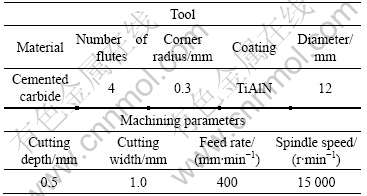
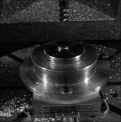
Fig.1 Experimental setup of cutting Ti-6Al-4V
3 Abrasion on tool rake face
Chips wrapped around the tool tip, and burning happened in dry machining of Ti-6Al-4V (without nitrogen gas), as shown in Fig.2(a). Although the majority of machining heat was taken away by chips during high-speed machining, if the chips could not be removed immediately, the burning chips would adhere to the cutting edge strongly, and the cutting edge would wear off rapidly in the high speed revolution process. If the cutting operation was continued with the severe worn tool, the workpiece material would melt.
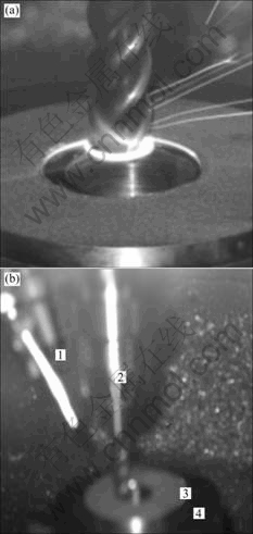
Fig.2 Experiment of milling hole on Ti-6Al-4V: (a) Without nitrogen gas; (b) With nitrogen gas (1��Nitrogen gas nozzle; 2��Milling tool; 3��Workpiece; 4��Fixture)
There was no flaming chips when nitrogen gas was ejected to the machining zone (Fig.2(b)), because the flowing nitrogen gas with 0.7 MPa covered the whole machining zone and oxygen was prevented to approach. At the same time, the drainage of Ti-6Al-4V chips was improved. Without nitrogen gas, the cutting time was less than 10 min before the tool was worn heavily; and the melt chips were adhered to the tool rake face (parts in the two ellipses) (Fig.3(a)). Fig.3(b) shows the condition of rake face when cutting with nitrogen gas ejection for about 1 h. Because the cutting time was so long that the tool was worn mildly, but there was not adherent chips in the tool.
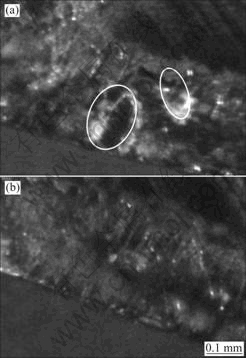
Fig3 Microimages of tools rake face: (a) Without nitrogen gas; (b) With nitrogen gas
4 Analysis of cutting force and surface roughness
The depth of the hole was 25 mm. Because the nitrogen gas nozzle was not designed specially, nitrogen gas could not able to be ejected to the destination when the hole was deeper than 20 mm. Cutting force, shape of chips, and the integrity of the machined surface when cutting with nitrogen gas were all different from those when cutting without nitrogen gas. Fig.4 and Fig.5 show the cutting force curves when machining with and without nitrogen gas, respectively. It is obvious that the cutting force was greater when cutting without nitrogen gas (the maximum of 162 N) than those when cutting with nitrogen gas (the maximum of 109 N). The reason of this is that without nitrogen gas, the chips congregated
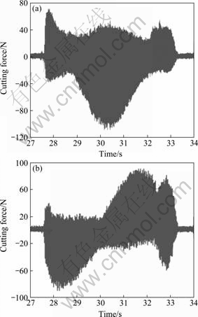
Fig.4 Measured cutting force in machining of Ti-6Al-4V with nitrogen: (a) In X direction (b) In Y direction
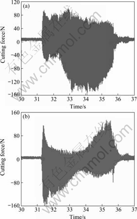
Fig.5 Measured cutting force in machining of Ti-6Al-4V without nitrogen: (a) In X direction; (b) In Y direction
around the cutting edge, and the condition of chip drainage was very poor. The amount of machining heat was generated greatly and the chips were melted and adhered to the cutting edge. Then the cutting force increased consequently.
When machining was finished, the roughness of the machined surface was measured. The roughness of the surface was 0.22 ��m when using nitrogen while it was 3.5 ��m without nitrogen gas. This is because that when nitrogen gas was not able to arrive at the machining zone, lots of chips that absorbed a large amount of heat and could not be removed immediately would burn. Then the burning chips adhered to cutting edges and machined surface. Fig.6 shows two morphologies of finished surfaces. One was obtained when nitrogen gas was used, and the other was obtained when nitrogen gas could not arrive at the machining zone (especially the partial surface in the ellipse).
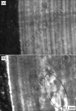
Fig.6 Morphologies of finished surface of high-speed machining of Ti-6Al-4V: (a) With nitrogen gas; (b) Without nitrogen gas
5 Analysis of chip configuration
Though the same machining parameters were used, the configuration of chips obtained with and without nitrogen gas ejection was different greatly. Fig.7 shows the difference. When there was no nitrogen gas, the shape of chips was continuous and undee. It was obvious that the chip was composed of several serrated small chips. This characteristic was more obvious when observing the chip from its back side(Fig.8). The reason why this configuration was formed during high speed machining of Ti-6Al-4V can be explained as follows. Chips that absorbed the majority of machining heat and could not be removed away immediately from the machining zone would be softened and burnt by the high temperature when the edge cut into the material. The temperature softening effect in the primary shear zone was especially stronger than the other part and resulted in the plastic instability, leading to catastrophic shear failure along the shear surface. So, after every constant length along the cutting edge trajectory, a serrated chip would be formed[8,14]. A longer chip composed of several serrated parts was generated when an edge cut out the workpiece material. The fact that the chip length was almost the same as the length of cutting layer showed that the chip did not break from an edge cutting-into to cutting-out workpiece material. The dark blue color of the chip showed it was burnt in the machining process. The continuous and burnt chips adhered to cutting edge and machined surface would result in the poor integrity of machined surface, and increased cutting force at the same time. This conclusion agreed well with the analysis of cutting force.
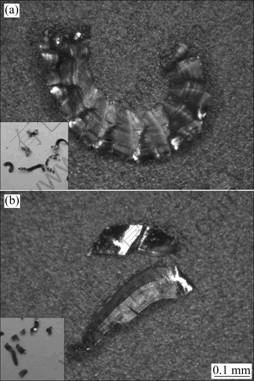
Fig.7 Configuration of chips under high speed machining of Ti-6Al-4V: (a) Without nitrogen gas; (b) With nitrogen gas
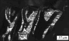
Fig.8 Back side of chip in Fig.7(a)
Fig.7(b) shows the shape of chips obtained when nitrogen gas arrived at the machining zone. It was every obvious that the color, length and shape of the chips were changed. The length was about 1/3-1/4 that with nitrogen gas; the color was even gray; and the shape was not serrated. All these differences showed that, in an edge cutting process, the cutting layer was broke into 3-4 parts, and the chips did not burn but was removed away from machining zone because the existence and high speed flowing of nitrogen gas. So, the chips did not adhere to the cutting tool, and the abrasion of tool could be improved greatly. The surface integrity could be polished correspondingly.
The majority of machining heat was absorbed by chips. With nitrogen gas, not only chip burning was prevented but also machining heat was removed by the flowing nitrogen gas. So, when the surface was just finished, the temperature increment was very low (nearly the room temperature), which could prevent the increase of hardness on the top layer of the finished surface.
In general, elements that affect chip shape include workpiece material properties, machining parameters and tool geometry[15]. But based on above analysis, nitrogen gas is another factor that affects chip shape of titanium alloys.
6 Conclusions
1) When nitrogen gas was not used, the chip shape was continuous and serrated. The chips were burnt in the cutting process.
2) When nitrogen gas arrived at machining zone with high flowing speed, the chips did not burn and were broke into 3-4 parts and were removed away immediately.
3) With nitrogen gas, the adhesion between chip and cutting edge was prevented, and the abrasion condition of tool was improved. The integrity of machined surface was increased.
References
[1] JAWAID A, SHARIF S, KOKSAL S. Evaluation of wear mechanisms of coated carbide tools when face milling titanium alloy [J]. Journal of Materials Processing Technology, 2000, 99: 266-274.
[2] DEARNLEY P A, SCHELLEWALD M, DAHM K L. Characterisa- tion and wear response of metal-boride coated WC-Co [J]. Wear, 2005, 259: 861-869.
[3] VARGAS PEREZ R G. Wear mechanisms of WC inserts in face milling of gamma titanium aluminides [J]. Wear, 2005, 259: 1160-1167.
[4] BAKER M. The influence of plastic properties on chip formation [J]. Computational Materials Science, 2003, 28: 556-562.
[5] RIBEIRO M V, MOREIRA M R V, FERREIRA J R. Optimization of titanium alloy (6Al-4V) machining [J]. Journal of Materials Processing Technology, 2003, 143/144: 458-463.
[6] CHE-HARON C H, AWAID A J. The effect of machining on surface integrity of titanium alloy Ti-6%Al-4% V [J]. Journal of Materials Processing Technology, 2005, 166: 188-192.
[7] ZHAO Wei, HE Ning, LI Liang, MAN Zhong. Experimental study on high speed milling of Ti-6Al-4V alloy with nitrogen-oil-mist [J]. Journal of Nanjing University of Aeronautics & Astronautics, 2006, 38(5): 634-638. (in Chinese)
[8] JIANG H, SHIVPURI R. Prediction of chip morphology and segmentation during the machining of titanium alloys [J]. Journal of Materials Processing Technology, 2004, 150: 124-133.
[9] NABHANI F. Machining of aerospace titanium alloys [J]. Robotics and Computer Integrated Manufacturing, 2001, 17: 99-106.
[10] VENUGOPAL K A, PAULB S, CHATTOPADHYAY A B. Growth of tool wear in turning of Ti-6Al-4V alloy under cryogenic cooling [J]. Wear, 2007, 262: 1071-1078.
[11] HONG S Y, MARKUS I, JEONG W C. New cooling approach and tool life improvement in cryogenic machining of titanium alloy Ti-6Al-4V [J]. International Journal of Machine Tools & Manufacture, 2001, 41: 2245-2260.
[12] YILDIZ Y, NALBANT M. A review of cryogenic cooling in machining processes [J]. International Journal of Machine Tools and Manufacture 2008, 48(9): 947-964.
[13] SU Y, HE N, LI L, LI X L. An experimental investigation of effects of cooling/lubrication conditions on tool wear in high-speed end milling of Ti-6Al-4V [J]. Wear, 2006, 261: 760-766.
[14] BAKER M, ROSLER J, SIEMERS C. Finite element simulation of segmented chip formation of Ti-6Al-4V [J]. Journal of Manufacturing Science and Engineering, 2002, 124(5): 485-488.
[15] LI Liang. Study on the mechanism and process of high speed milling of titanium alloys [D]. Nanjing: Nanjing University of Aeronautics and Astronautics, 2004. (in Chinese)
Foundation item: Project(50705085) supported by the National Natural Science Foundation of China; Project(2006AA04Z147) supported by the National High-tech Research and Development Program of China
Corresponding author: DONG Hui-yue; Tel: +86-571-87953929; E-mail: donghuiyue@zju.edu.cn
DOI: 10.1016/S1003-6326(08)60307-6
(Edited by YANG Bing)
Abstract: To inhibit chips burning in the high-speed cutting of Ti-6Al-4V, nitrogen gas with 0.7 MPa pressure was ejected at the milling zone. The high speed flowing of nitrogen gas speeds up the chips leaving, and prevents the chips from burning at the same time. By this method the cutting force is reduced. Especially, the temperature increment of the finished surface is smaller than 5 ��. This prevents the increase of hardness, improves the roughness of the finished surface, and reduces the tools wear. Comparing and analyzing the morphology and color of chips, which are obtained from the high-speed machining of Ti-6Al-4V with and without nitrogen gas ejection, show the action mechanism of nitrogen gas during the high-speed machining of titanium alloy, and it is concluded that nitrogen gas can be used to realize the proper high-speed milling of Ti-6Al-4V titanium alloy.
