

Simulation of smoke flow and longitudinal ventilation in tunnel fire
YANG Gao-shang(�����)1, AN Yong-lin(������)1, PENG Li-min(������)1, ZHANG Jin-hua(�Ž���)2
1. School of Civil Engineering and Architecture, Central South University, Changsha 410075, China;
2. Hunan Province Communication Planning Survey and Design Institute, Changsha 410008, China
Received 20 August 2005; accepted 18 March 2006
Abstract:
Understanding the characteristics of smoke flow in tunnel fire is very important for tunnel safety. The characteristics of tunnel fire were analyzed. The smoke development in different situations of an engineering example was simulated using commercial CFD software PHOENICS 3.5 by field modeling method. The spreading rules and characteristics of concentration field and temperature field of smoke flow with different longitudinal ventilation speeds were studied, which may provide the theoretical background for evacuation design in tunnel fire. The effective measures of fire rescue and crowd evacuation were also described.
Key words:
tunnel safety; tunnel fire; smoke flow; longitudinal ventilation; simulation;
1 Introduction
The tunnel is one of the important facilities of railroad and highway transportation, and also a throat of railroad and highway. With the development of transportation, there are more and more tunnels. Although the tunnel fire occurs seldom, but the potential danger of life safety is tremendous once a fire occurs in tunnel. The tunnel fire has some characteristics such as the burnable condition is complicated, the fire spreads quickly, the hot smoke expels hardly, the fire calories concentrate, the heat dispels slowly, and the temperature of air current increases very quickly. Additionally, the narrow and enclosed special construction inside the tunnel leads to the vehicle and personnel to evacuate hardly. Usually, the scope involved in the fire is very large and the loss of economy and personnel are heavy once the fire occurs. In the last 30 years, many tunnel fires occurred around the world[1,2], which have already attracted the researcher��s high attention, and some studies on experiment and simulation calculation[3-5] have been made. Through a large quantity of experiments in the model and abandoned tunnels, many precious firsthand data[6-8] have been obtained. Studying on smoke development regulations of the tunnel fire would be helpful to decrease the fire loss, guarantee the personnel life safety and the tunnel��s safety operation.
It is difficult to quantify the concentration changes of the fire smoke by model experiment, and it is impossible to draw the temperature field figure in the tunnel fire. Numerical simulation can make it up, which has the advantages such as accuracy, convenience, and cost-saving. So it has drawn broad recognition. The numerical simulation of an engineering example is made with the use of commercial CFD software PHOENICS 3.5 in this paper. The spreading rules and characteristics of concentration field and temperature field of the tunnel fire with different longitudinal ventilation speeds were studied, which may provide some reference for evacuation design in tunnel fire. The effective measures of fire rescue and crowd evacuation were also put forward.
2 Field analysis of numerical simulation
When the tunnel fire occurs, the temperature field and density field of the influenced surroundings are changed due to the heat effect of the hot smoke, which induces convection because of the gravity field effect. At this time the smoke flow of fire is mainly controlled by float-rise force and ventilation. Two kinds of influence factors affect and interact mutually, and produce complicated fluxion, which contains flow, mass and heat transfer, chemical reactions and their interactions. Almost all of the actual burnable processes are overfall process. Certainly, the flow and heat transfer process abide by the basic rule of the objective world, such as conservation of mass and energy and momentum. Therefore, the equations of the continuity, energy, movement and state are made up of the basic equations of the flow and heat transfer process, which plus some composition equations should constitute control equation groups of the smoke flow, mass and heat transfer. The control equation groups of the main variables (such as density and temperature) needed by the solution of the fluid and heat transfer problems can be shown in following general form[9, 10]:
![]() (1)
(1)
where �� is general variable, which can represent solution variable, such as u, v,w, T; ![]() is generalized diffusion coefficient;
is generalized diffusion coefficient; ![]() is generalized fountain item.
is generalized fountain item.
3 Physical model and calculation condition
3.1 Physical model
The calculating object of this numerical simulation is the Xue-feng Mountain Tunnel, about 7 km long, which is the second longest tunnel in China currently, as well as the controlling project of Shao-Huai section of the Shang-Rui freeway. Because the average space between the cross passages is 250 m, the furthest evacuation distance is 250 m. Therefore, the fire simulation calculation only considers the smoke development condition of the fire source neighborhood and its downstream 250 m scope. The tunnel length adopted for calculation is 300 m. For the convenience of simulation, the model of Xue-feng mountain tunnel is simplified. Then the cross section is a rectangle of 10 m��2 m plus a semicircle of 5 m diameter. The calculated area is 7 m��10 m��300 m. The tunnel cross section upstream the fire source is taken as a ventilation entrance. It is supposed that the tunnel prolongs 300 m along the x axis direction while the cross section in the end is the export boundary.
Because Xue-feng Mountain Tunnel is two holes and one-direction road, and the large and medium-sized passenger cars account for a large proportion in the transportation, and the number of passengers is large, the authors take passenger car as a fire source, whose largest fire source scale[11,12] is 20 MW, which belongs to the medium-sized fire scale. The fire source position is located at the middle axis, its size is 4 m��2 m��2 m, located at the position of x=20 m. The model sketch is shown in Fig.1. Probe point T1 is put on the middle vault. Probe point T2 is put on the position of human body height over road middle line. Probe point T3 is put on the position of human body height of passengers concentration position. The position of probe point located at x axis is: x=5, 10, 15 (5 m upstream the fire source), 20, 25 (5 m downstream the fire source), 30, 40, 60, 90, 120, 145 (25 m downstream the fire source), 180, 220, 270 (250 m downstream the fire source).
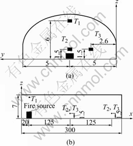
Fig.1 Probe point distribution of transection(a) and vertical section(b) of model (unit: m)
3.2 Calculation condition
1) Initial conditions
The fire smoke flow is variable. The fluxion parameter �� of every point in the flow field at one fixed time (such as initial state) must be given for solution. At the initial state everywhere in the tunnel (t=0), suppose: P=P0, u=u0, v=0, w=0, t=18 ��.
2)Boundary conditions
�� Tunnel inlet: The wind velocity at the tunnel inlet is the longitudinal ventilation speed, the temperature is t=18 ��, and the smoke concentration is zero.
�� Tunnel structure surface: On the tunnel structural surface, no slide boundary conditions are taken, namely the surface velocity is zero, and the surface logarithm rates are adopted for the surface function. The roughness value is taken as 0.01, and for the conservative consideration, the surface is adiabatic, that is, there is no heat transfer.
�� Tunnel outlet: The sufficient development condition is used in the calculation of outlet boundary. The parameters of the nodes in the outlet cross section have no influence on the parameters of the approaching nodes. The relative pressure is set to be zero and the temperature is 18 ��.
3) Gridding and iteration
�� Gridding: Uniform meshes are adopted and the calculation volume is divided into 63 000 control volumes. The initial internal ambient temperature is supposed to be 18 ��.
�� Iteration: Every 10 s is a time step within internal iteration 40 steps and the total steps are 60.
4 Simulation conditions and calculation analysis
4.1 Simulation conditions
Steady and transient simulations during fire in a real tunnel are carried out and the specific conditions are given as follows��
1) Steady simulation conditions: The fire power size is 20 MW, and the longitudinal ventilation speeds upstream the fire source are 2.0, 2.5, 3.0 and 4.0 m/s, respectively.
2) Transient simulation conditions��The fire happens at t=0 s and the burning time is 10 min.
4.2 Calculation analysis
4.2.1 Steady simulation results and analysis
1) Control of smoke back layering
Longitudinal ventilation is adopted in the specially long Xue-feng Mountain Tunnel. The aim of the longitudinal ventilation design in fire is to control the fire smoke flow efficiently, to prevent smoke flowing back, and to extract smoke timely so as to offer safe passage for evacuation and fire fighting and rescue, also to guarantee vehicles and passengers safety upstream the fire source. Therefore, the longitudinal ventilation speed should be higher than the critical velocity during fire.
The longitudinal temperature distribution on the middle vault of the tunnel is shown in Fig.2 and the longitudinal smoke concentration distribution in the middle vault of the tunnel is shown in Fig.3.
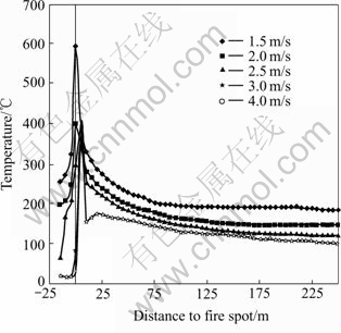
Fig.2 Longitudinal distribution of temperature at T1
From Fig.2, it can be seen that:
�� Longitudinal ventilation speed affects tempera- ture greatly, with longitudinal ventilation rate lowering the temperature increases.
�� When the longitudinal ventilation speed is lower than 3 m/s, the temperature ranges from 100 to 350 �� within 15 m upstream the fire source. This implies that hot gases still diffuses upstream the fire source. Furthermore, the diffusion velocity is higher, the depth and length of the hot smoke layer are larger with the longitudinal ventilation rate lowering, which hampers evacuation and fire fighting and rescue upstream the fire source.
�� When the longitudinal ventilation is 3 m/s or 4 m/s, the temperature ranges from 18 to 80 �� around 15 m upstream the fire source. This implies that the hot air only diffuses downstream the fire source.
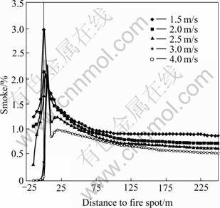
Fig.3 Longitudinal distribution of smoke concentration at T1
From Fig.3, it can be seen that:
�� The smoke distribution is similar to the temperature distribution.
�� When the longitudinal ventilation speed is lower than 3 m/s, there is smoke back layering. With longitudinal ventilation speed lowering, the smoke back layering velocity increases, and its depth and length of the smoke layer are enlarged, and affected by the action of buoyancy markedly. These hamper evacuation and fire fighting and rescue upstream the fire source.
�� When the longitudinal ventilation speed is 3 m/s or 4 m/s, smoke only flows downstream the fire source. So, the longitudinal ventilation speed is at least 3 m/s to control fire smoke back layering in Xue-feng Mountain Tunnel. Hence, the following analysis would focus on the longitudinal ventilation speed of 3.0 m/s.
2) Temperature distribution and smoke distribution at human body feature height
For the help of fire prevention and rescue, the temperature distribution and smoke concentration distribution at the body feature height level (z=1.5 m)by different longitudinal ventilation speeds are shown in Figs.4 and 5.
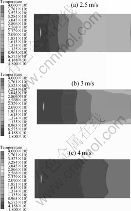
Fig.4 Temperature nephograms of body feature height level at different ventilation speeds
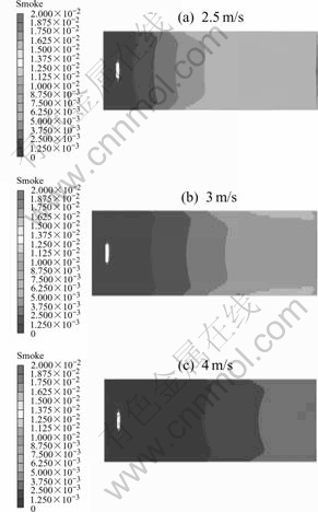
Fig.5 Smoke nephograms of body feature height level at different speeds
From Figs.4 and 5, it can be seen that:
�� The smoke distribution is similar to the temperature distribution.
�� With longitudinal ventilation speed increasing, the hot temperature layer and smoke concentration layer sink farer away from the fire source.
�� Temperature in walkways is higher than that in the middle of the road. So it is suggested that passengers should evacuate along the middle of the road in tunnel downstream the fire source.
3) Longitudinal distribution of temperature
The simulation temperature results of point T1, T2 and T3 are used to study the longitudinal distribution of the temperature in the tunnel as shown in Fig.6.
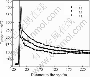
Fig.6 Longitudinal distribution of temperature at point T1, T2 and T3
From Fig.6, it can be seen that:
�� The temperature gradient is the largest nearby the fire source. The temperature is close to a constant downstream the fire source. Temperature upstream the fire keeps the initial state.
�� The highest temperature doesn��t appear above the fire source, the departure distance downstream the fire is about 5 m. This indicates that the blaze is blown away by the wind, which could avoid burning line directly.
�� The temperature of T1 at the vault downstream the fire source is the highest, T2 and T3 are lower. The temperature of T3 at the side wall downstream the fire source is higher than those of T2 and T3 .
So, it is better to evacuate along the midline of the tunnel.
4) Distribution of temperature and smoke concentration in cross section
Because of the similarity between the temperature distribution and the smoke distribution, only the temperature distribution figures are shown. The temperature nephogram of the cross section downstream the fire source at the positions of 20, 50, 125, 250 m, are shown in Figs.7(a)-(d).
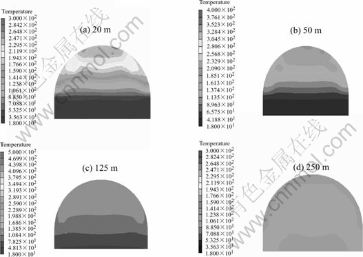
Fig.7 Temperature nephograms in different cross section positions downstream fire source
From Fig.7, it can be seen that:
�� High temperature smoke appears in layer obviously.
�� The high temperature layer is above while the low temperature layer is down downstream the fire nearby (less than 125 m). If the passage downstream the fire is close to the fire source, the passengers had better evacuate along the road rather than along the walkway which is 25 cm higher than the road surface, and its temperature is higher naturally. If the temperature at the body feature height surpasses the ultimate temperature that human can bear, passengers had better lower their height, such as bend or crawl, so as to evacuate safely.
�� The high temperature layer and low temperature layer are stagger downstream the fire (more than 125 m).Especially downstream the fire source at 250 m position (shown in Fig.7(a)), the hot temperature layer sinks and the high temperature layer appears at both side walls and at the place higher than the middle height of the tunnel. But the temperature of vault is not the highest. The passengers had better evacuate along the midline of the tunnel.
4.2.2 Transient simulation results and analysis
For the same reason that the distribution of temperature is similar to that of smoke concentration, only the temperature is analysed. The temperature variation with time of T3 point downstream the fire source at 125 m and 250 m position under different longitudinal ventilation speeds are shown in Figs.8(a) and (b).
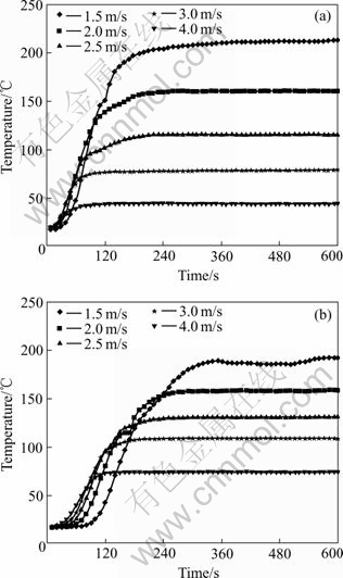
Fig.8 Temperature variations with time at 125 m position(a) and at 250 m position(b)
From Fig.8, it can be seen that:
��It takes 6 min at least for temperature to reach a constant, but with longitudinal ventilation rate increase-
ing, it takes less time.
�� The temperature changes little during the first 1 min and the temperature is nearly the natural temperature in the tunnel.
�� The temperature gradient rises between 1 min and 2 min. It also increases with the longitudinal ventilation speed increasing, and decreases in later minutes. So the first few minutes are beneficial to the evacuation.
�� Comparing Fig.8(a) with (b), the temperature of T3 downstream the fire at position 125 m is higher than that at 250 m under natural longitudinal ventilation, while it is lower under mechanical longitudinal ventilation. These indicate that the high temperature air begins to sink far away with ventilation speed increasing, and the high temperature air is still in the upper layer nearby the fire. That is also beneficial to the evacuation.
The numerical simulation results above are tallied with the data based on the similar experiments and experiences[13-16] by comparison.
5 Conclusions
1) The numerical simulation method of tunnel fire is feasible by using commercial CFD software PHOENICS3.5. It is used as a predictive means, by which some important datum and rules of smoke movement are obtained, which is impossible to obtain from the experiments.
2) With the distance upstream the fire source increasing, the temperature of winds decrease. And the temperature is reduced to a constant when the distance is large enough, so the influences scope of the high temperature is limited. The highest temperature firstly appears in side wall, and then it spreads to the middle of the tunnel with time, so it is better for the passengers to evacuate along the midline of the tunnel.
3) The longitudinal ventilation speed of 3 m/s is enough to meet the fire ventilation, which can control smoke back layering and offer air passages for the vehicles and passengers, because there is no smoke back flows under that ventilation speed.
4) The rules of smoke movement from the beginning to the growth can be obtained with transient simulation of the tunnel fire, which can offer theoretical support for the evacuation means and evacuation time.
References
[1] DU J K. Fire safety analysis of railway tunnels [J]. Safety, 1998, 19(6): 1-3.
[2] DAI G P. The analysis of england-france channel fire and its revelation [J]. Railway Construction, 2001(3): 6-9.
[3] ZENG Q L, ZHAO CH G, MEI ZH R. Study on temperature field experiment and numerical simulation during fire in tunnels [J]. Railway Journal, 1997, 19(3): 92-98.
[4] KARPOV A V, MAKAROV D V. Fire in tunnels: three�� dimensional numerical simulation and comparison with the experiment [A]. Proceedings of the 4th Asia��Oceania Symposium on Fire Science and Technology [C]. Tokyo: Waseda University, 2000: 565-576.
[5] VAUQUELIN O, MEGRET O. Smoke experiments in case of fire in a tunnel [J]. Fire Safety Journal, 2002, 37(5): 525-533.
[6] YAN Z G, YANG Q X. Study on temperature field distribution in Qinling Road Tunnel by fire experiments [J]. Underground Space, 2003, 23(2): 191-195.
[7] CAO Z M, YANG Q X. Study on Ventilation experiments of Qinling Tunnel fire[J]. Underground Space, 2003 , 23(2): 196-199.
[8] WANG M N, YANG Q X, YUAN X. Study on the temperature field during fire in road tunnels [J]. Underground Space, 2003, 23(3): 317-322.
[9] PARTANKAR S V. Numerical Calculation of Heat Transfer and Fluid Flow [M]. ZHANG Z. Beijing: Science Press, 1984. 12-19.(in Chinese)
[10] LING D, ZHOU X Q. Numerical analysis of smoke flow during mechanical smoke venting in rooms [J]. Guangzhou University Journal(natural publication), 2002, l(2): 58-60.
[11] MEGRET O, VAUQUELIN O. A model to evaluate tunnel fire characteristics [J]. Fire Safety Journal, 2000, 34(4): 391-401.
[12] LACROIX D��The new PLARC report on fife and smoke contro1 in road tunnels [A]. Third International Conference on Safety in Road and Rail Tunnels [C]. Nice, France, 1998: 185-197.
[13] ZENG Y H, HE C, GUAN B S. Study on simulation of temperature field in tunnel during fire [J]. Underground Space. 2004, 24(1): 69-71.
[14] FENG L, WANG W D, YANG Q X. Analysis on steady state of smoke in highway tunnel under fire mode [J]. Underground Space, 2004, 24(3): 359-372.
[15] XU Z S, ZH Q, XU Y. Fire model experiment and numerical simulation of passenger trains running in tunnels [J]. Journal of the China Railway Society, 2004, 26(1): 124-128.
[16] JURIJ M. Fire simulation in road tunnels [J]. Tunnelling and Underground Space Technology, 2003, 18: 525-530.
Foundation item: Project(20033179802) supported by the Science and Technology Program of China Western Transportation Development
Corresponding author: YANG Gao-shang; Tel: +86-731-8876472; E-mail: ygaoshang@mail.csu.edu.cn
Abstract: Understanding the characteristics of smoke flow in tunnel fire is very important for tunnel safety. The characteristics of tunnel fire were analyzed. The smoke development in different situations of an engineering example was simulated using commercial CFD software PHOENICS 3.5 by field modeling method. The spreading rules and characteristics of concentration field and temperature field of smoke flow with different longitudinal ventilation speeds were studied, which may provide the theoretical background for evacuation design in tunnel fire. The effective measures of fire rescue and crowd evacuation were also described.
