
����ʽ����ϵͳ���в�����̬����
����־1���»���2
(1. ���ϴ�ѧ ��Դ��ѧ�빤��ѧԺ������ ��ɳ��410075��
2. ���пƼ���ѧ ��Դ�붯������ѧԺ������ �人��430074)
ժ Ҫ��
ժ Ҫ�����ȼ�ϵ��������������������ʽ����ѭ�����������Ѹ�����, ���ö�̬�ķ���������������ʽ����ϵͳ����Ҫ�����������ڲ�ͬ��(���ݼ��ȡ���ѹ������������ȴ����ѹ����)�Ĺ������̽�����̬���̣�ͬʱ������ϵͳ����������������������Ӧ�Ķ�̬ģ�͡�������ֵ��������ѧģ�ͽ�����⣬�����������ʡ��������¶ȡ������¶ȡ������¶ȡ����书�ʵȲ�����ʱ��Ķ�̬�仯���ɡ��о���������������������������̽��е�5 minʱ�ﵽ��ֵ���������¶ȴﵽ350 K�����������ʿ�ʼ�������������¶Ƚ���315 K��Ľ������ʿ�ʼ�����������¶��ڽ����ν��е�8 minʱ����1����ֵ�������¶ȵı仯���������书�ʵı仯�����෴��
�ؼ��ʣ�
����ʽ������ ��̬����������ȼ�ϵ��������
��ͼ����ţ�TB61 ���ױ�ʶ�룺A ���±�ţ�1672-7207(2008)03-0459-05
Dynamic operating characteristics for adsorption refrigeration
YANG Pei-zhi1, CHEN Huan-xin2
(1. School of Energy Science andenergy Engineering, Central South University, Changsha 410075, China;
2. College of Energy and Power Engineering, Huazhong University of Science and Technology, Wuhan 430074, China)
Abstract: Aiming at adsorption refrigeration cycle driven by waste heat of fuel cell electrical vehicle, applied method of dynamic analysis, dynamical equations of state for adsorbent bed were built up for different phases (heating for specific volume to fix, desorbing for pressure to fix, cooling for specific volume to fix and adsorbing for pressure to fix), dynamic equations of state for evaporator and condenser were also built up. Mathematical models were solved by numerical method. The relationship between time and several parameters (adsorption rate, temperature of adsorbent bed, condensing temperature��evaporating temperature and cooling power) was discussed. The results show that adsorption rate at adsorption process reaches a peak value at 5 min, and heating rate starts reduce slowly when the temperature of adsorbent bed attains 350 K, and cooling rate starts to reduce slowly when the temperature of adsorbent bed attains 315 K. The condensing temperature in the desorption process reaches a peak value at 8 min, and the variation trend of the evaporating temperature and cooling power is reverse.
Key words: adsorption refrigeration; dynamic operating characteristics; fuel cell electrical vehicle
�����ƻ�����Դ��ȱ����ʹ����ʽ������й����ķ�չǰ��[1-3]��ȼ�ϵ��������������������ʽ��������������������������������������ܣ��Լ����ʲ���Ⱦ�������ص㣬��һ�־��з�չDZ�����������似����N. Douss��[4]���ü��ܲ���ģ�Ͷ���������ϵͳ������ģ���Ԥ�⡣A. Hajji��[5]�Դ���Ƭ�ij������������ڵĴ��ȴ��ʹ��̽���ģ�⡣�½�ƽ��[6-7]�Ի���̿-�Ҵ����������ܽ�����ʵ���о���ȼ�ϵ����������ʽ����ϵͳʵ�����й����У����������ϱ����Ⱥ���ȴ�������������¶ȵĽ���仯����֮��ƽ��������Ӱ�죬���½�����(������������)��������(����������ȴ)�IJ���[8]���Ӷ������������ɺ��������ı仯����ˣ�������ʽ����ϵͳ�ķ�������У�������̬���������Dz����ʵģ�Ҫ��ȷ�������ʽ����ϵͳ���������ԣ��ͱ�����ö�̬�ķ�������[9-11]��
1 �������Ķ�̬ģ��
Ϊ��ϵͳ��ģ�ͣ������������ڵ����������þ��ȣ����¶ȼ�ѹ������һ�£��ɲ��ü��ܲ��������з�����
��������ƽ�⣬���������½εĶ�̬���̰������ݼ��Ƚκ͵�ѹ�����Σ����������½εĶ�̬���̰���������ȴ�κ͵�ѹ������[12]��
���ݼ��ȽΣ�

��ѹ�����Σ�
������ȴ�Σ�
��ѹ�����Σ�
��ϵͳ�Ķ�̬�����У��������ƽ�����������ڶ�ϵͳ���м���ʱֻ�����¶�������������������ͬ���仯��ϵ����ʵ������ϵͳ���й����д��ڴ�����������Ȼ����������������������¶ȱ仯�ķ�ͬ�����⣬�Ӷ�����ģ���������ʵ���������ƫ ���ˣ���ϵͳ��̬ģ���У����Ƿ�ƽ�������������ʵ������������ƽ�������IJ�����Ҫ���������������ϣ��������ʷ��̿ɱ�������[13]��
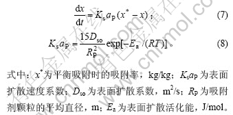
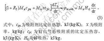
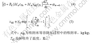
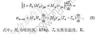
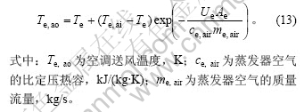
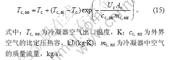
�������ڼ���(����ȴ)�������ƽ�ⷽ�̿��Ա�ʾΪ����2����ʽ��

����ʽ(9)��ʽ(10)���õ���������������������¶�֮��Ĺ�ϵΪ��
![]()
2 ���������������Ķ�̬ģ��
���������������������յ��ط������������������������������������������������������������������������������ߵ�������������������������ı仯�����������ڴ洢�������������ı仯���������������¶ȼ�ѹ�����ȣ���������ƽ�ⷽ�̣�����ʽ������

����������ʱ��û�����������������������ߵ�����ȫ����������ȴ���������������������ʡ������������ڵ��¶ȼ�ѹ�����ȣ�����������������ȫ���������ɱ���Һ�壬��������ƽ�ⷽ�̵ã�

3 ϵͳ���в����Ķ�̬�仯����
ѡȡ����������˾�������ͺ�ΪTOYOTA FCHV��һ��ȼ�ϵ�ص綯����Ϊ�о�����[14]�����������Ϊ2.5 kW��ȼ�ϵ�ز�����������80 ����ˮ����ʽ�ͷţ���������Ϊ90 kW��ѡ��Ҭ�ǻ���̿/�״����ʶ���Ϊȼ�ϵ��������������������ʽ����ϵͳ���������ʶԣ�����ʽ����ѭ����ʽ����������������ѭ��[3]�����������õ�Ԫ��������Ͻṹ��ʽ���������������������ùܴ�ʽ������������װ�ò�����ƽ��ʽ�������ͷ�[15]��
3.1 �������ʵĶ�̬�仯
ѭ������Ϊ40 min(������ȴ������20 min)ʱ�������ʶ�̬�仯�����ͼ1��ʾ���ɼ���
a. �ھ����˶��ݵĵ��ݹ����Ժ������������������Σ�������������ʱʱ���ڱ仯��
b. ������ʼ�Σ���������Ѹ��������5 min���ﵽ�˷�ֵ����������������٣�ֱ���������̽���Ϊֹ��

ͼ1 ����ϵͳ����������ʱ��Ĺ�ϵ
Fig.1 Relationship between adsorption rate and time for adsorption refrigeration
3.2 �������¶ȵĶ�̬�仯
��ϵͳ��ʵ�������У����������ϵش��ڼ�������ȴ�У�ʹ�����������¶Ȳ��ϱ仯��ѭ������Ϊ40 minʱ�������¶ȶ�̬�仯�����ͼ2��ʾ���ɼ���
a. ����������������¶Σ����������������ʺܿ죬�����������¶ȴﵽ350 Kʱ�����������������ʿ�ʼ����������Ҫ�������ڽ��������У���繩����������������Ҫ������������������Ľ������Լ�������������������ȡ��ڼ��ȳ�ʼ�Σ�û�з�������������������������ͨ���²�ݵ�����ȫ������ʹ���������¶���ߣ����������¶ȴﵽ�����¶Ⱥ�ͨ���²�ݵ��������������ṩ�����ȣ�ʣ�������������������������¶ȣ���ˣ����������������ȵ����գ����������������������ʡ�
b. ������������Ľ��¶Σ��������Ľ������ʺܿ죬�����������¶ȴﵽ315 Kʱ���������Ľ������ʿ�ʼ����������Ҫ�����������������У���ȴˮ�����������ߵ�������������������������ʱ�������������Լ�������������������ȡ�����ȴ��ʼ�Σ�û�з�����������ȴˮ��������ͨ���²�ݵ�����ȫ������ʹ���������¶Ƚ��ͣ����������¶ȴﵽ�����¶Ⱥ�ͨ���²�ݵ������������ڴ��������ȣ���ˣ����������������ȵ��ͷţ��������������Ľ������ʡ�
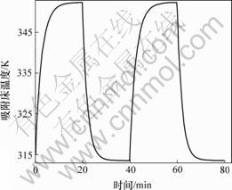
ͼ2 ����ϵͳ�������¶���ʱ��Ĺ�ϵ
Fig.2 Relationship between temperature of adsorption bed and time for adsorption refrigeration
3.3 �����¶ȵĶ�̬�仯
����ϵͳ����ʱ�����¶ȵĶ�̬�仯�����ͼ3��ʾ���ɼ�����ʼʱ��û�н������������¶������������¶Ƚӽ����ڽ�����ʼ�Σ�������Ѹ�����ӣ����������������ʽ����������ͷ��������������¶����ߣ��������̽��е�8 min���������½��������������������������½��������¶ȵ����������½�������ijһ�¶Ⱥ�����������������������һ���½�����֮��绷����������ȴ���ã�ʹ�������¶Ȼ����½����������������л�����״̬ʱ��û�н���������ʱ�����������������£���������������ȴ���ӽ������¶ȡ�
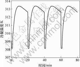
ͼ3 ����ϵͳ�����¶���ʱ��Ĺ�ϵ
Fig.3 Relationship between condensing temperature and time for adsorption refrigeration
3.4 �����¶ȵĶ�̬�仯
����ϵͳ����ʱ�����¶ȵĶ�̬�仯�����ͼ4��ʾ���ɼ��������¶ȵĶ�̬�仯�ֳ�3���Σ�
��һ������2���������л�����״̬����ʼ�Σ�����һ�Σ���������ԭ���Ľ���״̬ת��Ϊ����״̬�������������¶�û�н��͵�������ʼ�¶�ʱ��������û������������ͨ��ϵͳû�������������ʱ�����¶���������ȸ��ɵ�����������ߣ���ͼ������ab�Ρ�
�ڶ����ǵ����������¶Ƚ��͵�������ʼ�¶Ⱥ�������������ЧӦ���Ӷ����������¶ȵ��½�����������ʼ���������ϴ���ˣ������¶ȵ��½����ʽϴ����������������������������ȸ���ʱ�������¶ȼ����½���ֱ��������������ȸ�����Ȳ���ʼС������ȸ���ʱ�������¶�ֹͣ�½�����ʼ��������ͼ������bc�Ρ�
�����εĿ�ʼλ�������¶ȿ�ʼ�����ĽΣ�ֱ���������̽�����ʼ��һ��ѭ������һ�εij�����Ҫȡ���������¶ȡ���������ѭ�����ڣ���ϵͳ��ʵ�������е�����Ӧ������һЩ��

ͼ4 ����ϵͳ�����¶���ʱ��Ĺ�ϵ
Fig.4 Relationship between evaporating temperature and time for adsorption refrigeration
3.5 ���书�ʵĶ�̬�仯
����ϵͳ����ʱ���书�ʵĶ�̬�仯�����ͼ5��ʾ���ɼ������书�ʵı仯�������¶ȵı仯�����ƣ�Ҳ��Ϊ3���Σ���һ������2���������л�����״̬����ʼ�Σ���������У�������û�н����������̣�ϵͳû�������������ͼ������ab �Σ��ڶ����ǵ�����������������ͨ��ʼ�������̺���������ʼ��������Ѹ��������ˣ�ϵͳ�����书��Ҳ������ͼ������bc�Σ������εĿ�ʼλ����������ʼ�½��ĽΣ�ֱ���������̽����㿪ʼ��һ�ֵ�ѭ������ͼ������cd�Ρ�

ͼ5 ����ϵͳ���书����ʱ��Ĺ�ϵ
Fig.5 Relationship between cooling power and time for adsorption refrigeration
4 �� ��
a. ����������������ʼ��Ѹ������������5 min�ﵽ��ֵ����С��
b. �������������¶Σ��¶ȴﵽ350 Kʱ�����������������ʿ�ʼ���������������Ľ��¶Σ����¶ȴﵽ315 Kʱ���������Ľ������ʿ�ʼ������
c. �����¶��ڽ����ν��е�8 minʱ����1����ֵ��
d. �����¶ȵı仯���������Σ���һ������2���������л�����״̬����ʼ�Σ������¶������ߣ��ڶ����ǵ����������¶Ƚ��͵�������ʼ�¶Ⱥ������¶ȵ��½����ʽϴ����εĿ�ʼλ�������¶ȿ�ʼ�����ĽΣ�ֱ���������̽�����ʼ��һ�ֵ�ѭ����
e. ���书�ʵı仯ͬ������3���Σ��������������¶ȱ仯�������෴��
�ο����ף�
[1] WANG Ru-zhu, WU Jing-Yi. Performance researches and improvements on heat regenerative adsorption refrigerator and heat pump [J]. Energy Conversion and Management, 2001, 42(2): 233-249.
[2] Halder G N, Sarkar S C. Scope of carbon dioxide as a natural refrigerant for replacements of CFCs[J]. Journal of Energy in Southern Africa, 2001, 12(3): 408-411.
[3] ����־, �»���. ����ʽ����ѭ������ѧ������[J]. ���ϴ�ѧѧ��: ��Ȼ��ѧ��, 2007, 38(3): 461-467.
YANG Pei-zhi, CHEN Huan-xin. Thermodynamic analysis and performance of adsorption refrigeration loop[J]. Journal of Central South University: Science and Technology, 2007, 38(3): 461-467.
[4] Douss N, Sun L M, Meunier F. Predictive model and experimental results for a two-adsorber solid adsorption heat pump[J]. Industrial & Engineering Chemistry Research, 1988, 27(2): 310-316.
[5] Hajji A, Worek W M. Simulation of a regenerative, closed-cycle adsorption cooling/heating system[J]. Energy, 1991, 16(3): 643-654.
[6] �½�ƽ, ���۲�, ��֥��, ��. ����̿-�Ҵ�����ʽ����ϵͳ��ʵ���о�[J]. ̫����ѧ��, 1996, 17(3): 216-219.
CHEN Jiang-ping, QUE Xiong-cai, CHEN Zhi-jiu, et al. Experimental study of adsorption refrigeration system using activated carbon-ethanol pair[J]. Journal of Solar Energy, 1996, 17(3): 216-219.
[7] El-Sharkawy I I, Kuwahara K, Saha B B, et al. Experimental investigation of activated carbon fibers/ethanol pairs for adsorption cooling system application[J]. Applied Thermal Engineering, 2006, 26(8): 859-865.
[8] �� ��, ������. ��ƽ�������������������ѭ�������о�[J]. ����������ѧ��, 2001, 22(6): 674-676.
WANG Wen, WANG Ru-zhu. Investigation of solid adsorption refrigeration cycle with non-equilibrium adsorption[J]. Journal of Engineering Thermophysics, 2001, 22(6): 674-676.
[9] Restuccia G, Freni A, Vasta S, et al. Selective water sorbent for solid sorption chiller: Experimental results and modeling[J]. International Journal of Refrigeration, 2004, 27(3): 284-293.
[10] Kato Y, Sasaki Y, Yoshizawa Y. Thermal performance measurement of a packed bed reactor of a magnesium oxide/water chemical heat pump[J]. Journal of Chemical Engineering of Japan, 2003, 36(7): 833-839.
[11] Sami S M, Tribes V. An improved model for predicting the dynamic behaviour of adsorption systems[J]. Applied Thermal Engineering, 1996, 16(2): 149-161.
[12] ������, �⾲��, �����, ��. ����ʽ����[M]. ����: ��е��ҵ������, 2002.
WANG Ru-zhu, WU Jing-yi, DAI Yan-jun, et al. Adsorption refrigeration[M]. Beijing: China Machine Press, 2002.
[13] Sakoda A, Suzuki M. Simultaneous transport of heat and adsorbate in closed type adsorption cooling system utilizing solar heat[J]. Journal of Solar Energy Engineering, 1986, 108(3): 239-245.
[14] ����, �����. ȼ�ϵ�ؼ���Ӧ��[M]. ����: ���ӹ�ҵ������, 2005.
HUANG Zhen-jiang, LIU Feng-jun. Fuel cell and its application[M]. Beijing: Electronics Industry Press, 2005.
[15] ����־. ȼ�ϵ��������������������ʽ����ϵͳ�ṹ���[J]. ����, 2007, 26(2): 5-9.
YANG Pei-zhi. The design of adsorption refrigeration system driving by fuel cell electrical vehicle waste heat[J]. Refrigeration, 2007, 26(2): 5-9.
�ո����ڣ�2007-10-25�������ڣ�2008-01-16
������Ŀ��������Ȼ��ѧ����������Ŀ(50676110)������ʡ��Ȼ��ѧ����������Ŀ(04JJ3086)
ͨ�����ߣ�����־(1977-)���У���������ˣ���ʦ�����¹�������ʽ�����о����绰��13908470812��E-mail: yang_peizhi@csu.edu.cn
researches and improvements on heat regenerative adsorption refrigerator and heat pump [J]. Energy Conversion and Management, 2001, 42(2): 233-249." target="blank">[1] WANG Ru-zhu, WU Jing-Yi. Performance researches and improvements on heat regenerative adsorption refrigerator and heat pump [J]. Energy Conversion and Management, 2001, 42(2): 233-249.
[6] �½�ƽ, ���۲�, ��֥��, ��. ����̿-�Ҵ�����ʽ����ϵͳ��ʵ���о�[J]. ̫����ѧ��, 1996, 17(3): 216-219.
[8] �� ��, ������. ��ƽ�������������������ѭ�������о�[J]. ����������ѧ��, 2001, 22(6): 674-676.
�����. ȼ�ϵ�ؼ���Ӧ��[M]. ����: ���ӹ�ҵ������, 2005.
HUANG Zhen-jiang, LIU Feng-jun. Fuel cell and its application[M]. Beijing: Electronics Industry Press, 2005." target="blank">[14] ����, �����. ȼ�ϵ�ؼ���Ӧ��[M]. ����: ���ӹ�ҵ������, 2005.HUANG Zhen-jiang, LIU Feng-jun. Fuel cell and its application[M]. Beijing: Electronics Industry Press, 2005.
[15] ����־. ȼ�ϵ��������������������ʽ����ϵͳ�ṹ���[J]. ����, 2007, 26(2): 5-9.
