
Trans. Nonferrous Met. Soc. China 30(2020) 428-448
Nanomechanical properties and fracture toughness of hard ceramic layer produced by gas boriding of Inconel 600 alloy
N. MAKUCH
Institute of Materials Science and Engineering, Poznan University of Technology, Pl. M. Sklodowskiej-Curie 5, 60-965 Poznan, Poland
Received 29 April 2019; accepted 14 October 2019
Abstract:
Gas-boriding in N2-H2-BCl3 atmosphere resulted in the formation of a thick layer on Inconel 600 alloy. The microstructure of layer produced at 920 ��C for 2 h consisted of a mixture of chromium borides and nickel borides. The objective of investigations was to determine the influence of the chemical and phase compositions of borided layer on its mechanical properties. The nanoindentation was carried out using Berkovich diamond tip under a load of 50 mN. The gas-borided layer was characterized by high indentation hardness HIT from 1542.6 HV to 2228.7 HV and high elastic modulus EIT from 226.9 to 296.4 GPa. It was found that the mixture with higher percentage of chromium borides was the reason for the increase in HIT and EIT values. The fracture toughness (KC) was measured using Vickers microindentation technique under a load of 0.98 N. The presence of high compressive stresses in normal direction to the top surface caused the strong anisotropy of the borided layer, in respect of fracture toughness. The high difference between the lowest (0.5763 MPa��m1/2) and the highest (4.5794 MPa��m1/2) fracture toughness was obtained. This situation was caused by the differences in chemical and phase compositions of tested areas, presence of porosity and residual stresses. Generally, the higher KC values were obtained in areas with lower chromium content.
Key words:
gas boriding; borided layer; hardness; elastic modulus; fracture toughness;
1 Introduction
The effective improvement of hardness and wear resistance of Ni-based alloys by boriding has become a well-known and satisfactory practice, reported in many publications. Dependent on chemical composition of treated materials, boriding resulted in formation of different types of borides: nickel borides, chromium borides, iron borides or substitutional complex borides e.g. (Cr,Co)2B or (Ni,Co)2B. Generally known methods of boriding can be used for treating of Ni and its alloys: powder [1-8], paste [9], fluidized bed [10], electrochemistry [11], plasma [12], laser [13,14], and gas boriding [15-20]. Nevertheless, the commercial boriding agents containing SiC as a filler, cannot be applied for boriding of Ni-based alloys due to the simultaneous siliconizing [1-4]. During this process, a dual-layer was produced: an outer layer of porous silicides and an inner layer of borides. Therefore, some special powders without SiC were developed for boriding of Ni and its alloys [5-8]. The use of Ekabor Ni powder for boriding of pure nickel resulted in formation of thick Ni2B layers, which were characterized by improved hardness and wear resistance in comparison with substrate material [6]. Similarly, the satisfactory results were obtained in the case of boriding of Ni-based alloys. Boriding in Ekabor II powder was the reason for increase of hardness (up to HK 2400) of Incoloy 825 alloy [7]. The advantageous effects were also obtainedafter boriding using the self-protective paste [9]. As a result of this process, the thick layer (max. 75 ��m) of a high hardness (up to 2500 HV) was formed. The promising effects characterized the electro- chemical boriding process of Inconel 600 alloy [11]. Although, short process duration was used (in range from 5 to 15 min) the produced layers were characterized by high thickness of 30-80 ��m. The boride layers consisted of different types of nickel borides, and they were much harder (1600-2100 HV) than the non-borided Inconel 600 alloy substrate [11]. The gas boriding in N2-H2-BCl3 atmosphere was applied for producing of thick, hard, resistant wear layers on the surface of different Ni-based alloys: Nisil [15], Nimonic 80A [16,18,20], and Inconel 600 [17]. The measured depths of gas-borided layers were significantly increased in comparison with the layers obtained for Ni-based alloys by the pack- boriding or paste boriding process in comparable conditions of process (temperature, time).
The mechanical properties of borided layers produced on nickel and its alloys depended on following factors: chemical composition of substrate material, method of boriding and process conditions (temperature, time, boron activity). It is generally known that borided layers were characterized by high hardness, as a main advantage. On one hand, the high hardness caused increase in wear resistance of borided layer, but on the other hand high hardness strongly influenced the increased brittleness of layer. The low fracture toughness (high brittleness) could be the important factor that diminishes cohesion of layer to the substrate material or wear resistance of the layer. For this reason, the fracture toughness, as a main disadvantage of borided layer, is important information and should be studied in details.
In this study, the hard ceramic phases (nickel and chromium borides) were produced on Inconel 600 alloy using the continuous gas boriding process in N2-H2-BCl3 atmosphere. The hardness and elastic modulus were measured by using of Berkovich nanoindentation. For fracture toughness measurements the Vickers microindentation was used. The importance of phase and chemical compositions for hardness, elastic modulus and fracture toughness was analyzed. The chemical composition of tested areas was determined by using X-ray microanalyzer equipped with EDS. The objective of investigations was to determine the influence of the chemical and phase compositions of gas-borided layer on its mechanical properties.
2 Experimental
2.1 Materials
Inconel 600 alloy was used as the base material in this study. This Ni-Cr-Fe alloy is a standard engineering material for applications which require resistance to corrosion and heat. The chemical composition of Inconel 600 alloy was as follows: 15.72 wt.% Cr, 8.63 wt.% Fe, 0.18 wt.% Si, max. 0.16 wt.% Mn, 0.078 wt.% C, 0.06 wt.% Al, 0.04 wt.% Cu, <0.001 wt.% S and balance Ni. The ring-shaped specimens (external diameter 20 mm, internal diameter 12 mm and height 12 mm) were used for investigations.
2.2 Gas boriding
The gas boriding in N2-H2-BCl3 atmosphere was arranged as a continuous process at 920 ��C for 2 h. Firstly, the specimens were put into the quartz retort. Prior to heating, air was removed from the whole system by the vacuum pump. Due to the risk of oxidation of specimens, the heating process was performed in atmosphere of nitrogen with the flow rate of 150 L/h. Simultaneously, the cooling of the cylinder with boron trichloride started. During this process the cylinder with BCl3 was inserted into the cryostat. The temperature within the range from -69 to -66 ��C was obtained by using a liquid nitrogen. This low temperature ensured the appropriate concentration of boron trichloride in boriding atmosphere. The average boron trichloride concentration was equal to 5.23 vol.% in relation to H2, and 1.36 vol.% in relation to the entire atmosphere used (N2-H2-BCl3). After the furnace had reached a temperature of 920 ��C, a gas mixture of N2�CH2 was fed through the cylinder with BCl3. The continuous gas boriding was carried out for 2 h. Then, the specimens were cooled in furnace in a nitrogen atmosphere.
2.3 Phase analysis, microstructure observation and X-ray microanalysis
After gas-boriding, the samples were cut out across the produced diffusion layer. For the microstructure observation, the metallographic preparation included the following operations: grinding by using the abrasive paper of varying granularity, polishing with the application of aluminum oxide (Al2O3), and etching. In order to reveal the microstructure of borided Inconel 600 alloy, the Marble��s reagent was used. It consisted of hydrochloric acid (HCl), copper (II) sulfate (CuSO4) and distilled water (H2O). The boride layer morphology and thickness were investigated on a cross-section using a scanning electron microscope (SEM) Tescan Vega 5135. The contents of the main elements (chromium, nickel, iron and boron), occurring in the boride layer, were measured with PGT Avalon X-ray microanalyzer equipped with energy dispersive spectrometer (EDS), using 55�� take-off angle. During X-ray microanalysis, the accelerating voltage of 12 kV was used. The Si (Li) detector with ultra-thin window, standardless quantitative analysis, ZAF matrix correction algorithms for SEM bulk analysis were applied. The phase analysis of gas-borided Inconel 600 alloy was carried out by PANalytical EMPYREAN X-ray diffractometer using Cu K�� radiation. The wavelength lCu of 0.154 nm was used during investigations.
2.4 Nanoindentation procedure
The nanoindentation tests were performed on an etched cross-section of borided specimens. Based on the load�Cdisplacement curve obtained during one cycle of loading and unloading, the hardness and elastic modulus of the borided specimen were determined. The instrumented indentation tests were carried out using Anton Paar nanoindentation tester NHT2. The Berkovich indenter used for this study had an equilateral triangle as the base, and an angle of 65.3�� between the axis of the pyramid and the three faces. During the measurements the indentation load and displacement (penetration depth) were continuously recorded. The testing cycle was composed of three steps: a linear loading to the maximal load in 30 s, a 10 s holding at the maximal load of 50 mN and a linear unloading in 30 s. The maximal depth of indentation hmax was obtained for the maximal test load Fmax. Whereas the contact depth hc was the vertical distance along which the indenter had a contact with measured material. After the removal of the test load the depth of the permanent deformation in the test sample was given by permanent penetration depth hp. There were three important quantities that were determined from the load-displacement curves: the maximum load Fmax, the maximum penetration depth hmax, and the elastic unloading stiffness S defined as the slope of the upper portion of the unloading curve during the initial stage of unloading (also called the contact stiffness). The indentation parameters (hp, hmax, fitting parameter m, S) as well as the indentation hardness HIT and elastic modulus EIT were estimated from the unloading behavior according to Oliver and Pharr method [21]. The detailed methodology of nanoindentation tests and equations used for calculation of measured parameters were presented in previous work [13,22].
The microstructure of investigated layer consisted of a fine-grained mixture of nickel borides and chromium borides. Therefore, the values of Poisson ratio ��s, necessary for elastic modulus evaluation, were calculated based on previous work [13]. In this work, the indentation hardness was measured in different phases: nickel borides and chromium borides. The average hardness, measured in nickel borides, was equal to 14.87 GPa. Whereas the average hardness measured in chromium borides was equal to 31.09 GPa. Based on the obtained results, it was assumed that in the case of areas in which only nickel borides occurred (percentage of chromium borides was equal to 0), the corresponding indentation hardness was equal to 14.87 GPa. On the contrary, when indentation hardness was measured only in chromium borides (percentage of chromium borides was equal to 1), the corresponding indentation hardness was equal to 31.09 GPa. These two values were the basis of linear dependence of HIT (indentation hardness measured in gas-borided layer) on percentage of chromium borides. Therefore, the percentage of chromium borides A(CrB) and nickel borides A(NiB) in every indentation area were estimated from equations:
 (1)
(1)
 (2)
(2)
Knowing the surface percentage of mixtures of borides, it was possible to calculate the average Poisson ratio ��s for a separate indentation:
��s=A(CrB)����s(CrB)+A(NiB)����s(NiB) (3)
For calculation, the following values of Poisson ratio were taken: for chromium borides ��s(CrB)=0.22; for nickel borides ��s(NiB)=0.28 [23].
The microstructures with visible nano- indentation marks were observed using a scanning electron microscope (SEM, Tescan Vega 5135). Moreover, nickel, chromium, iron and boron concentrations in the investigated areas, in which indents were performed, were measured using the PGT Avalon X-ray microanalyzer equipped with EDS.
2.5 Fracture toughness investigation
2.5.1 Selection of cracking mode
In general, fracture toughness could be determined based on three types of cracking modes: radial-median, Palmqvist or intermediate cracks. In order to identify the type of cracking mode generated in gas-borided layer the preliminary investigations were performed. The procedure proposed in Ref. [24] was used in order to identify cracking mode. Based on this method, the cracking mode could be established by the following proportionalities:
c~P2/3 for radial-median cracking mode (4)
L~P2(1-1/n) for Palmqvist cracking mode (5)
c~P1/1.5-q(1-q/n) for intermediate cracking mode (6)
where c is the crack length from the center of the indentation to the end of the crack, L is the Vickers crack length, P is the indentation load, n is Mayer index, and q is the linear-dependence function (experimentally determined from ln c versus ln P plot).
During the preliminary investigations, the Vickers diamond indenter was used in order to generate the indentation marks with cracks. The measurements were carried out on the cross-section of specimen, and the indentation marks were generated in the middle of borided layer, in respect of its thickness. The selection of this part of layer for preliminary investigation was justified. It was related to the size of indentation marks obtained under a higher indentation load. With the use of load of 4.905 N the generated indentation marks were characterized by high diagonal��s lengths (up to 28 ��m). For this reason, on one hand, there was impossible to produce the indentation mark near the top surface. The correct procedure of hardness measurement required the keeping appropriate distance from the edge of specimen. On the other hand, the indentation mark could not be generated near the interface between the layer and the substrate material because Inconel 600 alloy was characterized by significantly lower hardness than borides, and this caused the deformation of indentation mark. For these two reasons, the measurements were carried out in the middle of the borided layer, for each indentation load used for this study.
During preliminary investigation various indentation loads (0.98, 1.96, 2.943, 3.924 and 4.905 N) were used. In order to obtain the diagrams of crack length values (c or L) versus the load (P) plotted in bi-logarithmic coordinates, the 20 measurements were carried out for each indentation load. For diagram preparation the average values of crack lengths for each indentation load were taken. OM images of the selected indentation marks with visible cracks were presented in Fig. 1.
In order to determine the cracking mode, firstly, the crack lengths from the center of the indentation to the end of the crack (c), and Vickers crack lengths (L) were measured and plotted versus the indentation load (P) in bi-logarithmic coordinates. The diagrams of crack length (c or L) versus the load (P) were plotted in bi-logarithmic coordinates (Fig. 2) in order to identify the type of cracking behavior of the gas-borided layer produced on Inconel 600 alloy. The slopes of the straight lines in the plots of ln(L or c) versus ln P were calculated for each type of cracking mode, and were presented in Fig. 2. It was found that gas-borided layer produced on Inconel 600 alloy could be represented by the radial-median cracking mode because the slopes of the straight lines in the plots of ln c versus ln P exhibited values very close to the radial- median mode regime (Eq. (4)).
2.5.2 Selection of indentation load
The selection of the indentation load used for the fracture toughness measurements requires explanation. During the preliminary investigations concerned with the selection of cracking mode, five values of indentation load were used: 0.98, 1.96, 2.943, 3.924 and 4.905 N. The load of 0.98 N was the lowest value which provided the production of cracks from indentation mark corners. When the lower indentation load was used (0.49, 0.196 and 0.098 N), the cracks, which are necessary for fracture toughness evaluation, did not appear. The highest value of indentation load was limited due to the thickness of the produced borided layers. In order to minimize the risk of influence of substrate material and specimen edge on the obtained results, the lowest value of indentation load (0.98 N) was used for KC factor calculation. This low value of indentation load made the measurements in the area near the top surface, as well as at different distances from the surface. This procedure would be impossible if higher load was used. The reason for this situation was the large size of indentation mark generated under higher load.
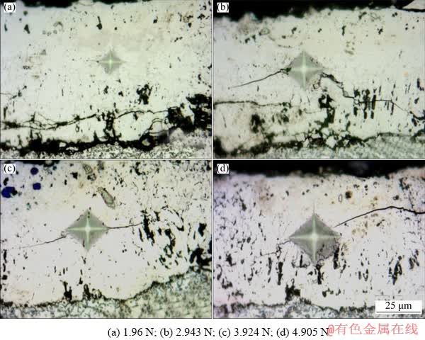
Fig. 1 OM images of Vickers indentation marks with cracks produced on gas-borided Inconel 600 alloy at different indentation loads
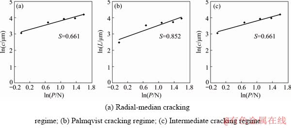
Fig. 2 Crack length criterion applied to results of boride layers formed on Inconel 600 alloy
2.5.3 Fracture toughness measurements
The fracture toughness investigations were carried out on the cross-section of a specimen using the Vickers microindentation technique. The 20 measurements of fracture toughness were performed at different distances from the surface. The microindentation was performed using the apparatus ZWICK 3212 B equipped with Vickers diamond pyramid. The indenter was used to obtain the indentation mark under a load of 0.98 N. The microcracks were generated from the corners, according to Fig. 3(b). The diagonal length 2a and the crack lengths L1, L2, L3 and L4 were immediately measured using an optical microscope. The fracture toughness was calculated based on the radial- median crack model presented in Fig. 3(a). In the case of this cracking mode, cracks are visible on the top view of the specimen, and the characteristic half-penny substructure on the cross-section occurred (Fig. 3(a)). The fracture toughness was determined based on the calculation of fracture toughness factor (KC), according to the equations:
 (7)
(7)
 (8)
(8)
where A is the residual indentation coefficient, E is the elastic modulus, and H is the hardness.

Fig. 3 Schematic views of obtained Vickers indentation marks and cracks
The average values of indentation modulus EIT, estimated using the nanoindentation technique, were taken into the calculation of fracture toughness. These values were equal to 264 GPa. The microstructures with visible indentation marks and cracks were observed using an optical microscope (OM) and a scanning electron microscope (SEM, Tescan Vega 5135). The chemical composition in tested areas was measured using the PGT Avalon X-ray microanalyzer equipped with EDS.
3 Results and discussion
3.1 Phase composition and microstructure analysis
The XRD pattern of gas-borided Inconel 600 alloy was presented in Fig. 4. XRD pattern of the borided specimen confirmed the presence of different types of nickel borides, according with Ni�CB equilibrium system: NiB, Ni2B, Ni3B, and Ni4B3. The high concentration of chromium in substrate material (15.72 wt.%) was the reason for the formation of chromium borides (CrB and Cr2B). The identified phases differed in peaks intensity. The peaks corresponding to nickel borides were predominant in the XRD patterns.

Fig. 4 XRD pattern of gas-borided Inconel 600 alloy
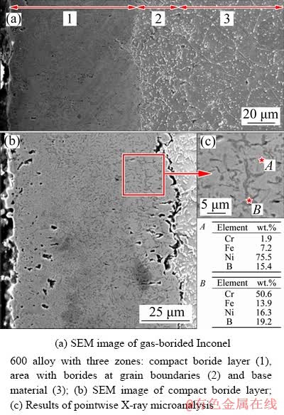
Fig. 5 Microstructures of gas-borided layer produced on Inconel 600 alloy
The microstructures of the produced gas- boride layer on Inconel 600 alloy were shown in Fig. 5 at various magnifications. The three zones were observed (Fig. 5(a)): compact boride layer (1), an area with borides at grain boundaries (2) and the base material (3). The average thickness of the compact boride layer was measured to be about 86 ��m based on SEM images. The depth of the entire diffusion layer with borides at grain boundaries was equal to about 112 ��m. The porosity of the compact boride zone was clearly visible in Fig. 5, especially in the area near the top-surface (Fig. 5(b)). According to Ref. [25], the porosity occurred as a result of corrosion due to the presence of FeCl2.
The use of higher magnifications (Figs. 5(b) and (c)) allowed to do detailed analysis of microstructure in compact boride zone. First, it was found that borides were characterized by fine-grained microstructure. The lighter and darker areas were detected. The pointwise X-ray microanalysis was performed in these two areas in order to identify which area corresponded to chromium borides, as well as nickel borides. The results obtained from the lighter area in the compact boride zone showed the increased boron and nickel concentrations as well as the relatively low chromium content (Spot A in Fig. 5(c)). That indicated the occurrence of the mixture of nickel borides in these areas. The increased chromium and boron contents, as well as low nickel content were characteristics of the darker areas (Spot B in Fig. 5(c)). It corresponded to the presence of chromium borides. Based on results of XRD analysis and pointwise X-ray microanalysis it was found that lighter areas in compact borides zone were mixture of nickel borides (NiB, Ni2B, Ni3B, and Ni4B3). Whereas, chromium borides (CrB and Cr2B) were identified as a darker areas.
Generally, the produced borided layers were characterized by strong zonation. Such a situation was observed in the case of borided layers produced on iron and steels (FeB close to the surface and Fe2B below FeB) [22,26,27], titanium alloys (TiB2 and TiB) [28,29] or cobalt alloys (CoB and Co2B) [30]. For these dual-phase layers it was easy to identify which phase occurred at the top-surface, and which phase occurred at the bottom of layer. The gas-borided layer produced on Inconel 600 alloy was characterized by multiphase fine-grained microstructure. In this type of microstructure the zonation did not appear. For this reason nickel borides and chromium borides were observed only as a mixture. Different types of borides appeared alternately on the cross-section of the whole boride layer. It was accompanied by great fluctuation of nickel and chromium concentrations through borided layer. The results of linear X-ray microanalysis presented in earlier Ref. [18] for gas-borided layer produced on Inconel 600 alloy confirmed this situation. Moreover, the increased nickel concentration usually corresponded to a diminished chromium content. In gas-borided layer produced on Inconel 600 alloy the percentage of chromium borides was not dependent on distance from the surface, therefore, it was possible to obtain higher chromium concentration at higher depth from the surface.
3.2 Nanomechanical properties
Both quantitative and qualitative information can be obtained from nanoindentation tests. For example, the comparison of load-displacement curves reveals changes in the elastic and plastic response of a system. Moreover, the presence of discontinuity in the load-displacement curve reveals information about cracking, delamination, and plasticity in the tested material. The two most commonly measured properties during an nanoindentation test are elastic modulus and hardness. Both may be measured as a function of depth of penetration into the specimen surface, thus providing a depth profile of these properties. Hardness is important since it is related in many cases to the strength or fracture toughness of materials. A high hardness generally corresponds to a high abrasive wear resistance and a high brittleness. Hardness and elastic modulus values can also be used to monitor surface or material consistency. Elastic modulus provides a measure of stiffness or compliance of the specimen. The ratio of elastic modulus to hardness (E/H) also provides valuable information about a material, since it is this ratio that determines the spatial extent of the elastic deformation that might occur under loading before permanent yielding occurs [31].
Nanomechanical properties were measured in the compact borides zone at various depths from the surface and below this zone in the base material. During an instrumented nanoindentation test the applied test load and the indentation depth of the indenter were continuously measured. The load- displacement curves, as well as the following quantities were determined: maximal penetration depth hmax, permanent penetration depth hp, hp/hmax ratio, indentation hardness HIT, indentation elastic modulus EIT. The obtained results were presented in Table 1. The five measurements were performed in compact borides zone for different distances from the surface. For base material (Inconel 600 alloy) two indentations were analyzed.
The indentation marks performed in gas- borided layer were characterized by low values of the maximal penetration depth hmax in comparison to those obtained for base material. However, some divergences between obtained indentation mark size, indentation hardness, as well as, elastic modulus were visible. The reason for differences in obtained results was the characteristic multiphase micro- structure, in which nickel borides and chromium borides appeared alternately on the cross-section of gas-borided layer. In the case of layer without zonation of phases, the indentation mark size, as well as the HIT and EIT values depended on the tested area, especially on chromium and nickel concentrations in tested area. For this reason, in Figs. 6-8, the results of X-ray microanalysis were presented. The lowest dimension of indentation mark, as well as the highest hardness was obtained for Indentation 5 (Fig. 8). It was related to the high chromium concentration in this area (28.2 wt.%). It was concluded that the obtained differences in hardness and elastic modulus are characteristic behavior for such type of microstructure. The same situation was reported in Refs. [13,16,17].
Table 1 Results of measurements using nanoindenter
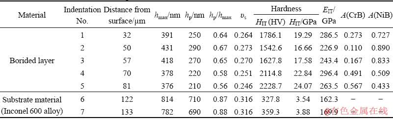

Fig. 6 Results of Nanoindentation 1 generated in compact gas-borided layer at depth of 32 ��m from surface
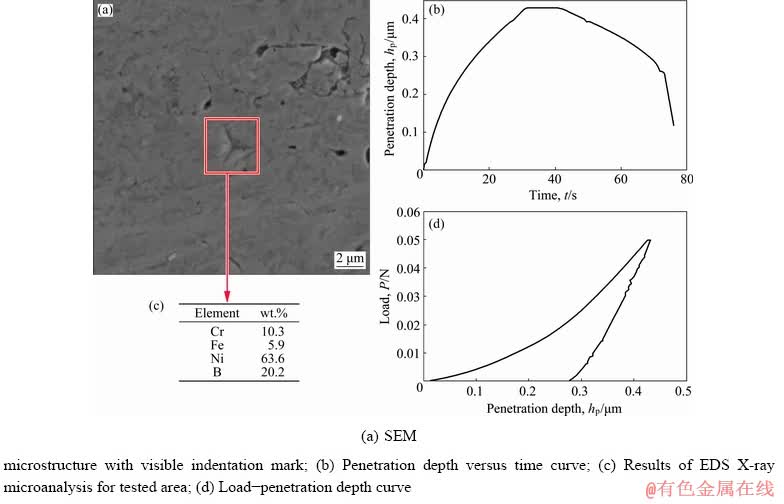
Fig. 7 Results of Nanoindentation 2 generated in compact gas-borided layer at depth of 50 ��m from surface
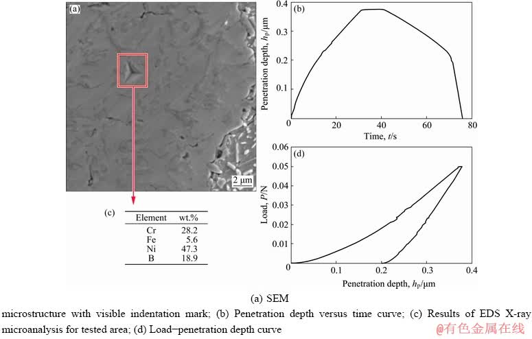
Fig. 8 Results of Nanoindentation 5 generated in compact gas-borided layer at depth of 81 ��m from surface
In the case of measurements carried out in borided layer the maximal displacement hmax was also strongly dependent on percentage of chromium borides A(CrB) in tested area. The low values of hmax were characteristics of areas in which the content of chromium borides was higher (Indentations 1, 4 and 5). Simultaneously, the permanent depth hp also decreased with the increase in the percentage of chromium borides. For Indentations 1, 4 and 5, the increased percentage of chromium borides was the reason for high indentation hardness HIT and high indentation elastic modulus EIT.
It should be noted that the differences between maximal displacement hmax and permanent displacement hp, as well as the shape of load-displacement curve indicated the type of deformation during indentation. Figures 6-8 presented experimental data for indentations made in compact borided layer at depths of 32, 50 and 81 ��m from the surface, respectively. The SEM microstructures with visible indentation marks, the penetration depths, the load-displacement curves and results of X-ray microanalysis were shown. According to Table 1, the lowest displacements hmax (376 nm) and hp (210 nm) were characteristic of Indentation 5. Therefore, this indentation mark was characterized by the lowest projected area (Fig. 8). Moreover, based on the unloading part of load-displacement curve presented in Fig. 8 the important information about the type of deformation (plastic or elastic) could be acquired. During loading stage the applied load increased up to maximal load Pmax, then during unloading stage the applied indentation load was reduced. During unloading, there was some degree of elastic recovery of the tested material as the elastically strained material outside of the plastic zone relaxed and tried to resume its original shape. As a result, the residual impression occurred on the specimen surface. On the load�Cdisplacement curve, the evidence of elastic recovery could be confirmed by a reduction in penetration depth hp with decreasing the load P. In the case of a fully elastic behavior of tested material, the unloading curve would lie on the loading curve. Whereas, for an elastic�Cplastic behavior, the loading curve differed considerably compared to the unloading curve. In this case, the area enclosed between the loading and unloading curves represented the energy lost during plastic deformation. Based on the analysis of load- displacement curves it could be concluded that Indentation 5 was characterized by more elastic behavior in comparison with other indentations. Therefore, the hardness measured at depth of 81 ��m from the surface was high (HIT=24.07 GPa). Simultaneously, for the indentation mark made at depth of 50 ��m from the surface, the highest penetration depths hmax (431 nm) and hp (290 nm) were obtained. These values, as well as the shape of loading and unloading curves (Fig. 7) indicated that this area was characterized by more plastic behavior. As a result, the calculated indentation hardness was lower (HIT=16.66 GPa).
As expected, the indentation mark made in substrate material (Fig. 9) was characterized by the highest values of penetration depths hmax and hp, 814 and 710 nm, respectively. It was clearly visible in Fig. 9 that the area between loading and unloading curves was highest (the unloading curve was almost vertical). In this case, the indenter displacement was accommodated plastically, and only its small portion was recovered on unloading curve. The position of unloading curve on load- displacement curve indicated that Inconel 600 alloy was more prone to plastic deformation. Therefore, the obtained indentation hardness HIT was low (3.54 GPa) by simultaneous relatively high elastic modulus (EIT=162.3 GPa). It was concluded that Inconel 600 alloy represents typical materials with the relatively low hardness compared to the elastic modulus, as it could be observed for a large majority of metals.

Fig. 9 Results of Nanoindentation 6 generated in substrate material (Inconel 600 alloy) at depth of 122 ��m from surface
The important measurable parameter, used in order to identify the expected behavior of tested material during indentation, could be the ratio of permanent penetration depth hp to the maximal penetration depth hmax. In the case of full elastic behavior, the hp/hmax ratio is equal to 0, whereas the obvious limit for full plastic deformation is 1. In the present study, the hp/hmax ratio was calculated and listed in Table 1. All of the indentations generated in compact borides layer were characterized by complex elastic�Cplastic behavior. However, some differences occurred. The obtained maximal displacement hmax, permanent displacement hp, as well as the hp/hmax ratio strongly depended on chromium borides percentage in tested area. The amounts of chromium and nickel borides in compact borided layer were calculated based on Eqs. (1) and (2) and were presented in Table 1. The increase in percentage of chromium borides resulted in reduced maximal and permanent penetration depths. Obviously, for indentation areas in which the higher A(CrB) was calculated (Indentations 4 and 5), the higher hardness was measured. This situation required detailed explanation. Because of fine-grained microstructure of gas-borided layer produced on Inconel 600 alloy it was difficult to measure the nanomechanical properties only in the mixture of chromium borides or nickel borides. Therefore, the literature data analysis was performed. The hardness and elastic modulus were analyzed based on literatures and presented in Table 2. The production of chromium borides by using different methods was the reason for obtaining high divergences in reported hardness and elastic modulus. The synthetization at high pressure and temperature by a solid state reaction of chromium and boron powders (Cr/B molar ratio= 1:4.5) resulted in formation of chromium borides CrB2 and CrB4 [32]. The obtained phases were characterized by high Vickers hardness in range of 15.8-23.1 GPa for CrB2 and 28.6-44.0 GPa for CrB4. The increase in indentation load (from 0.49 to 4.9 N) caused reduced hardness. In Ref. [33] the single crystals of CrB, Cr3B4, Cr2B3, and CrB2 were grown from high-temperature aluminum solutions. Each phase was characterized by similar Vickers hardness of 21.1-22.4 GPa. The CrB phase could be synthesized as a consequence of R.F. plasma- assisted magnetron sputtering method [34]. The produced thin film was characterized by low depth of 500 nm and therefore for hardness measurements the Berkovich indenter under a low load of 0.5-3 mN was used. The high hardness in range from 22.0 to 23.5 GPa was obtained. In Ref. [35] the chromium boride coating was deposited by the pulsed magnetron sputtering of loosely packed blended powder targets. Sputtering of a target having Cr/B molar ratio of 1:2 produced CrB0.92 films. Additional boron incorporated into the target, enabled the deposition of crystalline films with the CrB2 phase. The hardness and elastic modulus of the stoichiometric pulsed magnetron sputtered CrB2 film were ranged from 31.8-38.7 GPa and 217-240 GPa, respectively. Whereas, the CrB0.92 film was characterized by lower hardness (19.3-20.7 GPa) and elastic modulus (184-190 GPa). The empirical model could be also adopted for estimation of the mechanical properties of the equilibrium structures of the Cr-B system (Cr2B, CrB, CrB2 and CrB4) [36]. The calculations showed the high hardness of chromium borides (18.1-46.8 GPa). Similarly to the results obtained in Refs. [32,35], the highest hardness was determined for CrB4 phase. The lowest hardness was characteristic of CrB phase. However, the elastic module estimated via the Voigt-Reuss-Hill approximations were significantly higher than those reported by other literature data [35]. The different boriding techniques applied for Ni-based alloys resulted in formation of chromium borides. Surface modification of Nimonic 90 alloy using a self- protective silicon-boriding paste, caused the formation of a multi-phase layer on the alloy surface [3]. The total thickness of these layers was 40-90 ��m, depending on the process temperature and time. The hardness was measured on the cross-section of specimen and due to applying of a low indentation load (0.245 N) it was possible to evaluate a Vickers hardness in separate CrB phase (2082 HV). Similarly, in the case of paste-borided Nimonic 90 alloy the produced CrB needles was characterized by high hardness of 1700-2300 HV0.1 [9]. The analyzed elastic literature data and earlier papers concerning gas boriding of Nimonic 80A alloy [16] and laser-boriding of Inconel 600 alloy [13] indicated that chromium borides were hard ceramic phase with high elastic modulus. In the present study, the nanomechanical properties measurements were carried out for the mixture of fine-grained nickel borides (NiB, Ni2B, Ni3B, and Ni4B3) and chromium borides (CrB and Cr2B). Therefore, the obtained values of indentation hardness HIT and elastic modulus EIT were lower in comparison with those measured for separate chromium borides phase reported in literature data (Table 2). However, due to its high hardness, the presence of chromium borides phase in compact gas-borided layer caused limited penetration depth of Berkovich indenter during loading. Simultaneously, according to Refs. [13,16], the chromium borides mixture was characterized by high elastic modulus. Therefore, even small amount of these phases in borided layer influenced nanomechanical properties measured in gas-borided layer produced on Inconel 600 alloy.
Table 2 Literature data comparison of phase composition, hardness and elastic modulus of nickel borides and chromium borides produced by using different methods

The presence of hard and rigid chromium borides caused that tested material had a higher resistance to deformation under loading. On the other hand, the higher percentage of nickel borides in layer caused lower values of HIT and EIT in the case of Indentations 2 and 3. This situation was caused by diminished hardness and elastic modulus of nickel borides. Of course, the type of nickel boride phase had a strong influence on the properties. It could be easily concluded from literature data (Table 2) that the presence of Ni3B4 phase in borided layer was the reason for increased hardness, e.g. in the case of electrochemical boriding of Inconel 600 alloy [11] and powder pack-boriding of Inconel 718 alloy [8]. The considerably lower hardness of 690 HV0.05 was characteristic of a mixture composed of NiB and Ni2B borides formed as a result of powder pack-boriding of Incoloy 825 alloy [7]. Unfortunately, there was no information about elastic modulus of nickel borides reported in literature data. Therefore, based on earlier work in Ref. [13] it was found that nickel borides mixture which included Ni2B and Ni3B was characterized by the lower EIT value in comparison with chromium borides mixture (CrB and Cr2B).
Based on the results presented in Table 1, it was clearly visible that the distance from the surface of tested area had no influence on HIT and EIT values measured in compact borides zone. This situation was caused by the fine-grained multi-phase microstructure of borided layer. Due to the composite microstructure and no structural zonation, the mixture of chromium borides and nickel borides was alternately located in gas-borided layer. As a result, the tested microstructure was independent of the distance of the surface. Obviously, in substrate material (below distance of 86 ��m from the surface) the lower values of HIT and EIT were calculated.
The amounts of nickel borides A(NiB) and chromium borides A(CrB) in gas-borided layer were evaluated according to Eqs. (1) and (2). Based on Ref. [13] the two limits were assumed: firstly, the tested area which only consisted of nickel borides (A(CrB)=0) was characterized by HIT= 14.87 GPa and EIT=287.91 GPa. Secondly, the tested area which only consisted of chromium borides (A(CrB)=1) was characterized by HIT= 31.09 GPa and EIT=355.11 GPa. These limiting values of hardness and elastic modulus were marked in Fig. 10 as a red square and a red circle, respectively. The results presented in Table 1, as well as the assumed limited values of HIT and EIT were presented in Fig. 10 as a function of chromium borides percentage. As expected, the increased A(CrB) resulted in the increase of indentation hardness and elastic modulus measured in gas-borided layer produced on Inconel 600 alloy. The linear dependence of the indentation hardness on the surface percentage of chromium borides mixture resulted from the made assumption. However, in comparison with values obtained for laser-borided layer produced on Inconel 600 alloy [13] the lower values of elastic modulus were obtained. Probably, the differences in phase compositions of both layers were the reason for this situation. In the present study, for calculation of the A(CrB) and A(NiB) in gas-borided layer, the earlier data obtained for laser-borided layer were taken. In both layers the same types of chromium borides were produced, whereas the differences occurred in the type of the produced nickel borides mixture. The differences in phase compositions of gas- borided and laser-borided layers, as well as the divergence between elastic modulus values calculated for gas-borided layer and laser-borided layer [13], were the reason for carrying out the X-ray microanalysis from the tested area (Figs. 6-8). The results of X-ray microanalysis from the tested indentation areas revealed some conclusions. Firstly, the highest chromium content was characteristic of Indentation 5 (Fig. 8). Secondly, the indentation mark generated at a distance of 50 ��m from the surface contained the lower amount of chromium. This information corresponded with the earlier conclusions about influence of chromium borides percentage on indentation hardness and elastic modulus.

Fig. 10 Evaluated indentation hardness HIT and elastic modulus EIT as function of chromium borides percentage
The hardness and elastic modulus strongly depend on crystal structure, strength of covalent bonds, lattice parameter and efficiency of space filling. In addition, Poisson ratio is usually considered as an important parameter to describe the degree of directionality for covalent bonding. It is found that lower value of Poisson ratio indicated the existence of strong covalent bonds. In the case of chromium borides (CrB and Cr2B) the average value of Poisson ratio was equal to 0.22, whereas nickel borides mixture (NiB, Ni2B, Ni3B, Ni4B3) was characterized by higher ��s (0.28). That indicated the higher strength of covalent bonds in chromium borides structure in comparison with those in nickel borides. The higher strength of bonds caused that during indenter impression, the crystal lattice revealed a higher resistance to plastic deformation. Therefore, higher percentage of chromium borides was the reason for lower indentation depths (hmax, hp) and higher indentation hardness HIT and elastic modulus EIT. Obviously, mechanical properties of materials are also strongly dependent on lattice imperfections (dislocations, plane defects, and point defects).
3.3 Fracture toughness
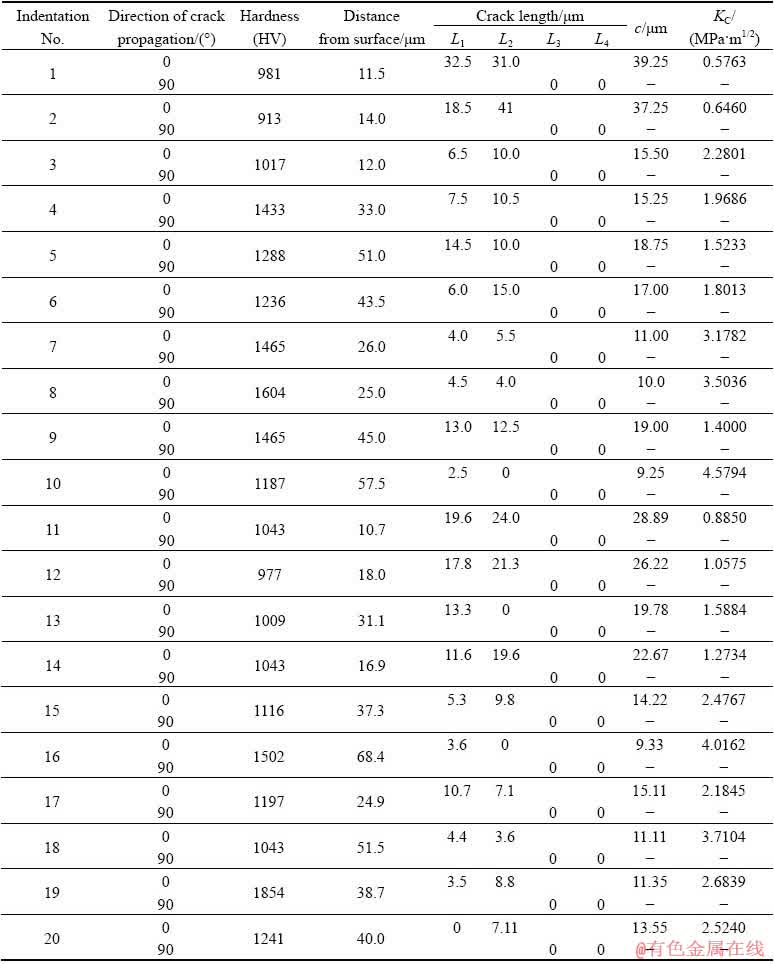
The measurements of fracture toughness were performed under a load of 0.98 N through a cross-section of the gas-borided layer produced on Inconel 600 alloy. Twenty measurements were performed at different distances from the surface. OM images of ten selected Vickers indentation marks with the generated cracks were shown in Fig. 11. Whereas, the results of measurements, i.e. Vickers hardness, distance from the surface, crack lengths from the corner of the indentation mark to the end of the crack (for direction of 0��: L1 and L2; for direction of 90��: L3 and L4), crack lengths from the center of the indentation to the end of the crack (c) and calculated fracture toughness (KC), were shown in Table 3.
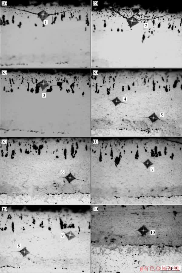
Fig. 11 OM images of ten selected Vickers indentation marks with cracks produced on gas-borided Inconel 600 alloy
In the case of the absence of the cracks from the corners (e.g. Indentation 1 for direction of 90��) the KC was not calculated, therefore in Table 3 the sign ���C�� was the attribute of the KC value for this indentation and direction of 90��. Based on the obtained results, the following general conclusions could be formulated: (1) all the cracks were generated only in the direction parallel to the top- surface of specimen (0��); (2) the obtained values of KC ranged from 0.5763 to 4.5794 MPa��m1/2; (3) fracture toughness values were strongly dependent on the tested area; (4) in general, the increase in the distance from the surface was accompanied by increase in fracture toughness.
Table 3 Vickers hardness, crack lengths from corner of indentation mark to end of crack (L1, L2, L3, L4), crack length from center of indentation mark to end of crack (c) and fracture toughness (KC) for indentations obtained in gas-borided layer produced on Inconel 600 alloy
The important information was the strong directivity of cracks generated during fracture toughness measurements under a low load of 0.98 N. This was unusual behavior. In Ref. [22] the fracture toughness of borided layers produced on Armco iron was analyzed. In the case of iron borides the cracks occurred in both parallel and perpendicular directions to the surface. Moreover, it should be noted that the crack lengths, generated in a direction parallel to the surface, were often similar to those obtained for the same indentation marks in a direction perpendicular to the surface. The differences in fracture toughness, measured in both directions (parallel and perpendicular to the surface), were slight, e.g. KC(0��)=2.07 MPa��m1/2 and KC(90��)=2.14 MPa��m1/2. In the present study, all cracks were generated only in the direction parallel to the top-surface of specimen (0��). This unusual behavior did not occur in the case of iron borides. The directivity of crack propagation from the corners of Vickers indentation marks was obtained for gas-borided layers produced on Nimonic 80A alloy [19]. In the case of Inconel 600 alloy the identical situation took place. The reason for this situation could be the presence of strong compressive stresses in the normal direction (90��) to the top-surface. The presence of high compressive stress was the reason for retardation of cracks propagation in the normal direction.
Based on the results presented in Table 3 and Fig. 11, it should be noted that high difference between the lowest (0.5763 MPa��m1/2) and the highest (4.5794 MPa��m1/2) KC values occurred. Therefore, providing the average fracture toughness of entire gas-borided layer was incorrect.
Generally, the lowest facture toughness was obtained near the top surface. For Indentation 1 (Fig. 11(a)), which was generated at the distance of 11.5 ��m from the surface, the KC was equal to 0.5763 MPa��m1/2. The long cracks (32.5 and 31 ��m) were generated from the corners in direction parallel to the top surface. Whereas, the short cracks were obtained for higher depth from the top surface. For Indentation 10 (Fig. 11(h)), which was generated at the distance of 57.5 ��m from the surface, the KC was equal to 4.5794 MPa��m1/2. Obviously, the low length of crack (L1=2.5 ��m) affected the improvement of fracture toughness.
There were several factors which caused the increase in brittleness in the region near the top-surface. Firstly, the microstructural defects such as the presence of pores (Figs. 5(b) and 11(a-c)) in the gas-borided layer produced on Inconel 600 alloy lead to stress concentration around them. When the layer is subjected to the applied load, in order to release energy, in some regions with high stress cracking appears. Furthermore, failure anisotropy may operate within the layers, in addition to residual stresses [37]. Simultaneously, the obtained differences in KC values may be caused by the presence of different phases in the borided layer (various types of nickel and chromium borides). The brittleness of the boride layer could be associated with the presence of multiphase structure. Firstly, the produced phases and substrate material differed in crystal structure: orthorhombic (Ni3B, Ni4B3, NiB, CrB), tetragonal (Cr2B, Ni2B), and cubic (Ni). Secondly, they were characterized by different values of thermal expansion coefficient, e.g. Ni2B (7.64��10-6/��C), Ni3B (7.9��10-6/��C), and Cr2B (11.1��10-6/��C). In contrast, the thermal expansion coefficient of substrate material (Inconel 600 alloy) is equal to 11.4��10-6/��C. After gas boriding process finished, the samples were cooled in nitrogen atmosphere. During cooling the distribution of the thermal expansion coefficients created compressive stress in the vicinity of the interface between nickel borides mixture and chromium borides mixture. In addition, the tensile stress around the interface between the boride layer and substrate material could occur. Moreover, during boriding, microstructure transforms to various nickel and chromium borides with different crystallographic orientations, crystal structures, and proportions. It is obvious that the layer is durable when the atoms are oriented in the same direction and build up in the same crystal network. Deviation from the textural frame decreases the mechanical strength of the multiple boride phases due to the lattice strains when formed together. Therefore, cracking occurred, as there are internal stresses between different types of boride phases [38].
In general, the increase in the distance from the surface was accompanied by the increase in fracture toughness. However, there was some deviating from this rule. The decrease in fracture toughness obtained at distance of 45-50 ��m from the top-surface was clearly visible in Table 3. The reason for KC diminishing was the characteristic multiphase fine-grained microstructure of gas- borided layer, which does not reveal the zonation. The absence of zonation of phases in borided layer produced on Inconel 600 alloy caused that the percentages of chromium and nickel borides in layer were independent of the distance from the surface. Therefore, the calculated values of KC were lower for Indentations 5 and 9 presented in Table 3.
The multicomponent fine-grained micro- structure in which fluctuation in phase composition occurred, caused differences in hardness and fracture toughness. It should be also noticed that the obtained dimensions of indentation size, as well as the cracks lengths differed even when the measurements were carried out at the same distance from the surface. For example, Indentation 5 (Table 3) was produced at a distance of 51.0 ��m from the surface and was characterized by longer crack lengths and also lower KC value in comparison with Indentation 18 (Table 3) which was generated at the same distance from the surface. For Indentation 18, the crack lengths were three time shorter than those obtained for Indentation 5. This result indicated that the crack lengths and fracture toughness differed significantly, even if measurements were carried out at the same distance from the surface.
Based on results presented in Table 3 and Fig. 11, it was clearly seen that the indentation size, as well as hardness value differed significantly, although the same indentation load was used. In the case of multicomponent diffusion layers the differences in hardness on the cross-section of layer were often observed. They could be several factors that caused fluctuation in indentation marks size, as well as in hardness values. The produced gas- borided layer on Inconel 600 alloy was characterized by multiphase fine-grained micro- structure without zonation in which the mixture of nickel borides and chromium borides occurred. Therefore, in this type of microstructure nickel borides (NiB, Ni2B, Ni3B, and Ni4B3) and chromium borides (CrB and Cr2B) were observed only as a mixture. Different types of borides appeared alternately on the cross-section of the whole boride layer. It was accompanied by great fluctuations of nickel and chromium concentrations through the borided layer. It was obvious that higher percentage of chromium borides caused small indentation mark size and simultaneously higher hardness. Obviously, in areas in which nickel borides were predominant phases in layer, lower hardness was obtained because of higher dimensions of indentation mark size. In gas-borided layer produced on Inconel 600 alloy, the occurrence of each phase was independent of distance from the surface. This fluctuation in phase concentration on the cross-section of layer strongly influenced the hardness values. Therefore, there was possibility to obtain differences in indentation mark size, as well as in hardness, even when measurements were carried out at the same distance from the surface.
In Ref. [19], the high brittleness of gas-borided layer produced on Nimonic 80A alloy was accompanied by the increased chromium borides mixture percentage. In order to confirm this thesis suitable for the case of gas-borided layer produced on Inconel 600 alloy, the EDS analysis of two selected indentation marks was performed. The contents of the main elements (chromium, nickel, iron and boron), occurring in the boride layer, were measured. The X-ray microanalysis by EDS was performed for the areas in which Vickers indentation marks were generated. In Fig. 12(a), the indentation performed at distance of 38.7 ��m from the surface was presented. This was numbered in Table 3 as Indentation 19. Whereas, in Fig. 12(b) the indentation numbered as 16 in Table 3 was shown. It was found that the crack lengths were higher in the case of Indentation 19, therefore the lower value of KC was obtained (2.6839 MPa��m1/2). The diminished fracture toughness value was accompanied by higher chromium concentration in this area. Simultaneously, for Indentation 16 (Fig. 12(b)) the EDS analysis results indicated lower chromium concentration. Hence, the higher fracture toughness (KC=4.0162 MPa��m1/2) was obtained in this case.

Fig. 12 SEM images and results of EDS X-ray microanalysis of Vickers indentation marks with cracks produced on gas-borided Inconel 600 alloy
The percentage of chromium borides in tested area strongly influenced fracture toughness. The decreased fracture toughness in areas with higher concentration of chromium borides was related to the mechanical properties. Chromium borides are characterized by higher hardness and elastic modulus in comparison with nickel borides. The high stiffness of chromium boride showed that this phase is not prone to plastic deformation during indentation. For this reason during Vickers hardness test, when indenter encountered chromium borides, the cracking energy was not transformed to plastic deformation. As a result, the cracks were propagated into higher distances from the corners of indentation marks. Such a situation caused the decrease in fracture toughness measured in the area with higher chromium borides contents.
4 Conclusions
(1) The method of gas-boriding in N2-H2- BCl3 atmosphere was used for production of the multi-phase layer on Inconel 600 alloy substrate. Three zones were observed in a microstructure of gas-borided Inconel 600 alloy: compact boride layer, an area with borides at grain boundaries and the base material.
(2) The gas-borided layer was characterized by high indentation hardness (HIT from 1542.6 HV to 2228.7 HV and high elastic modulus (EIT from 226.9 to 296.4 GPa). It was found that the higher values of HIT and EIT were measured in areas with higher chromium percentage.
(3) The hardness and elastic modulus were independent of the distance from the surface. This situation resulted from the characteristic fine- grained microstructure of gas-borided layers produced on Inconel 600 alloy. Moreover, the produced layer consisted of different types of nickel and chromium borides alternately located in the cross-section of layer without zonation.
(4) The gas-borided layer represented the group of materials with both plastic and elastic behaviors. For borides mixture with higher chromium borides percentage the results indicated the more elastic behavior in comparison with areas in which nickel borides were predominant.
(5) Due to the presence of high compressive stresses in normal direction (90��) to the top surface, strong anisotropy of the borided layer, in respect of fracture toughness, was obtained. All the cracks were generated only in the direction parallel to the top surface of specimen (0��).
(6) The fracture toughness values were independent of the measured distance from the surface. However, the lowest value of KC was obtained below the top surface, due to high porosity and residual stress presence in this area. High fracture toughness was accompanied by lower concentration of chromium in the investigated area.
Acknowledgments
This work has been financially supported by Ministry of Science and Higher Education in Poland as a part of the ��02/24/DSPB�� Project. The author wishes to thank Prof. M. Kulka and Ph.D. A. Piasecki from Institute of Materials Science and Engineering for their help and cooperation during the realization of this work.
References
[1] OZBEK I, AKBULUT H, ZEYTIN S, BINDAL C, UCISIK A H. The characterization of borided 99.5% purity nickel [J]. Surface and Coatings Technology, 2000, 126: 166-170.
[2] MUHAMMAD W, HUSSAIN K, TAUQIR A, ULHAQ A, KHAN A Q. Evaluation of halide-activated pack boriding of INCONEL 722 [J]. Metallurgical and Materials Transactions A, 1999, 30: 670-675.
[3] LOU D C, AKSELSEN O M, SOLBERG J K, ONSOIEN M I, BERGET J, DAHL N. Silicon-boronising of Nimonic 90 superalloy [J]. Surface and Coatings Technology, 2006, 200: 3582-3589.
[4] MU D, SHEN B, YANG C, ZHAO X. Microstructure analysis of boronized pure nickel using boronizing powders with SiC as diluents [J]. Vacuum, 2009, 83: 1481-1484.
[5] GUNES I, KAYALI Y. Investigation of mechanical properties of borided Nickel 201 alloy [J]. Materials and Design, 2014, 53: 577-580.
[6] UEDA N, MIZUKOSHI T, DEMIZU K, SONE T, IKENAGA A, KAWAMOTO M. Boriding of nickel by the powder-pack method [J]. Surface and Coatings Technology, 2000, 126: 25-30.
[7] AYTEKIN H, AKCIN Y. Characterization of borided Incoloy 825 alloy [J]. Materials and Design, 2013, 50: 515-521.
[8] PETROVA R S, SUWATTANANONT N, SAMARDZIC V. The effect of boronizing on metallic alloys for automotive applications [J]. Journal of Materials Engineering and Performance, 2008, 17: 340-345.
[9] LOU D C, SOLBERG J K. AKSELSEN O M, DAHL N. Microstructure and property investigation of paste boronized pure nickel and Nimonic 90 superalloy [J]. Materials Chemistry and Physics, 2009, 115: 239-244.
[10] ANTHYMIDIS K G, ZINOVIADIS P, ROUSSOS D, TISPAS D N. Boriding of nickel in a fluidized bed reactor [J]. Materials Research Bulletin, 2002, 3: 515-522.
[11] SISTA V, KAHVECIOGLU O, KARTAL G, ZENG Q Z, KIM J H, ERYILMAZ O L, ERDEMIR A. Evaluation of electrochemical boriding of Inconel 600 [J]. Surface and Coatings Technology, 2013, 215: 452-459.
[12] HUNGER H J, LOBIG G. Generation of boride layers on steel and nickel alloys by plasma activation of boron trifluoride [J]. Thin Solid Films, 1997, 310: 244-250.
[13] KULKA M, MAKUCH N, DZIARSKI P, PIASECKI A. A study of nanoindentation for mechanical characterization of chromium and nickel borides�� mixtures formed by laser boriding [J]. Ceramics International, 2014, 40: 6083-6094.
[14] MAKUCH N, DZIARSKI P, KULKA M, PIASECKI A, TULINSKI M, MAJCHROWSKI R. Influence of niobium and molybdenum addition on microstructure and wear behavior of laser-borided layers produced on Nimonic 80A alloy [J]. Transactions of Nonferrous Metals Society of China, 2019, 29(2): 322-337.
[15] KULKA M, MAKUCH N, POPLAWSKI M. Two-stage gas boriding of Nisil in N2-H2-BCl3 atmosphere [J]. Surface and Coatings Technology, 2014, 244: 78-86.
[16] MAKUCH N, KULKA M, PACZKOWSKA M. Nanomechanical properties of gas-borided layer produced on Nimonic 80A alloy [J]. Ceramics International, 2017, 43: 8255-8261.
[17] MAKUCH N, KULKA M. Microstructural characterization and some mechanical properties of gas-borided Inconel 600-alloy [J]. Applied Surface Science, 2014, 314: 1007-1018.
[18] MAKUCH N, KULKA M, PIASECKI A. The effects of chemical composition of Nimonic 80A-alloy on the microstructure and properties of gas-borided layer [J]. Surface and Coatings Technology, 2015, 276: 440-455.
[19] MAKUCH N, KULKA M. Fracture toughness of hard ceramic phases produced on Nimonic 80A-alloy by gas boriding [J]. Ceramics International, 2016, 42: 3275-3289.
[20] MAKUCH N, KULKA M, MIKOLAJCZAK D. Corrosion behavior of hard boride layer produced on Nimonic 80A-alloy by gas boriding [J]. Transactions of the Indian Institute of Metals, 2017, 70(10): 2509-2527.
[21] OLIVER W C, PHARR G M. An improved technique for determining hardness and elastic modulus using load and displacement sensing indentation experiments [J]. Journal of Materials Research, 1992, 7(6): 1564-1583.
[22] KULKA M, MAKUCH N, PIASECKI A. Nanomechanical characterization and fracture toughness of FeB and Fe2B iron borides produced by gas boriding of Armco iron [J]. Surface and Coatings Technology, 2017, 325: 515-532.
[23] LIANG Y, ZHONG Z, ZHANG W. A thermodynamic criterion for designing superhard transition-metal borides with ultimate boron content [J]. Computional Matererial Science, 2013, 68: 222-228.
[24] CAMPOS-SILVA I, FLORES-JIMENEZ M, RODRIGUEZ- CASTRO G, HERNANDEZ-SANCHEZ E, MARTINEZ- TRINIDAD J, TADEO-ROSAS R. Improved fracture toughness of boride coating developed with a diffusion annealing process [J]. Surface and Coatings Technology, 2013, 237: 429-439.
[25] HEGEWALDT F, SINGHEISER L, TUERK M. Gasborieren [J]. Hardening Technical Informations, 1984, 39: 7-15.
[26] TAKTAK S. Some mechanical properties of borided AISI H13 and 304 steels [J]. Materials and Design, 2007, 28: 1836-1843.
[27] KAYALI Y, TAKTAK S. Characterization and Rockwell-C adhesion properties of chromium-based borided steels [J]. Journal of Adhesion Science and Technology, 2015, 29: 2065-2075.
[28] KARTAL G, TIMUR S. Growth kinetics of titanium borides produced by CRTD-Bor method [J]. Surface and Coatings Technology, 2013, 215: 440-446.
[29] MAKUCH N, KULKA M, KEDDAM M, TAKTAK S, ATAIBIS V, DZIARSKI P. Growth kinetics and some mechanical properties of two-phase boride layers produced on commercially pure titanium during plasma paste boriding [J]. Thin Solid Films, 2017, 626: 25-37.
[30] RODRIGUEZ-CASTRO G A, RESENDIZ-CALDERON C D, JIMENEZ-TINOCO L F, MENESES-AMADOR A, GALLARDO-HERNANDEZ E A, CAMPOS-SILVA I E. Micro-abrasive wear resistance of CoB/Co2B coatings formed in CoCrMo alloy [J]. Surface and Coatings Technology, 2015, 284: 258-263.
[31] FISCHER-CRIPPS A C. Nanoindentation [M]. New York: Springer, 2002.
[32] WANG S, YU X, ZHANG J, ZHANG Y, WANG L, LEINENWEBER K, XU H, POPOV D, PARK C, YANG W, HE F D, ZHAO Y. Crystal structures, elastic properties, and hardness of high pressure synthesized CrB2 and CrB4 [J]. Journal of Superhard Materials, 2014, 36(4): 279-287.
[33] OKADA S, KUDOU K, IIZUMI K, KUDAKA K, HIGASHI I, LUNDSTROM T. Single-crystal growth and properties of CrB, Cr3B4, Cr2B3 and CrB2 from high-temperature aluminum solutions [J]. Journal of Crystal Growth, 1996, 166: 429-435.
[34] ZHOU M, NOSE M, MAKINO Y, NOGI K. Annealing effects on the structure and mechanical properties of r.f.-sputtered Cr-B hard thin films [J]. Thin Solid Films, 2000, 359: 165-170.
[35] AUDRONIS M, KELLY P J, ARNELL R D, VALIULIS A V. Pulsed magnetron sputtering of chromium boride films from loose powder targets [J]. Surface and Coatings Technology, 2006, 200: 4166-4173.
[36] ZHONG M M, HUANG C, TIAN C L. The structural stabilities, mechanical properties and hardness of chromium tetraboride: Compared with low-B borides [J]. International Journal of Modern Physics B, 2016, 30: 165-201.
[37] RODRIGUEZ-CASTRO G, CAMPOS-SILVA I, CHAVEZ- GUTIERREZ E, MARTINEZ-TRINIDAD J, HERNANDEZ- SANCHEZ E, TORRES-HERNANDEZ A. Mechanical properties of FeB and Fe2B layers estimated by Berkovich nanoindentation on tool borided steel [J]. Surface and Coatings Technology, 2013, 215: 291-299.
[38] KELLY A, KNOWLES K M. Crystallography and crystal defects [M]. 2nd. New York: John Wiley and Sons, 2012.
Inconel 600�Ͻ����������Ʊ�Ӳ���մɲ��������ѧ���ܺͶ�������
N. MAKUCH
Institute of Materials Science and Engineering, Poznan University of Technology, Pl. M. Sklodowskiej-Curie 5, 60-965 Poznan, Poland
ժ Ҫ����������������Inconel600�Ͻ������N2-H2-BCl3�������Ʊ��մ�Ϳ�㡣��920 ��C��2 h ����������Ϳ�������֯�к����������������о���Ļ�ѧ�ɷֺ�����ɶ�����ѧ���ܵ�Ӱ�졣����Berkovich ���ʯ�����غ�Ϊ50 mN�������½�������ѹ�۲��ԡ�����������������нϸߵ�����ѹ��Ӳ�� (HIT: 1542.6 HV~2228.7 HV)�͵���ģ��(EIT: 226.9~296.4 GPa)��HIT��EITֵ������������������������ı����ϸߡ�����ά��ѹ�ۼ����ⶨ��0.98 N�غ��µĶ�������KC�������ʾ�����淨���ѹӦ���Ĵ��ڵ���������ڶ������Է�����к�ǿ�ĸ������ԣ�������Ͷ�������ֵ(0.5763 MPa��m1/2)����߶�������ֵ(4.5794 MPa��m1/2)֮����ڽϴ���졣������������ԭ���Dz�������Ļ�ѧ�ɷ֡�����ɡ���϶�ȺͲ���Ӧ�����ڲ��졣һ����˵���������ϵ͵������������KCֵ�ϴ�
�ؼ��ʣ����������㣻Ӳ�ȣ�����ģ������������
(Edited by Wei-ping CHEN)
Corresponding author: N. MAKUCH; E-mail: natalia.makuch@put.poznan.pl
DOI: 10.1016/S1003-6326(20)65224-4
Abstract: Gas-boriding in N2-H2-BCl3 atmosphere resulted in the formation of a thick layer on Inconel 600 alloy. The microstructure of layer produced at 920 ��C for 2 h consisted of a mixture of chromium borides and nickel borides. The objective of investigations was to determine the influence of the chemical and phase compositions of borided layer on its mechanical properties. The nanoindentation was carried out using Berkovich diamond tip under a load of 50 mN. The gas-borided layer was characterized by high indentation hardness HIT from 1542.6 HV to 2228.7 HV and high elastic modulus EIT from 226.9 to 296.4 GPa. It was found that the mixture with higher percentage of chromium borides was the reason for the increase in HIT and EIT values. The fracture toughness (KC) was measured using Vickers microindentation technique under a load of 0.98 N. The presence of high compressive stresses in normal direction to the top surface caused the strong anisotropy of the borided layer, in respect of fracture toughness. The high difference between the lowest (0.5763 MPa��m1/2) and the highest (4.5794 MPa��m1/2) fracture toughness was obtained. This situation was caused by the differences in chemical and phase compositions of tested areas, presence of porosity and residual stresses. Generally, the higher KC values were obtained in areas with lower chromium content.
