
Trans. Nonferrous Met. Soc. China 25(2015) 3389-3398
Modified MK model combined with ductile fracture criterion and its application in warm hydroforming
Xi-ying YANG, Li-hui LANG, Kang-ning LIU, Chan GUO
School of Mechanical Engineering and Automation, Beihang University, Beijing 100191, China
Received 17 November 2014; accepted 30 January 2015
Abstract:
A modified MK model combined with ductile fracture criterion (DFC-MK model) is proposed to compute the forming limit diagrams (FLDs) of 5A06-O aluminum alloy sheet at different temperatures. The material constant (C) of ductile fracture criterion and initial thickness imperfection parameter (f0) at various temperatures are determined by using a new computing method based on wide sheet bending test. The FLDs at 20 and 200 ��C are calculated through the DFC-MK model. The DFC-MK model, which includes the influence of through-thickness normal stress, is written into the subroutine VUMAT embedded in Abaqus/ Explicit. The cylindrical cup hydroforming tests are carried out to verify the model. The results show that compared with experimental observations, the predicted FLDs based on DFC-MK model are more accurate than the conventional MK model; the errors between the simulations and experiments in warm hydroforming are 8.23% at 20 ��C and 9.24% at 200 ��C, which verify the effectiveness of the proposed model.
Key words:
MK model; ductile fracture criteria; warm hydroforming; through-thickness normal stress;
1 Introduction
The forming limit of sheet metals is an important process parameter and the main basis for mould design and process optimizing in aircraft part forming. Many theoretical research results [1,2] on the forming limit have been in application, which are obtained by using macroscopic continuum mechanics and microscopic damage mechanics, separately. HILL [2] assumed that localized instability only occurs in case that the ratio of the minor strain to the major strain is less than or equal to zero. However, a series of experiments proved that localized instability can also occur when the ratio is larger than zero [3]. To explain the difference between the Hill��s theory and experimental observations in predicting the right-hand curve of FLD, MARCINIAK and KUCZYNSKI [4] proposed an MK model in which the initial thickness imperfection such as a geometric groove in the sheet metal is assumed to exist and generates plastic instability. There is an obvious discrepancy between the predictive forming limit curve and experimental observations by using different initial thickness imperfections which are difficult to be determined [5].
Recently, researchers have introduced ductile fracture criteria [6,7] into the field of sheet metal forming, such as hydroforming [8], bore expansion [9], tube bending [10] and biaxial stretching [11]. Some problems also appear in these applications [12]. Ductile fracture criteria can effectively predict the occurrence of fracture. However, the forming limit diagram at fracture (FLDF) determined by ductile fracture criterion is higher than FLD and more serious in predicting sheet metal forming. Therefore, the limitation of ductile fracture criteria exists in the field of sheet metal forming [13]. The acquisition of material constant is a critical point in application of ductile fracture criteria. Currently, two methods have been used in literatures: numerical calculation method [14] which is simple, however, not in accord with the experimental observations, and finite element analysis (FEA) combined with simple experiment [15] which needs many complicated adjustments to operate.
In the actual process, such as sheet hydroforming, the blank undergoes through-thickness normal stress induced by fluid pressure. BANABIC and SOARE [16] used the MK model to research the effect of fluid pressure on forming limit of AA3104-H19 sheet, where the range of fluid pressure varied from 0 to 200 MPa. The results presented that fluid pressure improved formability. NURCHESHMEH and DANIEL [17] extended the MK model to take the influence of through-thickness normal stress into account. It is observed that the forming limit increases with greater through-thickness normal stress. The conclusion from NURCHESHMEH and GREEN [18] is drawn that the prediction of forming limit will not be accurate enough regardless of the three-dimensional stress state.
In the present study, to compute the FLDs of 5A06-O aluminum alloy sheet at different temperatures, a modified MK model combined with ductile fracture criteria is proposed. The material constants of different ductile fracture criteria and the initial thickness imperfection parameter at various temperatures are calculated by using a new computing method based on wide sheet bending. The validity of the DFC-MK model is examined by comparing with experimental results and the conventional MK model at 20 and 200 ��C. The DFC-MK model, which includes the influence of through-thickness normal stress, is written into the subroutine VUMAT embedded in Abaqus/Explicit. Finally, the cylindrical cup hydroforming tests at 20 and 200 ��C are carried out to verify the DFC-MK model.
2 Theory of DFC-MK model
2.1 Classical ductile fracture criteria
Based on various hypotheses, many ductile fracture criteria have been proposed. The following criteria are widely used in the field of sheet metal forming. Material constants will be changed into absolute value to ensure the computing procedures in the present study.
Clift criterion [19]:
 (1)
(1)
Cockcroft and Latham [20]:
 (2)
(2)
Brozzo criterion [19]:
 (3)
(3)
Oyane et al [21]:
 (4)
(4)
where  is the equivalent plastic strain,
  is the equivalent plastic strain at fracture,
  is the equivalent stress, ��* is the maximum principal stress, ��h is the hydrostatic pressure, and C1-C5 are material constants.
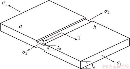
Fig. 1 Schematic diagram of conventional MK model
2.2 DFC-MK model
In the conventional MK model, the initial thickness imperfection parameter (f0) such as a geometric groove in sheet metal is assumed to exist and generates plastic instability (see Fig. 1). This model has been generally used to predict the FLDs of sheet metal in the plane stress state and has the following hypotheses [4]:
1) The safe zone a is subjected to the proportional loading.
2) The strain increments in the safe zone a and groove zone b in direction 2 are equal (d��2,a=d��2,b=d��2).
3) The forces per unit sheet width of both zones in direction 1 are equal (F1,a=F1,b).
In order to consider normal anisotropy of the sheet metal, the effective stress is defined by Hill��48 yield criterion [22] as
 (5)
(5)
where ��1, ��2 and ��3 are the first, second and third stresses, respectively, and r is the normal anisotropy coefficient (the ratio of transverse strain to through-thickness normal strain). In this work, a modified MK model based on ductile fracture criteria (DFC-MK model) is proposed. In the DFC-MK model, the ductile fracture criterion is the failure criterion of zone b. The strains in zone a are defined as the forming limit point. The computing procedure is shown as follows.
Under the plane stress condition, the relations in Eq. (5) can be simplified as
 (6)
(6)
where �� is the principal stress ratio, namely, ��=��2/��1 (0 �� �� ��1), G1 is defined as the relation: G1=2r/(1+r). The Levy-Mises relation formula is shown as
 (7)
(7)
where �� is the ratio of equivalent stress to the major principal stress, namely, ��=��/��1=(1+��2-G1��)1/2. d��1, d��2 and d��3 are the principal strain increments, and  is the equivalent strain increment.
 (8)
(8)
 (9)
(9)
From hypotheses (3) in Section 2.2, the equation can be obtained, that is,
 (10)
(10)
where ta and tb are the thicknesses of zones a and b, respectively. The initial thickness imperfection parameter is defined as f0, namely, f0=tb0/ta0. Therefore, the subsequent thickness imperfection parameter can be expressed as
 (11)
(11)
To unify the analytical form, the plastic behavior of 5A06-O aluminum alloy at room temperature has been fitted using a Swift��s power law:
 (12)
(12)
where K is the strength coefficient, n is the strain hardening exponent, and m is the strain rate sensitivity exponent.
In the forming temperature range of 150-300 ��C, the coefficients are related to temperature. The relationships between the coefficients and temperature are fitted, that is,
 (13)
(13)
where t is temperature. The equilibrium equation can be derived by using Eqs. (10)-(13). The result is expressed as

 (14)
(14)
Equation (14) is computed by using the Newton- Raphson iteration method. When the cumulative plastic work in zone b reaches a certain critical value, namely, , the strain value in zone a is the forming limit point. By changing �� in the range of 0 to 1, the forming limit curves of sheet metals are determined through the DFC-MK model.
2.3 Determination of C and f0
In the DFC-MK model, the values of C and f0 are quite important. Researchers have empirically derived the relationship between f0 and surface roughness [23]. However, this method needs a great amount statistic data and cannot get an exact value of f0 which is used to predict the FLDs precisely.
In this work, we propose a new computing method based on the modified MK model to determine C and f0 at the same time. According to the number of material constants, there are two kinds of computational procedures which are presented as follows (Fig. 2).
Procedure 1(The number of C is equal to 1):
1) The initial value of f0 is set as �� (0 �� �� �� 1).
2) The strains in both zones a and b are computed based on the modified MK model.

Fig. 2 Calculating procedures of C and f0
3) The limiting values (��1,a, ��2,a) in zone a are obtained when the equivalent strain in zone b exceeds fracture strain (��f) which is measured in plane strain state.
4) If the limiting value (��1,a, ��2,a) in zone a is equal to the limiting values (��1,m, ��2,m) which are measured in plane strain state, C will be calculated through the ductile fracture criterion. Otherwise, back to Step (1) and change the value of f0 until the calculated value and measured value are equal. Then, C and f0 are determined.
Procedure 2 (The number of C is equal to 2):
1) The initial value of f0 is set as �� (0 �� �� �� 1) and the value of �� is specified to be 0.5.
2) The strains in zones a and b are computed based on the modified MK model.
3) The limiting values (��1,a, ��2,a) in zone a are obtained when the equivalent strain in zone b exceeds fracture strain which is measured in plane strain state.
4) If the limiting values (��1,a, ��2,a) in zone a are equal to the limiting values (��1,m, ��2,m) which are measured in plane strain state, Eq. (1) about ductile fracture criterion is obtained. Otherwise, back to step (1) and change the value of f0 until the calculated value and measured value are equal. Then, Eq. (1) and f0 are determined.
5) Specify the value of �� to 0 and use the obtained f0.
6) Equation (2) about ductile fracture criterion is acquired when the equivalent strain in zone b exceeds fracture strain which is measured in plane strain state.
7) By solving the obtained equations, the material constants are calculated.
3 Experimental
The material used in the present study is 5A06-O aluminum alloy, supplied as a sheet with a thickness of 1.5 mm. In order to determine material constants of ductile fracture criteria in the DFC-MK model and get the experimental FLDs, uniaxial tensile, wide sheet bending and hydrobulging are performed at 20 and 200 ��C (Fig. 3). Wide sheet bending reproduces a near-plane strain condition and hydrobulging reproduces a biaxial tensile. Before the tests, all the specimens are electro-etched by using a grid of circles of 2 mm in diameter. To obtain principal strains (��1,f, ��2,f) at fracture, sheet thickness values in the vicinity of fracture from mounted metallurgical samples at 40�� magnifications are measured. Fracture strains used in computing the material constants are summarized in Table 1. The measured material properties of 5A06-O which are used in Swift��s power law and Hill��48 yield criterion are summarized in Table 2. The average normal anisotropic coefficient of 5A06 at each temperature determined by r=(r0+2r45+r90)/4 and the strain rate is fixed at 0.055 s-1. The fitting formula is presented as r=-0.16035+0.006t- 3.8��10-6t2.

Fig. 3 Uniaxial tensile specimens (a), bending specimens (b) and hydrobulging specimens (c)
Table 1 Fracture strains of 5A06-O sheet

Table 2 Material parameters of numerical computation

4 Results and discussion
4.1 Determination and comparison of FLDs
The material constants for criteria (Eqs. (2)-(4)) are estimated from the fracture strains obtained from wide sheet bending tests. As for the material constants of Eq. (5), the fracture strains of both wide sheet bending and uniaxial tensile tests are used. Through the computational procedure in Fig. 2, the material constants and values of f0 in the DFC-MK models are summarized in Tables 3 and 4, respectively.
Table 3 Material constants in DFC-MK models
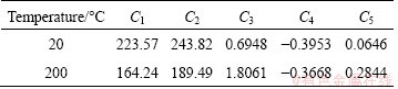
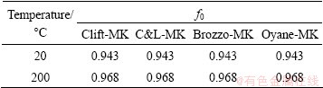
Table 4 Values of f0 in DFC-MK models
The limit strains of 5A06-O sheet at 20 and 200 ��C are determined by the DFC-MK model. By contrast, the conventional MK model is also used to compute the limiting strains. The experimental and theoretical values are described in Fig. 4.
As shown in Table 4, the value of f0 is constant in various DFC-MK models. This result is in accordance with the conclusion that f0 is the function of initial thickness of sheet metal, initial grain size and surface roughness [24]. The value of f0 at 20 ��C is less than that at 200 ��C. This reveals that the imperfection of sheet metal becomes less obvious as the temperature rises from 20 to 200 ��C.
Figures 4(a) and (b) compare the experimental and theoretical results for 5A06-O sheet at 20 ��C. The forming limit curves (FLCs) predicted by using Clift-MK, C&L-MK and Brozzo-MK models separately are in good correlation with the experimental values. The predictions by Oyane-MK model are slightly lower on right-hand of FLC than that in experiment. The FLCs calculated according to the conventional MK model do not display a good coincidence with the experimental values. When f0 is equal to 0.99, the predicted FLC is higher than the measured values in uniaxial and biaxial tensile stress state. When f0 is equal to 0.96, the predicted FLC is lower than the experimental values in plane strain state. When f0 is in the range from 0.96 to 0.99, the predictions do not agree with the experimental values in any stress state.
As can be seen in Figs. 4(c) and (d), the experimental and theoretical results for 5A06-O sheet at 200 ��C are compared. By using all the DFC-MK models, these predicted curves almost coincide and a satisfactory agreement with the experimental values is observed in the whole range of the FLCs. When f0 is equal to 0.985, the predicted FLC by the conventional MK model is nearly equal to the experimental values in plane strain state, however, higher than those in experiment in uniaxial and biaxial tensile stress states. When the value of f0 is 0.975, the predicted FLC is lower than the experimental values in plane strain state. In other cases, the predictions do not match the experimental values in any stress state.
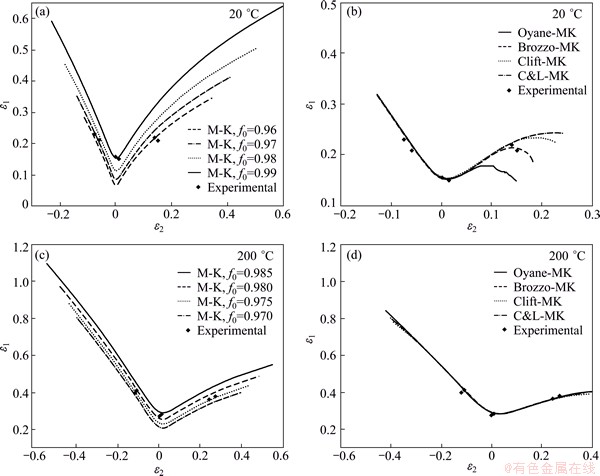
Fig. 4 Comparison of various models and experimental values (M-K represents conventional MK model)
As shown in Fig. 4, the FLCs become higher as temperature rises. The predictions by the conventional MK model are more accurate at 200 ��C than those at 20 ��C. In this situation, the theoretical predictions by the DFC-MK model are still closer to the experimental values than those by the conventional MK model.
4.2 Analysis of difference
In the conventional MK model, the failure criterion is that the ratio of the principal strain increment ����1,b in zone b to the principal strain increment ����1,a in zone a is constant, namely, ����1,b/����1,a=10. This criterion shows that the ratio has nothing to do with the loading path. Whereas, the ratios ����1,b/����1,a obtained through calculating in the DFC-MK model are presented in Fig. 5. The whole view is that the ratio ����1,b/����1,a firstly increases and then decreases when �� varies from 0 to 1, and reaches the maximum in the vicinity of the plane strain state. This change can also be reflected in the forming limit diagram. As shown in Fig. 4(a), at f0=0.96, the predicted FLD by the conventional MK model is close to the experimental data in the uniaxial and biaxial tension; however, it is significantly lower than the experimental measurements in the plane strain state. Increasing the ratio ����1,b/����1,a can raise the forming limit point in the plane strain state. At f0=0.975 shown in Fig. 4(c), the predicting trend is in accordance with the conclusion drawn from the above. The range of the ratio ����1,b/����1,a at 200 ��C is less than that at 20 ��C. This also explains that the prediction accuracy of the conventionalMK model is improved as temperature increases. In conclusion, the DFC-MK model reflects the relation between the ratio ����1,b/����1,a and the loading path by using ductile fracture criterion as the failure criterion and is more accurate than the conventional MK model.
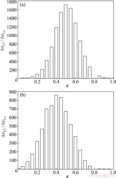
Fig. 5 values of ����1,b/����1,a with �� varying from 0 to 1 at 20 ��C (a) and 200 ��C (b)
5 Influence of through-thickness normal stress on FLD
In the DFC-MK model above, it is assumed that the model is in the plane stress condition. For some typical processes such as sheet hydroforming that is depicted in Fig. 6, the blank suffers from the through-thickness normal stress caused by the fluid pressure p. To evaluate the influence of normal stress on the yield loci variation, the first principle stress ��1 is deduced from the Hill��48 yield criterion:


 (15)
(15)
where ��s is the yield stress. According to Eq. (15), the yield loci of 5A06-O sheet at 20 ��C is obtained and shown in Fig. 7. It is obvious that the through-thickness normal stress influences the location of the yield loci evidently, which must be taken into account. The loci shift from the first quadrant to the third quadrant when the absolute value of ��3 increases.
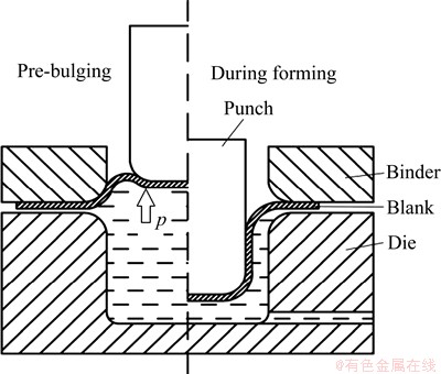
Fig. 6 Schematic diagram of sheet hydroforming
Considering the above factors, the hypothesis of the DFC-MK model should be modified to non-planar stress state. The schematic diagram is presented in Fig. 8. The through-thickness normal stress ��3 is independent of the effect of in-plane stress. To establish the relation of ��3 between zones a and b, ALLWOOD and SHOULDER [24] assumed that they are equal, namely, ��3,a=��3,b.
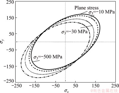
Fig. 7 Yield loci under different ��3 values at 20 ��C
The theoretical forming limit curves have been performed based on the modified DFC-MK model. Figure 9 shows the influence of ��3 that varies from 0 to -40 MPa. The forming limit improves obviously as ��3 increases. As temperature increases from 20 to 200 ��C, the same increment of ��3 has greater effect on the
improvement of the forming limit. The amount of formability improvement can be reflected by the form  that is shown as
 (16)
(16)
where  is the principle strain ��1 under the condition of plane strain in planar stress state,
  is the principle strain ��1 in non-planar stress state. The increment of ��3 from 0 to -40 MPa makes with 14.4% at 20 ��C and 23.7% at 200 ��C.
6 Application of DFC-MK model to warm hydroforming
When calculating the FLD, the loading path is linear. In actual forming process, sheet metal undergoes a complicated nonlinear loading. It has a great error to directly utilize FLD to predict sheet metal failure. In this work, The DFC-MK model is written into the subroutine VUMAT embedded in Abaqus/Explicit. As shown in Fig. 8, each cell node of the blank is equivalent to a DFC-MK model and the obtained stress/strain values are passed into VUMAT. When the integral value  ��1, it indicates that the formed part fails.

Fig. 8 Schematic diagram for DFC-MK model embedded in Abaqus/Explicit

Fig. 9 Influence of through-thickness normal stress (��3) on FLD at 20 ��C (a) and 200 ��C (b)
Warm hydroforming has many virtues and has gained increasing interest in industries recently [25,26]. In this work, The DFC-MK model has been implemented in Abaqus/Explicit to simulate cylindrical cup hydroforming process. The diameter of the blank is 220 mm at 20 ��C and 260 mm at 200 ��C. The frictional coefficient between the blank and the punch is assumed to be 0.15. The frictional coefficient between the blank and the die/binder is set to be 0.05.
In the simulation, the C&L-MK model, which is the most accurate model, is implemented to verify the precision. By using the stresses/strains history obtained by the FE simulation and the obtained C2 and f0, integral I is computed for each element and some important forming steps. The condition of forming limit is satisfied when integral I is equal to 1.
The prediction result of the C&L-MK model at 20 ��C is depicted in Fig. 10. Figure 10(a) shows the distribution of the integral I at different heights. Along with the increase of the punch stroke, integral I of punch nose corner increases. When the punch stroke reaches 32.3 mm, integral I exceeds 1. Figure 10(b) presents the thickness distribution when the punch stroke is 32.3 mm in simulation and shows that the failure point is in the most severe thinning area. As shown in Fig. 10(c), the measured height is 35.2 mm and the error is 8.23%.
The prediction result of the C&L-MK model at 200 ��C is depicted in Fig. 11. With the increase of the punch stroke, integral I of punch nose corner increases. When the punch stroke reaches 42.2 mm, integral I exceeds 1, which indicates that the cylindrical cup has cracked. Figure 11(b) presents the thickness distribution when the punch stroke is 42.2 mm in the simulation and shows that the failure point is in the most severe thinning area. As shown in Fig. 11(c), the measured height is 46.5 mm and the error is 9.24%.
The difference between finite element analysis and experimental results comes from two aspects. Firstly, the process parameters such as material model, the friction coefficient and liquid pressure, cannot fully reflect the real situation. In addition, the value predicted by the DFC-MK model shows that sheet metal is in necking zone. From Figs. 10(c) and 11(c), the formed parts have generated evident fracture defect. The predicted punch stroke should be less than that in the experiment and the contrasts also confirm the trend. The DFC-MK model turns out to be correct in predicting forming limit of 5A06-O sheet hydroforming.

Fig. 10 Distribution of integral I (a), thickness distribution at punch stroke of 32.3 mm (b) and formed cups (c) at 20 ��C

Fig. 11 Distribution of integral I (a), thickness distribution at punch stroke of 42.2 mm (b) and formed cups (c) at 200 ��C
7 Conclusions
1) For 5A06-O aluminum alloy sheet, uniaxial tensile, wide sheet bending and hydrobulging are performed at 20 and 200 ��C. The experimental values of FLDs and fracture strains are measured through these tests. The measured material properties of 5A06-O sheet which are used in Swift��s power law and Hill��48 yield criterion are also determined.
2) In order to determine material constants C of ductile fracture criteria and the initial thickness imperfection parameter f0, a new computing method based on the modified MK model is proposed.
3) The DFC-MK model is proposed to predict the forming limit diagram of sheet metal. The results of the FLDs based on the DFC-MK model are found to correlate quite well with the experimental observations and be more accurate than the conventional MK model.
4) The cylindrical cup hydroforming tests at 20 and 200 ��C are carried out to verify the DFC-MK model. The C&L-MK model, which includes the influence of through-thickness normal stress, is implemented in ABAQUS to determine the punch stroke when the formed cup is failure. The predicted results show that the error is 8.23% at 20 ��C and 9.24% at 200 ��C.
References
[1] SWIFT H W. Plastic instability under plane stress [J]. Journal of the Mechanics and Physics of Solid, 1952, 1(1): 1-18.
[2] HILL R. On discontinuous plastic states with special reference to localized necking in thin sheets [J]. Journal of Mechanics and Physics of Solids, 1952, 1(1): 19-31.
[3] KEELER S P, BACKOFEN W A. Plastic instability and fracture in sheets stretched over rigid punches [J]. ASM Transactions Quarterly, 1963, 56(1): 25-48.
[4] MARCINIAK Z, KUCZYNSKI K. Limit strains in the processes of stretch-forming sheet metal [J]. International Journal of Mechanical Science, 1967, 9(3): 609-620.
[5] NAKA T, NAKAYAMA Y, UEMORI T, HIRO R, YOSHIDA F. Effects of temperature on yield locus for 5083 aluminum alloy sheet [J]. Journal of Materials Processing Technology, 2003, 140(S1-S3): s494-s499.
[6] LOU Yan-shan, HUH H. Prediction of ductile fracture for advanced high strength steel with a new criterion: Experiments and simulation [J]. Journal of Materials Processing Technology, 2013, 213(8): 1284-1302.
[7] YAGAMI T, MANABE K, MIYAMOTO T. Ductile fracture behavior of 5052 aluminum alloy sheet under cyclic plastic deformation at room temperature [J]. Journal of Materials Processing Technology, 2009, 209(2): 1042-1047.
[8] LEI Li-ping, KIM J. Bursting failure prediction in tube hydroforming process by using rigid-plastic FEM combined with ductile fracture criterion [J]. International Journal of Mechanical Sciences, 2002, 44(7): 1411-1428.
[9] TAKUDA H, OZAWA K, HAMA T, YOSHIDA T, NITTA J. Forming limit prediction in bore expansion by combination of finite element simulation and ductile fracture criterion [J]. The Japan Society for Technology of Plasticity, 2009, 50(8): 1930-1934.
[10] ZHAN Mei, GU Chuang-guo, JIANG Zhi-qiang, HU Li-jin, YANG He. Application of ductile fracture criteria in spin-forming and tube-bending processes [J]. Computational Materials Science, 2009, 47(2): 353-365.
[11] TAKUDA H, MORI K. Finite element analysis of limit strains in biaxial stretching of sheet metals allowing for ductile fracture [J]. International Journal of Machine Tools and Manufacturing, 2000, 42(4): 785-798.
[12] VALLELLANO C, MORALES D, GARCIALOMAS F J. A study to predict failure in biaxially stretched sheets of aluminum alloy 2024-T3 [J]. Materials and Manufacturing Processes, 2008, 23(3): 303-310.
[13] JAIN M, ALLIN J, LLOYD D J. Fracture limit prediction using ductile fracture criteria for forming of an automotive aluminum sheet [J]. International Journal of Mechanical Science, 1999, 41(10): 273-288.
[14] YU Xin-hong, ZHAI Ni-zhi, ZHAI Jiang-bo. Prediction of the forming limit of sheet metals based on Oyane ductile fracture criterion [J]. Materials Science and Technology, 2009, 17(5): 738-740. (in Chinese)
[15] YU Zhong-qi, YANG Yu-ying, WANG Yong-zhi, SUN Zhen-zhong. Application of ductile fracture criterion to prediction of forming limit in aluminum alloy sheet forming [J]. The Chinese Journal of Nonferrous Metals, 2003, 13(5): 1223-1226. (in Chinese)
[16] BANABIC D, SOARE S. On the effect of the normal pressure upon the forming limit strains [C]//Proceedings of Numisheet 2008 Conference. Interlaken, Switzland, 2008: 199-204.
[17] NURCHESHMEH M, DANIEL E G. Influence of out-of-plane compression stress on limit strains in sheet metals [J]. International Journal of Material Forming, 2011, 5(3): 213-226.
[18] NURCHESHMEH M, GREEN D E. Effect of sheet mechanical properties on forming limits in presence of a through-thickness stress [C]//Proceedings of AIP Conference. Belfast, United Kingdom, 2011: 171-176.
[19] TAKUDA H, MORI K, HATTA N. The application of some criteria for ductile fracture to the prediction of the forming limit of sheet metals [J]. Journal of Materials Processing Technology, 1999, 95(1-3): 116-121.
[20] COCKCROFT M G, LATHAM D J. Ductility and the workability of metals [J]. Journal of the Institute of Metals, 1968, 96(2): 333-339.
[21] OYANE M, SATO T, OKIMOTO K. Criteria for ductile fracture and their applications [J]. Journal of Mechanical Working Technology, 1980, 4(1): 65-81.
[22] DASAPPA P, INAL K, MISHRA R. The effects of anisotropic yield functions and their material parameters on prediction of forming limit diagrams [J]. International Journal of Solids and Structures, 2012, 49(25): 3528-3550.
[23] NURCHESHMEH M, GREEN D E. Investigation on the strain-path dependency of stress-based forming limit curves [J]. International Journal of Material Forming, 2011, 4(1): 25-37.
[24] ALLWOOD J M, SHOULDER D R. Generalised forming limit diagrams showing increased forming limits with non-planar stress states [J]. International Journal of Plasticity, 2009, 25(7): 1207-1230.
[25] LANG Li-hui, WANG Yong-ming, XIE Ya-su, YANG Xi-ying, XU Ying-qiang. Pre-bulging effect during sheet hydroforming process of aluminum alloy box with unequal height and flat bottom [J]. Transactions of Nonferrous Metals Society of China, 2012, 22(S2): s302-s308.
[26] LIU Gang, ZHANG Wen-da, HE Zhu-bin, YUAN Shi-jian, LIN Zhe. Warm hydroforming of magnesium alloy tube with large expansion ratio within non-uniform temperature field [J]. Transactions of Nonferrous Metals Society of China, 2012, 22(S2): s408-s415.
�������Զ����������MKģ�ͼ����ڳ�Һ�ȳ����е�Ӧ��
��ϣӢ�������ԣ����������� ��
�������պ����ѧ ��е���̼��Զ���ѧԺ������ 100191
ժ Ҫ����MKģ�������Զ��������ϣ����Ԥ�ⲻͬ�¶���5A06-O���Ͻ��ij��μ�����ģ�͡����ڿ����������飬Ӧ���µ�����MKģ��ȷ�����ϳ���(C)�ͳ�ʼ��Ȳ�����( f0)��ͨ���������ģ�ͼ���õ�20��200 ��C�µij��μ���ͼ������ĺ�ȷ���Ӧ���Գ��μ���Ӱ�������ģ�ͣ���Ƕ��Abaqus/Explicit�У�����Ͳ�μ���Һ���β�������֤������������봫ͳMKģ�ͶԱȿ�֪����ģ��Ԥ��ij��μ���ͼ��ʵ��ֵ���ӽӽ�����20��200 ��C�£���Һ�ȳ���ģ����ʵ��֮������ֱ�Ϊ8.23%��9.24%����֤��ģ�͵���Ч�ԡ�
�ؼ��ʣ�MKģ�ͣ����Զ�����Һ�ȳ��Σ���ȷ���Ӧ��
(Edited by Wei-ping CHEN)
Foundation item: Project (51175024) supported by the National Natural Science Foundation of China
Corresponding author: Li-hui LANG; Tel/Fax: +86-10-82316821; E-mail: lang@buaa.edu.cn
DOI: 10.1016/S1003-6326(15)63974-7
Abstract: A modified MK model combined with ductile fracture criterion (DFC-MK model) is proposed to compute the forming limit diagrams (FLDs) of 5A06-O aluminum alloy sheet at different temperatures. The material constant (C) of ductile fracture criterion and initial thickness imperfection parameter (f0) at various temperatures are determined by using a new computing method based on wide sheet bending test. The FLDs at 20 and 200 ��C are calculated through the DFC-MK model. The DFC-MK model, which includes the influence of through-thickness normal stress, is written into the subroutine VUMAT embedded in Abaqus/ Explicit. The cylindrical cup hydroforming tests are carried out to verify the model. The results show that compared with experimental observations, the predicted FLDs based on DFC-MK model are more accurate than the conventional MK model; the errors between the simulations and experiments in warm hydroforming are 8.23% at 20 ��C and 9.24% at 200 ��C, which verify the effectiveness of the proposed model.
