
Trans. Nonferrous Met. Soc. China 27(2017) 2317-2333
Hybrid multi-objective optimization of microstructural and mechanical properties of B4C/A356 composites fabricated by FSP using TOPSIS and modified NSGA-II
Mostafa AKBARI1, Mohammad Hasan SHOJAEEFARD2, Parviz ASADI3, Abolfazl KHALKHALI1
1. School of Automotive Engineering, Iran University of Science and Technology, Tehran, Iran;
2. School of Mechanical Engineering, Iran University of Science and Technology, Tehran, Iran;
3. Faculty of Engineering, Imam Khomeini International University, Qazvin, Iran
Received 6 August 2016; accepted 23 March 2017
Abstract:
A356 alloy was used as the base metal to produce boron carbide (B4C)/A356 composites using friction stir processing (FSP). The microstructural and mechanical properties of B4C/A356 composites were optimized using artificial neural network (ANN) and non-dominated sorting genetic algorithm-II (NSGA-II). Firstly, microstructural properties of the composites fabricated in different processing conditions were investigated. Results show that FSP parameters such as rotational speed, traverse speed and tool pin profile significantly affect the size of the primary silicon (Si) particles of the base metal, as well as the dispersion quality and volume fraction of reinforcing B4C particles in the composite layer. Higher rotational to traverse speeds ratio accompanied by threaded pin profile leads to better particles distribution, finer Si particles and smaller B4C agglomerations. Secondly, hardness and tensile tests were performed to study mechanical properties of the composites. FSP changes the fracture mechanism from brittle form in the as-received metal to very ductile form in the FSPed specimens. Then, a relation between the FSP parameters and microstructural and mechanical properties of the composites was established using ANN. A modified NSGA-II by incorporating diversity preserving mechanism called the �� elimination algorithm was employed to obtain the Pareto-optimal set of FSP parameters.
Key words:
friction stir processing; B4C; composite; multi-objective optimization; TOPSIS method;
1 Introduction
Aluminum alloy based composites are known as a group of advanced materials for their lightweight with enhanced mechanical properties, and good wear resistance properties. Mechanical properties of Al alloys can be significantly improved by introducing a hard phase either in particles or fiber form and forming composites. Among different parameters affecting the mechanical properties of composites, the reinforcing particles type plays an important role. Boron carbide that ranks the third in hardness only after cubic boron nitride and diamond [1,2] is an interesting ceramic particle for various applications including neutron absorption, impact resistance and wear resistance. It has low specific gravity, excellent chemical resistance, and high hardness and stiffness which are crucial requirements for effective reinforcing particles. B4C/aluminum composites have the potential to combine the high stiffness and hardness of B4C reinforcing particles with the ductility of aluminum, and without defeating the goal of obtaining a strong and low-density material [2-4].
Al-Si alloys like A356 include 85%-90% of the total casting aluminum parts and are widely used in automobile and aerospace industries because of their high wear resistance, low thermal expansion, good castability and excellent casting characteristics [5-11]. Many factors could influence the production quality of Al-Si casting parts, and generally the microstructure and other alloy ingredients are crucial factors to achieve optimum mechanical properties. However, some mechanical properties of Al-Si alloys, in particular, toughness, ductility, and fatigue resistance, are limited by microstructural drawbacks of these alloys: porosity, needle-like Si particles with high aspect ratios, and ��(Al) dendrites [11-13].
In the past two decades, several modification and heat treatment techniques like modifier treatment, heat treatment and stirring of solidification have been employed to improve microstructural properties of these alloys [14]. Neither the modification nor the heat- treatment methods mentioned above can redistribute the Si particles uniformly into the aluminum matrix and eliminate the porosity effectively in A356. As a result, a more effective modification technique is needed to improve microstructural properties of these alloys.
Friction stir processing (FSP), a solid-state process developed based on friction stir welding (FSW), as another surface modification method, can be employed to improve the mechanical properties of alloys [15-20]. Additionally, it has become very popular in preparation of the surface layer composites.
In FSP, a non-consumable rotational tool, consisting mainly of a pin and a shoulder, is plunged into the metal plates and traversed in desired direction. It produces a highly plastically deformed zone through the associated stirring action. The severe plastic deformation, material mixing and thermal exposure over the FSP result in the refinement of microstructure, densification and homogenization [21-23]. FSP parameters like tool rotational and traverse speeds and tool design have significant effects on the microstructural properties obtained from FSP. As a result, these parameters affect the mechanical characteristics of the FSPed specimens. The optimal FSP parameters cannot be easily achieved due to non-linear and high complex characteristic of the process. Mathematical models of FSP are not capable to describe the nonlinear characteristics of the process efficiently. To solve this problem, intelligent systems like artificial neural networks (ANN) can be employed. An ANN which is inspired by natural neural network can be used as a powerful tool to obtain the correlations between the FSW parameters and process properties. ASADI et al [21] employed ANN to obtain a relation between the FSP parameters, hardness and grain size. SHOJAEEFARD et al [24] developed ANN to achieve the relation between FSW parameters and mechanical properties of the weld. They showed that ANN model can accurately predict the mechanical properties as functions of FSW parameters.
The quality of the fabricated composites depends on many competing criteria such as hardness, ultimate tensile strength (UTS), Si particles size and distribution, and dispersion of reinforcing particles. As results to consider all such criteria simultaneously, a complex multi-objective optimization (MOP) problem must be solved. To solve this problem, many successful methods are proposed by numerous researchers. One of the best methods to overcome multi-objective problem is non-dominated sorting genetic algorithm-II (NSGA-II) developed by SHOJAEEFARD et al [24]. This Pareto- based approach generates a set of non-dominated solutions which are called Pareto front.
In this study, boron carbide (B4C)/A356 composites were fabricated on Al-Si alloy using FSP. The effects of process parameters on the size of Si particles (of the base metal), hardness, axial force and UTS were carefully investigated. Then, an integrated approach using ANN and hybrid multi-objective optimization was developed to optimize objective functions such as Si particles size, hardness, axial force and UTS simultaneously.
2 Experimental
2.1 Materials
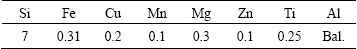
A356 cast alloys with the thickness of 10 mm and B4C particles with the size of 10 ��m were used as reinforcing particle to fabricate composite surface layers. The chemical composition of A356 is given in Table 1 where the Al as a base alloy contains 7% of silicon.
Table 1 Chemical composition of as-cast A356 aluminum plates (mass fraction, %)
2.2 Friction stir processing
In order to select the best FSP tool pin profile, different tool pin profiles of cylindrical, square and threaded were employed in this study (Fig. 1), and all of them were made of H13 steel. The tools dimensions are shown in Fig. 1 and pin lengths for all of the tools were 3.5 mm. Moreover, to optimize process parameters like traverse and rotational speeds, the composites were fabricated with different tool rotational speeds of 800, 1200 and 1600 r/min, and tool traverse speeds of 8, 32 and 80 mm/min.
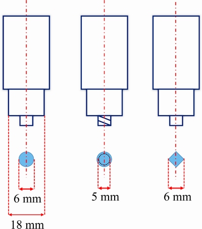
Fig. 1 Dimensions of FSP tools used in this study
For composite fabrication, firstly reinforcing particles were placed into a square groove machined with dimensions of 3.5 mm in depth and 1.4 mm in width. Then, the grove��s surface was initially closed with a pin-less tool to prevent sputtering the reinforcement particles during FSP. Finally, the A356 was processed by FSP along the groove using different process conditions.
2.3 Microstructure and hardness
Optical microscope (OM) was used to investigate microstructural properties of the fabricated composites. In order to reveal the microstructures of the specimens, the composites were polished and then etched using Keller��s reagent. The size of Si particles was determined using an image analyzing software.
To calculate the hardness of composites, Vickers microhardness was measured at different locations of the composites. Microhardness tests were performed according to the Vickers method (ASTM E384) and to report an average value for hardness of stir zone (SZ), and 10 indentation points were selected in deferent rejoins of the SZ.
2.4 Tensile measurements
The tensile properties of the composites were measured at a constant crosshead speed of 2 mm/min. The tensile specimens were cut in the longitudinal direction along the FSP line.
2.5 Force acquisition
In order to determine the axial force during FSP, a specially designed dynamometer was employed (Fig. 2). In this dynamometer, two bending load cells were used for axial force measurement. There were two bending load cells at the center line of backing plate. Due to statistical condition when an amount of force, for instance tool force, acted on this backing plate, two reversed forces acted from load cell to backing plate to meet the statistical conditions. This system is able to measure axial force up to 70 kN with an accuracy of 12 N at a recording rate of 10 records per second. Moreover, four holders are used to increase dynamometer resistance against vibration over the process.
To record the dynamometers�� data, one requires a two-channeled 24-bit data logger with a microprocessor, which has the ability to convert analog signals into digital ones. This microprocessor could be connected to the computer through a USB cable and the results can be saved as an excel spread sheet using a Matlab program [8].
2.6 Composites preparation
Figure 3 illustrates the microstructures of the composites fabricated by different pin profiles at tool rotational speed and traverse speed of 1200 r/min and 32 mm/min, respectively. As shown in Fig. 3(a), in the composite fabricated via a circular pin profile, different bands involving different percentages of reinforcing particles were formed in the SZ. On the other side, the distribution of particles was improved in the composite fabricated via the square pin profile compared to the composite fabricated via the circular pin; however, it was not still homogenous (Fig. 3(b)). As shown in Fig. 3(c), only threaded pin profile can uniformly disperse the reinforcing particles in A356 matrix. This may be related to vertical motion produced by threaded pin profile. There is not such motion when square or circular pin profile is used. As a result, for composites fabrication, threaded pin profile was used.
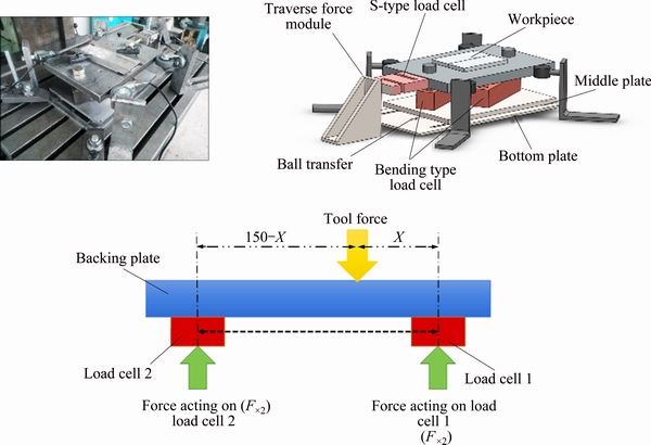
Fig. 2 Schematic of dynamometer used in this study
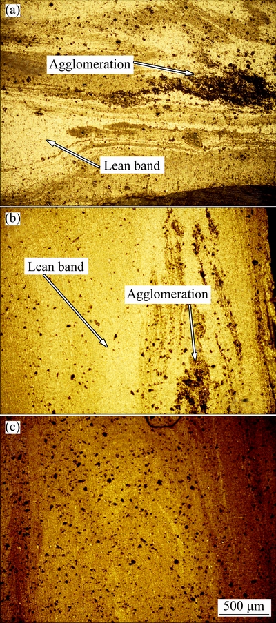
Fig. 3 Microstructures of composites fabricated with different pin profiles of circular (a), square (b) and threaded (c)
Figure 4 shows macro-images of two composites produced at tool rotational and traverse speeds of 1200 r/min and 32 mm/min, respectively, with and without change in direction of tool rotation between passes. It is demonstrated that the dispersion of reinforcing particles in metal matrix is more uniform when tool rotational direction is changed between passes. Generally in FSP, the materials migrate toward advancing side (AS) due to material flow characteristic of process [25,26]. When tool rotational direction does not change, the particles migrate to AS in each pass and after four passes the powder agglomeration occurs on the AS. However, by changing the tool rotational direction the AS and retreating side (RS) locations change together between passes, leading to change in the flow pattern of the material and the particles distribution. Therefore, all experiments were done with change in direction of FSP tool rotation between passes.
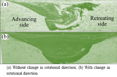
Fig. 4 Macro-images of composites fabricated by 4-pass FSP
3 Results and discussion
In this section, under several subsections, the effects of rotational speed and traverse speed on the microstructural and mechanical properties of unreinforced and B4C-reinforced FSPed specimens are considered. Then, a multi-objective optimization model is presented to optimize the FSP parameters using a modified NSGA-II and TOPSIS.
3.1 Microstructural properties
Figure 5 shows the microstructures and Si particles size of the unreinforced FSPed specimens in SZ at various tool rotational and traverse speeds. As shown in Fig. 5(a), coarse needle-like Si particles are observed at the A356 base material, but they are not distributed uniformly. Such a microstructure leads to the brittle behavior of this alloy. On the other hand, for FSPed specimens at all tool traverse and rotational speeds, the coarse needle-like Si particles are broken up to very fine circular particles and almost homogenously dispersed in the SZ, and no porosity can be observed in the SZ. Normally in the cast alloys, there are some amounts of porosity especially in the Al-Si alloys and the increase in the amount of Si causes more porosity in the structure. FSP, as a microstructural modifying process, can easily eliminate this drawback by severe plastic deformation and forging the materials under process inside the processing zone by tool shoulder and tilt angle [27,28].
It can be understood from Fig. 5 that the increase in rotational speed or decrease in traverse speed leads to the decrease in the Si particles size in SZ. For example, by increasing rotational speed from 800 to 1600 r/min at constant traverse speed of 32 mm/min, Si particles size decreases from 4.2 to 2.6 ��m (Figs. 5(e) and (f)). On the other hand, by increasing tool traverse speed from 8 to 80 mm/min at constant tool rotational speed of 1200 r/min, Si particles size increases from 1.8 to 6.7 ��m (Figs. 5(b) and (d)). This may be attributed to the fact that an increase in tool rotational speed or a decrease in tool traverse speed leads to an increase in the amount of effective strain in the processing zone, resulting in a severer disruption of Si particles. This result is in line with that of MA et al [29], showing that an increase in tool rotational speed or a decrease in tool traverse speed leads to a decrease in Si particles size. However, in some other studies, contrary results have been reported regarding the effect of tool traverse and rotational speeds on the Si particles size in Al-Si alloys. For example, MAHMOUD and MOHAMED [30] reported that the average Si particles size is increased by an increase in the rotational speed or a decrease in tool traverse speed. This result can be justified by the reason that, as the rotational speed/traverse speed ratio (w/v) increases, the materials become softer and it will be easier for the Si particles to flow with the material without breakage. However, in the present study the Si particles size is reduced as the w/v increases.
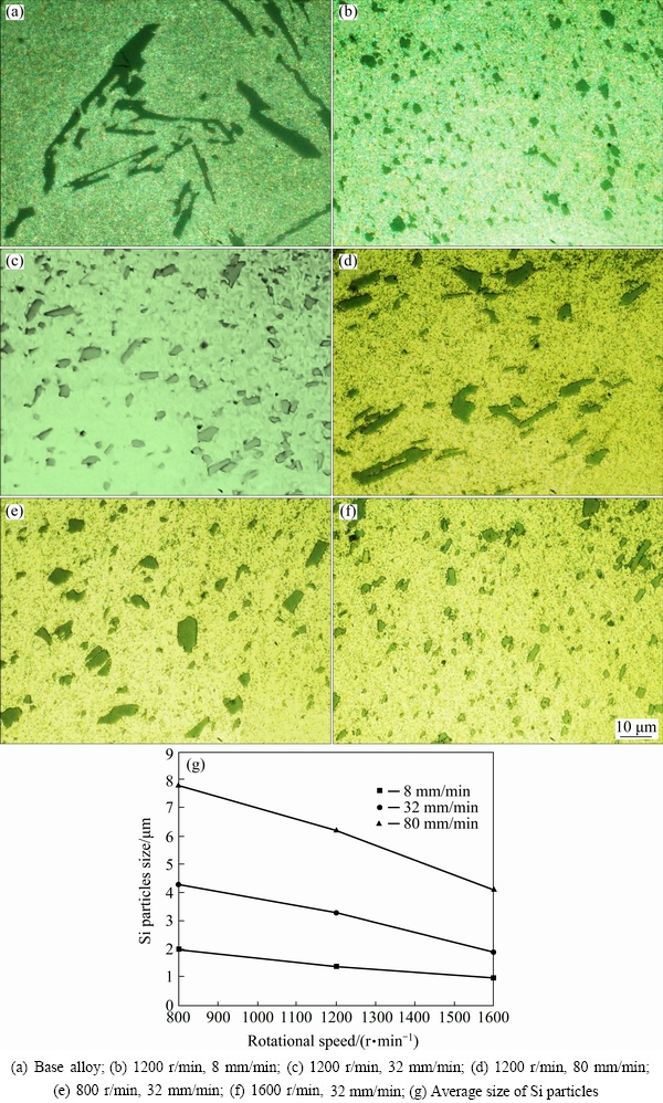
Fig. 5 Microstructures of base alloy and FSPed specimens in SZ at various tool rotational and traverse speeds
Figure 6 shows the macro-images of SZ in the FSPed specimen produced with B4C reinforcing particles at different tool rotational and traverse speeds. As shown in Fig. 6, by increasing the w/v, both the SZ area and the particles distribution quality are increased. On the other hand, increasing the area of SZ leads to a decrease in actual volume fractions of the reinforcing particles in the composite layer. The theoretical and actual volume fractions of reinforcing particles can be determined using the following equations [31]:
 (1)
(1)
where ��t is the theoretical volume fraction; Sg is the area of groove; Stp is the projected area of tool pin.
 (2)
(2)
where ��a is the actual volume fraction; Ssc is the area of surface composite.
 (3)
(3)
where Lg, Dg, Dp and Lp are groove width, groove depth, pin diameter and pin length, respectively.
The theoretical volume fraction of composite layers is 12%. However, the actual particle volume fraction is lower than that calculated by theory due to the expansion of the SZ as a result of presence of high temperatures and strains around the tool pin. The actual volume fraction is 9.5%-10%.
Figure 7, showing the SEM images from the SZ, illustrates the particles distribution in the composites fabricated at different rotational and traverse speeds. The particles distribution in the composites fabricated at a traverse speed of 8 mm/min is uniform (Fig. 7(a)), and by increasing tool rotational speed from 800 to 1600 r/min, the volume fraction of the reinforcing particles is decreased due to an increase in the SZ area (Fig. 7(b)). Additionally, in the composites fabricated at a traverse speed of 32 mm/min, by increasing rotational speed both the particles fraction and their clusters size in the SZ are decreased (Figs. 7(c) and (d)). In the composites fabricated at a traverse speed of 80 mm/min and a rotational speed of 800 r/min (Fig. 7(e)), particles agglomeration is observed due to insufficient material flow at low w/v ratio, but by increasing rotational speed to 1600 r/min the particles distribution is improved. It is well accepted that increasing tool rotational speed or decreasing tool traverse speed results in an increase in the temperature and the material flow.
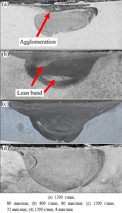
Fig. 6 Macro-images of SZ in FSPed specimens produced at different tool rotational and traverse speeds
Moreover, the density of the metal matrix composites containing B4C particles is decreased compared with that of base metal. This is related to the lower density of B4C particles (2.504 g/cm3) compared to Al-Si (Density of Al-A356.1 is 2.685 g/cm3) [27,32]. By increasing tool rotational speed or decrease in tool traverse speed, the density of composites increases due to the decrease of fracture of reinforcing particles in the metal matrix. The relationship between morphology and volume fraction of reinforcing particles and their distance to each other can be expressed by Eq. (4):
 (4)
(4)
where �� represents the distance between reinforcing particles, r is particles radius, and �� is the volume fraction of particles. Supposing a constant radius for particles, the increase in volume fraction of reinforcements will cause a decrease in the distance between particles. As a result, a decrease in tool rotational speed or an increase in tool traverse speed (the decrease in w/v ratio) leads to a decrease in the distance between reinforcing particles due to the increase in actual volume fraction of particles as discussed before. Decreasing the distance between particles may lead to an increase in the stress for shearing of dislocations and consequently a decrease in yield stress as reported by SHIRVANIMOGHADDAM et al [27,32].
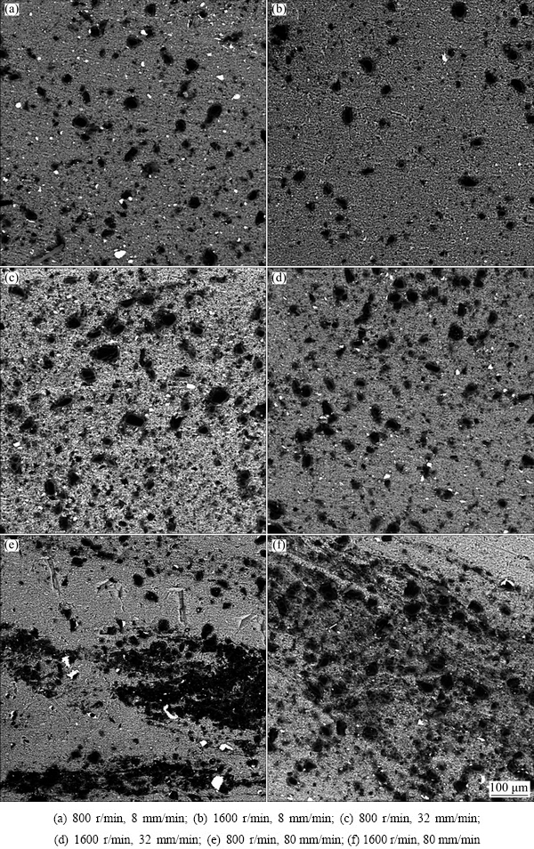
Fig. 7 SEM images of SZ showing particles distribution in composites produced at different tool rotational and traverse speeds
3.2 Axial force during FSP
The forces applied to the FSP tool are important for several reasons. Firstly, when the tool undergoes a higher load, its wear rate increases severely, leading to a growth in processing cost by tool lifetime reduction [25]. Secondly, joint contaminants resulted from tool wear may lead to deterioration of the FSPed specimen.
The average axial force during FSP at different tool rotational and traverse speeds is shown in Fig. 8. It illustrates that, an increase in the w/v results in a reduction in the tool axial force. This result can be attributed to the increase in the amount of generated heat that leads to more material softening and less material resistance against the tool advance [8,9].
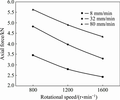
Fig. 8 Variation of average axial force versus tool rotational and traverse speeds
3.3 Microhardness
Figure 9(a) illustrates the microhardness profile of the FSPed specimens fabricated at tool rotational and traverse speeds of 1200 r/min and 32 mm/min, respectively. It is obvious that the hardness in SZ is significantly higher than that in base metal (BM). This improvement may be due to microstructural enhancement such as Si particles breakage, coarse ��(Al) dendrites elimination, and grain refinement as discussed before. Moreover, the hardness on AS is higher than that of on RS. It may be due to the fact that the amount of material shearing on AS is higher than that on the RS, leading to smaller Si particles [25]. Additionally, the hardness in TMAZ is higher than that of BM, but lower than that in SZ. Materials in TMAZ which experienced lower strain than those in the SZ resulted in larger Si particles [33].
Figure 10 shows the hardness variation for the composites fabricated at different tool rotational and traverse speeds. The hardness of A356 base alloy is about HV 46. Composites reinforced with B4C show a significant improvement compared with the base alloy.
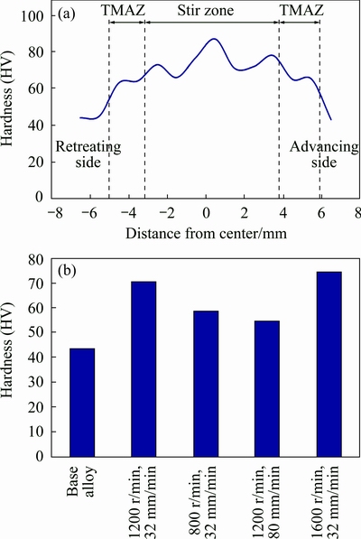
Fig. 9 Variation of hardness of different SZ subdomains (a) and composites (b) at various tool rotational and traverse speeds
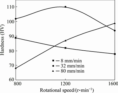
Fig. 10 Hardness of unreinforced FSPed specimens at different process parameters
This improvement may be contributed to microstructural enhancement such as Si particles breakage, coarse ��(Al) dendrites elimination, and grain refinement due to severe plastic deformation and recovery, as well as presence of hard reinforcing particles in the matrix. To investigate the effects of microstructural refinement on hardness improvement regardless of reinforcement presence, the hardness values of unreinforced FSPed samples fabricated at different tool rotational and traverse speeds were investigated (Fig. 9(b)). It is illustrated in Fig. 9(b) that, an increase in w/v results in an increase in the average hardness of the FSPed specimens. This result is in agreement with result that a reduction in tool rotational speed or a rise in tool traverse speed resulted in decreasing the hardness value of the FSPed specimens with reinforcement [29]. Indeed, at higher w/v ratios, the amounts of plastic deformation and strain rate are higher, which leads to more breakage of Si particles and thus, the more and the finer the Si particles are, the higher the hardness is.
However, an opposite behavior about the effect of tool traverse and rotational speeds on the hardness of Al-Si alloys has been reported. TUTUNCHILAR et al [14] reported that average hardness decreased by increasing rotational speed or reducing the tool traverse speed. To explain the reason of this observation, two important factors should be taken into account.
1) Si particles size decreases by increasing tool rotational speed or decrease in tool traverse speed, as discussed before. SHINODA and KAWAI [34] concluded that breaking down and homogenization of the Si needles lead to an increase in hardness of the SZ. Moreover, an increase in tool rotational speed or a decrease in tool traverse speed results in decreasing the grain size due to the generation of more nucleation sites as reported by ALIDOKHT et al [7]. Furthermore, by increasing tool rotational speed or decreasing the tool traverse speed, more Mg2Si precipitates dissolve into the A356 matrix [29]. This factor provides a larger precipitation strengthening effect after natural aging of the FSP samples. Finally, smaller Si particles produced by the FSP exert an additional strengthening effect on aluminum matrix through dislocation/particle interaction.
2) By an increase in rotational speed or a decrease in traverse speed, the coefficient of thermal expansion (CTE) becomes smaller due to Si particles size reduction and homogenization of microstructure. The decrease in CTE occurs mainly due to residual stress reduction based on the TUTUNCHILAR et al [14]. According to dislocation formation mechanisms, by decreasing CTE and consequently reduction in thermal stress (due to an increase in tool rotational speed or a decrease in tool traverse speed), dislocation density decreases, and consequently hardness reduces.
As mentioned before, by increasing tool rotational speed or decreasing tool traverse speed, the hardness of the FSPed specimens raises. As a result, grain refinement accompanied by uniform distribution of finer Si particles is the major factor to change the hardness value.
In order to better understand the effect of Si particles size on hardness value of the FSPed specimens, another experiment was carried out with circular pin profile at a tool rotational speed of 1200 r/min, and a tool traverse speed of 8 mm/min with and without cooling. The water cooling was conducted at a water flow rate of 450 mL/min.
Figure 11 illustrates microstructures of the FSPed specimens fabricated with and without cooling. Si particles sizes for the FSPed specimens with and without coolant are about 4.5 and 1.2 ��m, respectively. Additionally, the hardness of specimens fabricated with cooling is about HV 91, showing HV 31 higher than that of the specimen without sing coolant. This experiment confirms that the major factor for changing the hardness value is the more uniform distribution of finer Si particles, as well as grain refinement.
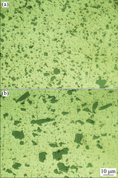
Fig. 11 Microstructures of FSPed specimens fabricated with (a) and without (b) cooling
Another important reason for hardness improvement of the composite is the presence of the reinforcing particles with higher hardness in the metal matrix. This occurrence can be attributed to several reasons: 1) the distribution of the B4C particles as a very hard component inside the A356 matrix, 2) significant CTE difference between the A356 base alloy and the B4C particles leads to high amount generation of geometrically necessary dislocations (GNDs) over the thermal cycles forced by the process inherent [35,36], and 3) Orowan strengthening mechanism. However, the latter mechanism is less effective in hardness improvement for micron-sized particle reinforcements and generally becomes more effective by reducing the particle size.
As shown in Fig. 10, the variation of hardness at different tool traverse speeds is not the same. This behavior may be due to three affecting factors which influenced the hardness value of composites in the opposite directions. On one hand, by increasing the tool rotational speed or decreasing the tool traverse speed, the actual volume fractions of the reinforcing particles are decreased (Fig. 7), leading to a decrease in the hardness of composites. On the other hand, by increase in the w/v ratio, distribution of the particles in Al matrix is improved (Fig. 7), leading to an improvement in the composites hardness. Moreover, as cited before, an increase in the w/v ratio leads to a more refinement in Si particles, which results in the hardness improvement.
For the composites produced at a tool traverse speed of 8 mm/min, by increasing the tool rotational speed the hardness value is reduced. Since the distribution of reinforcing particles is uniform for the composites fabricated at tool traverse speed of 8 mm/min (Fig. 7), the reason behind hardness change is related to two other factors including Si particles size and actual volume fractions of reinforcing particles. Firstly, an increase in tool rotational speed results in an improvement in the hardness due to the microstructural (Si particle) refinement, and secondly, this increase results in a decrease in the actual volume fraction of reinforcing particles, leading to a decrease in the composite hardness. Therefore, in this case, the actual volume fraction of reinforcing particles is the major factor for the reduction in the hardness value.
For the composites produced at a tool traverse speed of 32 mm/min, as the tool rotational speed increases from 800 to 1200 r/min, firstly hardness is improved and then by further from 1200 to 1600 r/min, it drops down. It seems that at first part (800 to 1200 r/min) both Si particles size and particles distribution are improved, but in the second part (1200 to 1600 r/min) the reduction in actual volume fraction of the reinforcing particles is dominant factor which results in a decrease in hardness value.
As particles distribution is inhomogeneous for the composites fabricated at a tool traverse speed of 80 mm/min, therefore, the hardness increase through the particles distribution improvement is expected as the tool rotational speed rises.
3.4 Effects of process parameters on UTS
Figure 12 shows the variation of UTS of the composites fabricated at different tool rotational and traverse speeds. The UTS of A356 base alloy is about 90 MPa, very much lower than that of the fabricated composites. This behavior is due to the coarse needle-like Si particles, ��(Al) dendrites, and porosities in as-cast A356 metal matrix. Crack propagation and interfacial separation were formed during tensile deformation around large needle-like Si particles and A356 matrix defects, like porosity. It should be noticed that the effect of Si particles refinement on UTS improvement is very much higher than its effect on hardness increase. Although the hardness is improved by Si particles refinement, the UTS, besides by the particle refinement, is revitalized by elimination of the large and needle-like Si components as well as probable porosities.
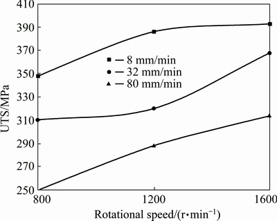
Fig. 12 Variation of UTS at various tool rotational and traverse speeds
Moreover, the addition of B4C reinforcements into the A356 matrix improves the tensile properties of the fabricated composites by extra refining the microstructure and creating more geometrically necessary dislocations as discussed before. It is evident that, the more the dislocations in the microstructure are, the harder the materials flow during tensile test is, and the higher the tensile strength is [37].
Figures 13(a1) and (a2) show the SEM images of fractured surfaces in as-cast A356 alloy. Fracture surface observations revealed that the brittle fracture occurred in the A356 and inter-dendritic cracking was the dominated fracture mechanism. Generally, this fracture mechanism is identical for A356 alloy which has been investigated by TAHAMTAN and FADAVI BOOSTANI [38]. During solidification of the A356 base alloy, the Si particles are rejected to the solid/liquid interface and segregate to the inter-dendritic regions. The micro-cracks propagate along inter-dendritic Al-Si eutectic and Si particles, resulting in failure of the specimen as reported by ABDIZADEH and BAGHCHESARA [39]. In addition, some cleaved Si particles were clearly visible on the fracture surface. This may be due to the fact that needle-like Si particles tended to crack earlier over the tensile deformation and stress concentration.
Figures 13(b1) and (b2), showing the SEM images of fractured surface in the unreinforced FSPed specimen, reveal that a more ductile fracture occurs in this specimen looking at the dimples formed on the fracture surface. The ductile fracture is determined by the size of dimples, which is governed by the number and distribution of micro-voids that are nucleated. As a result, the fracture completely changes from the brittle to the ductile. This fundamental change in the fracture mode, as compared to the A356 base alloy, may be attributed to the disruption of needle-like Si particles as well as the dissolution of ��(Al) dendrites and Mg2Si phases in the metal matrix. By comparing the fractographs shown in Figs. 13(a1), (a2), (b1) and (b2), it is obvious that the fracture surface of the as-cast specimen includes more ups and downs.
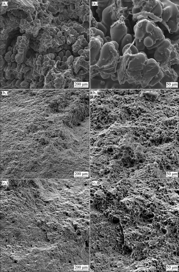
Fig. 13 SEM images of fractured surfaces in as-cast LM13 alloy (a1, a2), FSPed specimen (b1, b2) and composite (c1, c2)
Figures 13(c1) and (c3) show the SEM images of fractured surfaces in the composite reinforced by B4C. It is expected that in composites with reinforcing particles, the number of voids and dimples would be increased. The fracture surface of the reinforced FSPed composites exhibits large number of shallower and smaller dimples. These smaller dimples are formed because of their higher hardness and strength, and thereby their lower ability to plastic deformation. These observations confirm lower ductility of reinforced FSPed composites compared with the FSPed specimens without reinforcement. Moreover, some debondings in the B4C particles and the A356 matrix interfaces can be observed in Figs. 13(c1) and (c2).
Similar to hardness, the elements improving the hardness, will improve the tensile properties as well, for the FSPed specimens with reinforcing particles. However, as cited before, an increase in w/v results in a reduction in the Si particles size, leading to tensile properties improvement. Similarly, the reinforcing particles agglomeration is reduced as the w/v rises. Therefore, it can be concluded that, in contrary to the hardness, the volume fraction of reinforcing particles is not the major factor in determining UTS value, but it is severely influenced by Si particles size and morphology as well as the reinforcing particles agglomeration.
3.5 Establishment of models using ANN
The significant influences of FSP parameters such as tool rotational and traverse speeds on the microstructure and mechanical properties of the composites are observed from experimental results. Since the limited input parameters are used in this study, it is valuable to predict the corresponding values of Si particles size, axial force, hardness and UTS for process parameters. To this aim, a feed forward neural network with back-propagation algorithm was developed to foretell the required results without performing an experiment.
To achieve the best neural network parameters (for instance, the number of hidden neurons and the activation function), several neural network architectures were considered [40,41]. The performance of each ANN was measured by mean relative error (MRE) via Eq. (5):
 (5)
(5)
where P is the number of experimental sets; xe is the experimental value; and xp is the predicted value.
According to the trial-and-error approach and the minimum MRE, the neural network with the architecture of seven-neuron hidden layer and ��logsig�� activation function for hidden and output layers were selected (Fig. 14) [24,42,43].
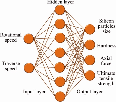
Fig. 14 Three-layer neural network used in this study
To determine the hardness, axial force, Si particles size and UTS as outputs of the models, Eqs. (6)-(9) were obtained from ANN based on the input parameters of rotational and traverse speeds. Similarly, using Eqs. (6)-(9)), hardness (H), axial force (Fa), Si particles size (DSi) and UTS (��UTS) may be calculated as follows:

 (6)
(6)

 (7)
(7)

 (8)
(8)

 (9)
(9)
where Fi (i=1, 2, 3, ��, 7) are the weights and can be calculated as follows:
 (10)
(10)
where i=1, 2,��, 7 and Ui can be determined by
 (11)
(11)
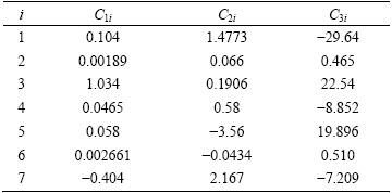
where R and T represent rotational speed and traverse speed, respectively. The constants of Cji in Eq. (11) are given in Table 2.
3.6 Multi-objective optimization
A hybrid multi-objective evolutionary algorithm was utilized to optimize the studied FSP process parameters. In the suggested method, at first a Pareto front was created by NSGA-II and then, to achieve the best compromise solution from the Pareto front, the TOPSIS was employed.
Table 2 Weights and biases between input and hidden layers for Eq. (11)
Multi-objective optimization is defined as finder of a vector of decision variables satisfying constraints to give acceptable values to all objective functions. In these problems, there are several objective functions to be optimized simultaneously. Generally, in multi-objective optimization problems, the objective functions have an opposite behavior compared with each other. This means that, an improvement in one objective function causes the other one to deteriorate. Therefore, there is no single optimal solution to be superior to all other solutions with respect to all the objective functions. Instead, there is a set of optimal non-dominated solutions which are called Pareto front. Finally, the Pareto optimal solution will involve a set of optimal solutions that cannot be improved regarding an objective unless; at least another objective becomes worsen. Thus, it can be briefly declared that the main goal for the multi-objective optimization is to find the Pareto front consisting of the non-dominated solutions and cannot lead to the improvement of all objectives simultaneously.
Some inherent properties, such as their population- based search approach, have been made the evolutionary algorithms very suitable to solve these types of optimization problems and are widely utilized to find the Pareto front set.
3.6.1 Pareto optimization of rotational and traverse speeds
To optimize the rotational and traverse speeds as FSP input parameters, the trained neural network model was put to use in a multi-objective optimization procedure. In this procedure, four conflicting objectives of hardness (H), axial force (Fa), Si particles size (DSi), and UTS (��UTS) must be simultaneously optimized with regard to the design variables. The optimization problem can be defined in the following formulation:
 (12)
(12)
In the present optimization model, an 80-indivudual population with a crossover and mutation probabilities of 0.7 and 0.08, respectively, was considered in 500 generations.
Totally, 375 solutions were achieved over the optimization process. Figure 15(a) depicts the non- dominated individuals of four-objective optimization on the plane of hardness and axial force. Similar non- dominated individuals of four-objective optimization on the other planes are shown in Figs. 15(b)-(f). If design variables (traverse and rotational speeds) are chosen from the obtained Pareto front, the result would be the best possible combination of those four objectives.
3.6.2 Best trade-off solutions using TOPSIS
In the last stage, the Pareto optimal solutions, drawn from NSGA-II, undergo the TOPSIS analysis as a multi-attribute decision analyzing method, to rank the alternatives of Pareto front. The principle of TOPSIS is based on finding the best compromise solution which is closest to the positive ideal solution (S+) and the farthest from the negative ideal solution (S-) and consists of the following steps:
1) Input an evaluation matrix (S) (the elements of S matrix are the Pareto solutions)
2) Normalize the evaluation matrix (S) using the equation below:
 (13)
(13)
where  is the normalized rating; sij is the jth objective value of the ith alternative; and m is the number of optimum values.
3) Determine the weighted normalized decision matrix by developing a set of important weights (W) as follows:
 (14)
(14)
 (15)
(15)
4) Calculate S+ and S- as follows:

 (16)
(16)
 (17)
(17)
where J1 is a set of benefit attributes and J2 is a set of cost attributes.
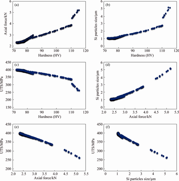
Fig. 15 Non-dominated individuals of four-objective optimization on different planes
5) Calculate the best (D+) and the worst (D-) alternatives from the positive and negative ideal solutions using the following equations:
 (18)
(18)
 (19)
(19)
6) Determine relative closeness Di for each Pareto solution as follows:
 (20)
(20)
7) Select the best compromise solution whose relative closeness (Di) is closest to 1.
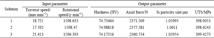
When the Pareto front is obtained, a decision maker should be employed to find a compromise solution among all non-dominated solutions. As mentioned before, this task can be done by TOPSIS method. Assigning equal weights to each objective, the solution with the highest TOPSIS score will be selected as the compromise solution. Three best solutions achieved by this procedure are shown in Table 3.
A verifying test was done to confirm the compromise solution. The optimum parameters were selected based on solution 1 of TOPSIS, but rounded to the near possible parameters available on the FSW machine to do the experiment. Therefore, the tool traverse and rotational speeds were set to 20 mm/min and 1600 r/min, respectively. The resulted values for axial force, hardness, Si particles size and UTS were 2640 N, HV 79, 1.1 ��m and 374 MPa, respectively, and thus the corresponding errors were 11%, 5.7%, 4%, and 6.3%.
Table 3 Three best solutions obtained from hybrid NSGA-II with TOPSIS
4 Conclusions
1) Threaded pin profile can uniformly disperse reinforcing particles in A356 matrix due to providing a vertical movement for the material under process.
2) Two affecting factors namely particles distribution quality and actual volume fraction of the reinforcing particles influence reversely the hardness value of composites.
3) An increase in the tool rotational speed or a decrease in tool traverse speed (increase in w/v ratio) leads to the reduction in tool axial force and Si particles size, and an improvement in UTS of the fabricated composites.
4) The composites hardness is affected by Si particles size and distribution as well as the volume fraction and dispersion of reinforcing particles. Since the volume fraction is an important affecting factor and its influence is in contrast with the other factors, the hardness variation is not constant versus the changes of w/v. With an increase in the w/v, the hardness improves firstly and then drops down.
5) Opposed to the hardness, the UTS is dominantly affected by Si particles size and distribution of reinforcing particles rather than the volume fraction of reinforcing particles. Therefore, as the w/v rises, a growth in UTS occurs due to the lower possibility of Si particle cracking and reinforcing particles agglomeration at higher w/v ratios.
6) The fracture mechanism is changed from brittle form in the as-received A356 Al alloy to ductile form in the FSPed specimen due to disruption of needle-like Si particles as well as dissolution of ��(Al) dendrites and Mg2Si phases in the metal matrix. However, in the particle reinforcd FSPed specimen due to the reduction in the plastic deformation capability, the dimples size is reduced and the specimen reveals lower ductile fracture compared with FSPed specimen without reinforcement.
References
[1] SATHISKUMAR R, MURUGAN N, DINAHARAN I, VIJAY S J. Effect of traverse speed on microstructure and microhardness of Cu/B4C surface composite produced by friction stir processing [J]. Trans Indian Inst Met, 2013, 66: 333-337.
[2] LI Y, LI Q L, LI D, LIU W, SHU G G. Fabrication and characterization of stir casting AA6061-31%B4C composite [J]. Transactions of Nonferrous Metals Society of China, 2016, 26: 2304-2312.
[3] YAO Y T, JIANG L, FU G F, CHEN L Q. Wear behavior and mechanism of B4C reinforced Mg-matrix composites fabricated by metal-assisted pressureless infiltration technique [J]. Transactions of Nonferrous Metals Society of China, 2015, 25: 2543-2548.
[4] LIU B, HUANG W M, WANG H W, WANG M L, LI X F. Compressive behavior of high particle content B4C/Al composite at elevated temperature [J]. Transactions of Nonferrous Metals Society of China, 2013, 23: 2826-2832.
[5] TUTUNCHILAR S, HAGHPANAHI M, BESHARATI GIVI M K, ASADI P, BAHEMMAT P. Simulation of material flow in friction stir processing of a cast Al-Si alloy [J]. Materials & Design, 2012, 40: 415-426.
[6] SRIVASTAVA V C, MANDAL R K, OJHA S N. Microstructure and mechanical properties of Al-Si alloys produced by spray forming process [J]. Materials Science and Engineering A, 2001, 304-306: 555-558.
[7] ALIDOKHT S A, ABDOLLAH-ZADEH A, SOLEYMANI S, SAEID T, ASSADI H. Evaluation of microstructure and wear behavior of friction stir processed cast aluminum alloy [J]. Materials Characterization, 2012, 63: 90-97.
[8] AKBARI M, KHALKHALI A, KESHAVARZ S M E, SARIKHANI E. Investigation of the effect of friction stir processing parameters on temperature and forces of Al-Si aluminum alloys [OL/J]. Journal of Materials Design and Applications, 2015.
[9] AKBARI M, KHALKHALI A, KESHAVARZ S M E, SARIKHANI E. The effect of in-process cooling conditions on temperature, force, wear resistance, microstructural, and mechanical properties of friction stir processed A356 [OL/J]. Journal of Materials Design and Applications, 2016.
[10] CHOI D H, KIM Y H, AHN B W, KIM Y I, JUNG S B. Microstructure and mechanical property of A356 based composite by friction stir processing [J]. Transactions of Nonferrous Metals Society of China, 2013, 23: 335-340.
[11] AMNE ELAHI M, SHABESTARI S G. Effect of various melt and heat treatment conditions on impact toughness of A356 aluminum alloy [J]. Transactions of Nonferrous Metals Society of China, 2016, 26: 956-965.
[12] DANG B, LIU C C, LIU F, LIU Y Z, LI Y B. Effect of as-solidified microstructure on subsequent solution-treatment process for A356 Al alloy [J]. Transactions of Nonferrous Metals Society of China, 2016, 26: 634-642.
[13] KUND N K. Influence of melt pouring temperature and plate inclination on solidification and microstructure of A356 aluminum alloy produced using oblique plate [J]. Transactions of Nonferrous Metals Society of China, 2014, 24: 3465-3476.
[14] TUTUNCHILAR S, BESHARATI GIVI M K, HAGHPANAHI M, ASADI P. Eutectic Al-Si piston alloy surface transformed to modified hypereutectic alloy via FSP [J]. Materials Science and Engineering A, 2012, 534: 557-567.
[15] AHMADKHANIHA D, ASADI P. Mechanical alloying by friction stir processing [C]//Advances in Friction Stir Welding and Processing. London: Woodhead Publishing, 2014: 387-425.
[16] DEVARAJU A, KUMAR A, KOTIVEERACHARI B. Influence of addition of Grp/Al2O3p with SiCp on wear properties of aluminum alloy 6061-T6 hybrid composites via friction stir processing [J]. Transactions of Nonferrous Metals Society of China, 2013, 23: 1275-1280.
[17] DEVARAJU A, KUMAR A, KUMARASWAMY A, KOTIVEERACHARI B. Influence of reinforcements (SiC and Al2O3) and rotational speed on wear and mechanical properties of aluminum alloy 6061-T6 based surface hybrid composites produced via friction stir processing [J]. Materials & Design, 2013, 51: 331-341.
[18] ZHANG D T, XIONG F, ZHANG W W, QIU C, ZHANG W. Superplasticity of AZ31 magnesium alloy prepared by friction stir processing [J]. Transactions of Nonferrous Metals Society of China, 2011, 21: 1911-1916.
[19] DU X H, WU B L. Using friction stir processing to produce ultrafine-grained microstructure in AZ61 magnesium alloy [J]. Transactions of Nonferrous Metals Society of China, 2008, 18: 562-565.
[20] SATHISKUMAR R, DINAHARAN I, MURUGAN N, VIJAY S J. Influence of tool rotational speed on microstructure and sliding wear behavior of Cu/B4C surface composite synthesized by friction stir processing [J]. Transactions of Nonferrous Metals Society of China, 2015, 25: 95-102.
[21] ASADI P, GIVI M K B, RASTGOO A, AKBARI M, ZAKERI V, RASOULI S. Predicting the grain size and hardness of AZ91/SiC nanocomposite by artificial neural networks [J]. Int J Adv Manuf Technol, 2012, 63: 1095-1107.
[22] BEHNAGH R A, BESHARATI GIVI M K, AKBARI M. Mechanical properties, corrosion resistance, and microstructural changes during friction stir processing of 5083 aluminum rolled plates [J]. Materials and Manufacturing Processes, 2011, 27: 636-640.
[23] RADISAVLJEVIC I, ZIVKOVIC A, RADOVIC N, GRABULOV V. Influence of FSW parameters on formation quality and mechanical properties of Al 2024-T351 butt welded joints [J]. Transactions of Nonferrous Metals Society of China, 2013, 23: 3525-3539.
[24] SHOJAEEFARD M H, BEHNAGH R A, AKBARI M, GIVI M K B, FARHANI F. Modelling and Pareto optimization of mechanical properties of friction stir welded AA7075/AA5083 butt joints using neural network and particle swarm algorithm [J]. Materials & Design, 2013, 44: 190-198.
[25] MARZBANRAD J, AKBARI M, ASADI P, SAFAEE S. Characterization of the influence of tool pin profile on microstructural and mechanical properties of friction stir welding [J]. Metall and Materi Trans B, 2014, 45: 1887-1894.
[26] SHOJAEEFARD M H, KHALKHALI A, AKBARI M, ASADI P. Investigation of friction stir welding tool parameters using FEM and neural network [J]. Journal of Materials Design and Applications, 2013, 229: 2015-2026.
[27] SHIRVANIMOGHADDAM K, KHAYYAM H, ABDIZADEH H, KARBALAEI AKBARI M, PAKSERESHT A H, ABDI F. Effect of B4C, TiB2 and ZrSiO4 ceramic particles on mechanical properties of aluminium matrix composites: Experimental investigation and predictive modeling [J]. Ceramics International, 2016, 42: 6206-6220.
[28] UTHAYAKUMAR M, ARAVINDAN S, RAJKUMAR K. Wear performance of Al-SiC-B4C hybrid composites under dry sliding conditions [J]. Materials & Design, 2013, 47: 456-464.
[29] MA Z Y, SHARMA S R, MISHRA R S. Microstructural modification of as-cast Al-Si-Mg alloy by friction stir processing [J]. Metall Mat Trans A, 2006, 37: 3323-3336.
[30] MAHMOUD T S, MOHAMED S S. Improvement of microstructural, mechanical and tribological characteristics of A413 cast Al alloys using friction stir processing [J]. Materials Science and Engineering A, 2012, 558: 502-509.
[31] SATHISKUMAR R, MURUGAN N, DINAHARAN I, VIJAY S J. Characterization of boron carbide particulate reinforced in situ copper surface composites synthesized using friction stir processing [J]. Materials Characterization, 2013, 84: 16-27.
[32] SHIRVANIMOGHADDAM K, KHAYYAM H, ABDIZADEH H, KARBALAEI AKBARI M, PAKSERESHT A H, GHASALI E. Boron carbide reinforced aluminium matrix composite: Physical, mechanical characterization and mathematical modeling [J]. Materials Science and Engineering A, 2016, 658: 135-149.
[33] ASADI P, AKBARI M, KARIMI-NEMCH H. Simulation of friction stir welding and processing [C]//Advances in Friction Stir Welding and Processing. London: Woodhead Publishing, 2014: 499-542.
[34] SHINODA T, KAWAI M. Surface modification by novel friction thermomechanical process of aluminum alloy castings [J]. Surface and Coatings Technology, 2003, 169-170: 456-459.
[35] DOLATKHAH A, GOLBABAEI P, BESHARATI GIVI M K, MOLAIEKIYA F. Investigating effects of process parameters on microstructural and mechanical properties of Al5052/SiC metal matrix composite fabricated via friction stir processing [J]. Materials & Design, 2012, 37: 458-464.
[36] SHAFIEI-ZARGHANI A, KASHANI-BOZORG S F, ZAREI-HANZAKI A. Microstructures and mechanical properties of Al/Al2O3 surface nano-composite layer produced by friction stir processing [J]. Materials Science and Engineering A, 2009, 500: 84-91.
[37] VIJAYAVEL P, BALASUBRAMANIAN V, SUNDARAM S. Effect of shoulder diameter to pin diameter (D/d) ratio on tensile strength and ductility of friction stir processed LM25AA-5%SiCp metal matrix composites [J]. Materials & Design, 2014, 57: 1-9.
[38] TAHAMTAN S, FADAVI BOOSTANI A. Microstructural characteristics of thixoforged A356 alloy in mushy state [J]. Transactions of Nonferrous Metals Society of China, 2010, 20(S3): s781-s787.
[39] ABDIZADEH H, BAGHCHESARA M A. Investigation on mechanical properties and fracture behavior of A356 aluminum alloy based ZrO2 particle reinforced metal-matrix composites [J]. Ceramics International, 2013, 39: 2045-2050.
[40] LIU J J, LI H Y, LI D W, WU Y. Application of novel physical picture based on artificial neural networks to predict microstructure evolution of Al-Zn-Mg-Cu alloy during solid solution process [J]. Transactions of Nonferrous Metals Society of China, 2015, 25: 944-953.
[41] CAI A H, XIONG X, LIU Y, AN W K, ZHOU G J, LUO Y. Compositional optimization of glass forming alloys based on critical dimension by using artificial neural network [J]. Transactions of Nonferrous Metals Society of China, 2014, 24: 1458-1466.
[42] AKBARI M, ASADI P, BESHARATI GIVI M K, KHODABANDEHLOUIE G. Artificial neural network and optimization [C]//Advances in Friction Stir Welding and Processing. London: Woodhead Publishing, 2014: 543-599.
[43] SHOJAEEFARD M, AKBARI M, ASADI P. Multi objective optimization of friction stir welding parameters using FEM and neural network [J]. Int J Precis Eng Manuf, 2014, 15: 2351-2356.
����TOPSIS�Ľ�NSGA-II���Ľ���Ħ�������Ʊ�B4C/A356���ϲ�������֯����ѧ���ܵĻ�϶�Ŀ���Ż�
Mostafa AKBARI1, Mohammad Hasan SHOJAEEFARD2, Parviz ASADI3, Abolfazl KHALKHALI1
1. School of Automotive Engineering, Iran University of Science and Technology, Tehran, Iran;
2. School of Mechanical Engineering, Iran University of Science and Technology, Tehran, Iran;
3. Faculty of Engineering, Imam Khomeini International University, Qazvin, Iran
ժ Ҫ�����ý���Ħ��������A356�Ͻ�Ϊ��������Ʊ�B4C/A356���ϲ��ϡ������˹�������(ANN)�ͷ�֧�������Ŵ��㷨-II�о����ϲ��ϵ�����֯����ѧ���ܡ����ȣ��о���ͬ�ӹ��������Ƶõĸ��ϲ��ϵ�����֯���������������Ħ�����ղ��������ͷ����ת�ٶȡ������ƶ��ٶȺ���״����Ӱ������г�ʼSi�����ijߴ硢���ϲ��ϲ���B4C��ǿ���ķ�ɢЧ����������������ø���ת/�ƶ��ٶȱȺ���������״����ͷ�ܻ�ýϺõĿ����ֲ�����ϸ��Si�����ͽ��ٵ�B4C�ž��塣��Σ�ͨ��Ӳ�Ⱥ����������о����ϲ��ϵ���ѧ���ܡ������ʾ��������Ħ�����մ�������Ʒ�Ķ��ѻ����ɴ��Զ���ת��Ϊ���Զ��ѡ���������˹������缼�������˽���Ħ�����ղ����븴�ϲ�������֯����ѧ���ܵĹ�ϵ�����ý�϶����Ա������Ƶ�NSGA-II�������������㷨�õ�����Ħ�����ղ�����Pareto���Ž⼯��
�ؼ��ʣ�����Ħ�����գ�B4C�����ϲ��ϣ���Ŀ���Ż���TOPSIS��
(Edited by Wei-ping CHEN)
Corresponding author: Mostafa AKBARI; E-mail: mr.mostafaakbari@yahoo.com
DOI: 10.1016/S1003-6326(17)60258-9
Abstract: A356 alloy was used as the base metal to produce boron carbide (B4C)/A356 composites using friction stir processing (FSP). The microstructural and mechanical properties of B4C/A356 composites were optimized using artificial neural network (ANN) and non-dominated sorting genetic algorithm-II (NSGA-II). Firstly, microstructural properties of the composites fabricated in different processing conditions were investigated. Results show that FSP parameters such as rotational speed, traverse speed and tool pin profile significantly affect the size of the primary silicon (Si) particles of the base metal, as well as the dispersion quality and volume fraction of reinforcing B4C particles in the composite layer. Higher rotational to traverse speeds ratio accompanied by threaded pin profile leads to better particles distribution, finer Si particles and smaller B4C agglomerations. Secondly, hardness and tensile tests were performed to study mechanical properties of the composites. FSP changes the fracture mechanism from brittle form in the as-received metal to very ductile form in the FSPed specimens. Then, a relation between the FSP parameters and microstructural and mechanical properties of the composites was established using ANN. A modified NSGA-II by incorporating diversity preserving mechanism called the �� elimination algorithm was employed to obtain the Pareto-optimal set of FSP parameters.
