
J. Cent. South Univ. Technol. (2009) 16: 0971-0975
DOI: 10.1007/s11771-009-0161-9
![]()
Gait simulation of new robot for human walking on sand
ZHANG Li-xun(����ѫ), WANG Ling-jun(�����), WANG Feng-liang(������), WANG Ke-kuan(���˿�)
(College of Mechanical and Electrical Engineering, Harbin Engineering University, Harbin 150001, China)
Abstract:
In order to simulate the gait of human walking on different terrains a new robot with six degrees of freedom was proposed. Based on sand bearing characteristic compliance control was introduced to control system in horizontal and vertical movement directions at the end of the robot, and position control in attitude. With Matlab/Simulink toolbox, the system control models were established, and the bearing characteristics of rigid ground, hard sand, soft sand and softer sand were simulated. The results show that 0, 0.62, 0.89 and 1.12 mm are the maximal subsidences of the four kinds of ground along the positive direction of x-axis, respectively, and 0, -0.96, -1.99 and -3.00 mm are the maximal subsidences along the negative direction of x-axis, respectively. Every subsidence along y-axis is negative, and 0, -4.12, -8.23 and -12.01 mm are the maximal subsidences of the four kinds of ground, respectively. Simulation results show that the subsidence of footboard points to inferior anterior in early stage of stand phase, while points to posterior aspect in late stage. The subsidence tends to point to posterior aspect in the whole. These results are basically consistent with the gait characteristics of human walking on sand. Gait simulation of the robot for human walking on sand is achieved.
Key words:
robot; gait simulation; sand bearing characteristic; compliance control��
1 Introduction
The new robot with six degrees of freedom (6-DOF) for gait training belongs to the field of fitness or medical machine[1-2], which can simulate gait for human walking on different terrains such as the elasto-plastic ground of sand[3]. The robot should ensure the relationship between load and subsidence. Therefore, the robot should have capacity of buffer like sand to contact environment. And the key point for realizing it is the design of the robot controller.
Recently there have been some representative robots for gait training in foreign countries, such as Hapticwalker in Germany, LOKOMAT in Switzerland and Gait Simulator in Japan. A 6-DOF robot for gait training (Hapticwalker) was co-developed by Fraunhofer IPK and Charite Hospital in Berlin in Germany, on which a programmable end-effector with characteristics of exoskeleton and treadmill was developed. With biofeedback Hapticwalker could help patients to do on-line gait analysis and offer pathological data to evaluate the effect of rehabilitation. The control strategy of Hapticwalker included position control and compliance control. Position control was suitable for patients with less serious illness to do some exercises such as going up and down the stairs[4]. While compliance control was suitable for patients with more serious illness to do strength training[5]. The future issue of Hapticwalker is to simulate different terrains combining with virtual reality and do clinical studies[6]. LOKOMAT, a rehabilitation robot designed by the Swiss Federal Institute of Technology, Switzerland, with its exoskeleton designed based on treadmill, could only do some trainings such as walking and running[7-8]. Another kind of robot for gait training was designed by researchers in Makikawa laboratory in Ritsumeikan University of Japan[9-10], which integrated technologies of robot, biological and virtual reality, and could do trainings of walking, going up and down the stairs and turning. At present there have been few researches on robot simulation of sand bearing characteristic at home and abroad.
Therefore, in this work the kinematic model of the gait training robot was given based on its structure. Bearing characteristics of footboard on sand were analyzed, and a compliance control strategy was proposed. With MATLAB/Simulink toolbox, the system control models were established and the simulation was carried out.
2 Gait training robot
2.1 Structure of robot
The gait training robot with 6-DOF can be divided into left gait mechanism and right gait mechanism symmetrically. The right one is shown in Fig.1, where joints A and C are movable joints constituted by linear module, and joint P is a rotational one that can drive the footboard. The right leg of the subject can be trained by harmonious movement of the three joints, and gait simulation for different terrains can be carried out by harmonious movement of the left gait mechanism and the right one.

Fig.1 Closed-loop diagram of right gait mechanism for robot
Gait training robot could help subjects to do some trainings, such as walking on the ground, going up and down the stairs and walking on sand. In the medical machine field, it could help patients to rehabilitate fully from bad movement state of lower limbs; and in the health field, it could help a subject to experience different terrains to enhance the effect on keeping fit.
2.2 Kinematics modeling
The closed-loop vector diagram of the right gait mechanism for the robot is given in Fig.1. In Fig.1, d1=![]() , d2=
, d2=![]() , R2=
, R2=![]() , R3=
, R3=![]() . The length of rod AB is l0, and so is that of the length of rod BC. The length of rod BP is h0, and that of rod PQ is h1. The angle for vector R2 compared with horizontal line is ��2, and that for vector R3 is ��3. The angle for rod AB compared with horizontal line is qb, and that for rod PQ compared with vector R2 is ��. The angle for footboard compared with horizontal line is ��Q and that compared with rod PQ is 90?.
. The length of rod AB is l0, and so is that of the length of rod BC. The length of rod BP is h0, and that of rod PQ is h1. The angle for vector R2 compared with horizontal line is ��2, and that for vector R3 is ��3. The angle for rod AB compared with horizontal line is qb, and that for rod PQ compared with vector R2 is ��. The angle for footboard compared with horizontal line is ��Q and that compared with rod PQ is 90?.
According to vector equation of d1+R2=R3, we have:
![]() (1)
(1)
and there exists
 (2)
(2)
Forward kinematics model is derived by Eqs.(1) and (2) as follows:
 (3)
(3)
where ![]() .
.
Then inverse kinematics model is as follows:
 (4)
(4)
3 Bearing characteristic model of footboard on sand
The mechanical properties of soil include bearing and shearing characteristics. The bearing characteristic describes the relationship between stress and strain of soil under condition that the load is vertical. REECE provided a semiempirical model of soil bearing characteristic and described the interactions between machine and soil based on theoretical analysis and lots of simulation experiments. The formula between vertical load and subsidence was arrived as follows[11-12]:
 (5)
(5)
where p is the pressure per unit area; b is the radius of the short side of a flat plate or a circular plate; n is the correction deformation index of soil; k1 is the correction cohesion deformation modulus of soil; k2 is the correction friction deformation modulus of soil; z is the subsidence; F is the vertical load on board; and A is bearing area.
n, k1 and k2 are constants that represent soil characteristics without dimension and match the relationship between load and subsidence. k1 equals zero for sand. Then, Eq.(5) can be simplified as
 (6)
(6)
The footboard is a rectangle plate with a length of 300 mm and a width of 120 mm. The angle for footboard compared with level is ��Q. z is disassembled along x-axis and y-axis shown in Fig.2. According to Eq.(6), subsidence can be arrived at:
 (7)
(7)
where zx and zy are the subsidences along x-axis and y-axis, respectively.

Fig.2 Subsidences along x-axis and y-axis of footboard on sand
4 Control strategy based on sand bearing characteristic
The end trajectory of robot is usually the stored position curve when the robot helps a subject to do trainings such as walking, going up and down the stairs[13]. However, with regard to the soft ground like sand, the relationship between load and subsidence should be considered. Accordingly, based on sand bearing characteristic a compliance control was introduced to the control system at the end of the robot in horizontal and vertical directions, and to the position control in attitude.
The control system structure based on sand bearing characteristic is shown in Fig.3, where xQ, yQ and ��Q are desired trajectories of the robot��s end created by path planning; the trajectory inputs of xi and yi are achieved by subtracting subsidences of zx and zy based on the relationship between load and subsidence from the desired trajectory of ![]() and
and ![]() along x-axis and y-axis, respectively; position inputs d1i, d2i and ��i for prismatic joints 1, 2 and rotation joint 3 are achieved by inverse kinematics model L-1, respectively; position errors are obtained by subtracting tracking curves d1, d2 and �� from d1i, d2i and ��i, respectively; G1, G2 and G�� are position controllers for the corresponding joints; M1, M2 and M�� are motors; P1 and P2 are shifting pairs, and R�� is a revolute pair; and GE is the contact environment to the
along x-axis and y-axis, respectively; position inputs d1i, d2i and ��i for prismatic joints 1, 2 and rotation joint 3 are achieved by inverse kinematics model L-1, respectively; position errors are obtained by subtracting tracking curves d1, d2 and �� from d1i, d2i and ��i, respectively; G1, G2 and G�� are position controllers for the corresponding joints; M1, M2 and M�� are motors; P1 and P2 are shifting pairs, and R�� is a revolute pair; and GE is the contact environment to the

Fig.3 Control system structure based on sand bearing characteristic
end of the robot.
Based on the control system structure and Eq.(7), positions of d1i, d2i and ��i for three joints are identified as follows:
 (8)
(8)
According to Eq.(8), position deviation is caused by the load on footboard based on the relationship between load and subsidence at the end of the robot, thus deviation from the given curve appears. The working principle is as follows.
(1) When force feedback is ignored or there is no load at the end of the robot, the system will be operated under position control, that is, F=0. In this case, the robot moves on the given trajectory according to path planning, and the gait simulation of human walking on rigid ground will be achieved.
(2) When force feedback is considered and there is a load at the end of the robot, the system will be operated under compliance control. Then, the robot will simulate walking gait on sand, that is, F��0. Two kinds of motion trajectories are combined together at the end of the robot. One is the desired trajectory motion of the footboard, the other is the subsidence motion based on the relationship between load and subsidence.
5 Simulation and analysis
5.1 System simulation model based on sand bearing characteristic
According to the system control structure and MATLAB/Simulink toolbox, the system control models are established, as shown in Fig.4. In Fig.4, Path is the path planning; Path_ni is the inverse kinematics model; Motor 1 is the model of prismatic joint 1 including its mechanism, DC electromotor model and position controller, and so is Motor 2, while Motor 3 is the model of rotation joint 3; and Sand_identity represents Eq.(7).
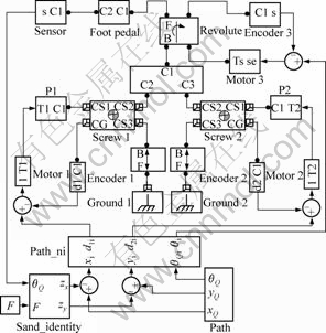
Fig.4 System simulation model based on sand bearing characteristic
5.2 Simulation and analysis
The computer for testing is the ADVANTECH type industrial computer (CPU��Intel Pentium4 2.00 GHz, memory: 1 G), and the operating system is Windows NT WorkStation 5.1(Service Pack 2).
(1) The force feedback is ignored. The robot simulates the gait of human walking on the flat rigid ground (flat ground for short) with the gait cycle of 3 s. The result is shown in Fig.5, which shows that the desired trajectory basically coincides with the tracking trajectory. Therefore, the errors of position and speed can be ignored.
(2) Force feedback is considered. The robot

Fig.5 Simulation of gait of human walking on flat ground by robot
simulates the gait of human walking on sand. Sand parameters are shown in Table 1[14-15]. Load F of foot on footboard is shown in Fig.6. The interval between points a and c is a stand phase that occupies 60% of a gait cycle. The footboard attitude is shown in Fig.7 and the attitude angle of point b is zero.
Table 1 Parameters of sand

The four kinds of gait for human walking on flat ground, hard sandy ground, soft sandy ground and softer sandy ground are simulated by the robot, and the results are curves 1-4 in Fig.8 (the attitude is not shown for easier observation), respectively. The curves of subsidence along x-axis and y-axis are shown in Fig.9. 0, 0.62, 0.89 and 1.12 mm are the maximal subsidences of the four kinds of ground along the positive direction of x-axis, respectively, and 0, -0.96, -1.99 and -3.00 mm are the maximal subsidences along the negative direction of x-axis, respectively. Every subsidence along y-axis is negative, and 0, -4.12, -8.23 and -12.01 mm are the maximal subsidences of the four kinds of ground, respectively. The interval between points a and b is in early stage of stand phase, and the subsidence of footboard points to inferior anterior, while the interval between points b and c is in late stage of stand phase and points to posterior aspect. The subsidence tends to point to posterior aspect in the whole, and the softer the sand is, the larger the subsidence is. These results are basically consistent with the gait characteristics of human walking on sand.
During the process of unloading, the return value is calculated by the relationship between load and subsidence of sand to provide subsidence space of footboard for the next cycle as the robot moves in the continuous cycle and the subsidence space of footboard is required for every cycle.

Fig.6 Relationship between load on footboard and time
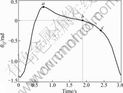
Fig.7 Relationship between attitude angle of footboard and time
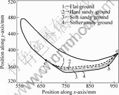
Fig.8 Gait of human walking on four kinds of ground

Fig.9 Subsidence of footboard on three kinds of ground along x-axis and y-axis
6 Conclusions
(1) A new 6-DOF robot is designed, and a control strategy of simulating sand bearing characteristic through the robot is studied. The compliance control is introduced to control system at the end of the robot in horizontal and vertical movement directions, and to position control in attitude. The simulation results verify the feasibility and effectiveness of the gait simulation for human walking on flat ground and sand.
(2) When force feedback is ignored, the robot will simulate the gait of human walking on flat rigid ground. The result shows that the desired trajectory basically coincides with the tracking trajectory. When force feedback is considered, the robot will simulate the gait of human walking on sand. The subsidence of footboard points to inferior anterior in early stage of stand phase, while it points to posterior aspect in late stage of stand phase. The subsidence tends to point to posterior aspect in the whole, and the softer the sand is, the larger the subsidence is. These results are basically consistent with the gait characteristics of human walking on sand.
(3) During the process of unloading, the return value is calculated by the relationship between load and subsidence of sand, which is the shortcoming of the system. The future issue is to simulate different terrains combined with virtual reality and do experiments.
References
[1] HESSE S, UHLENBROCK D. Mechanized gait trainer for restoration of gait[J]. Journal of Rehabilitation Research and Development, 2000, 37(6): 701-708.
[2] HESSE S, SCHMIDT H, WERNNER C. Machines to support motor rehabilitation after stroke[J]. Journal of Rehabilitation Research and Development, 2006, 43(5): 671-678.
[3] XIAO Shu-jun, CHEN Chang-fu. Mechanical mechanism analysis of tension type anchor based on shear displacement method[J]. J Cent South Univ Technol, 2008, 15(1): 106-111.
[4] SCHMIDT H, PIORKO F, BERNHARDT R, KRUQER J, HESSE S. Synthesis of perturbations for gait rehabilitation robots[C]// Proceedings of IEEE International Conference on Rehabilitation Robotics. Chicago: IEEE Press, 2005: 74-77.
[5] PATHAK P M, MUKHERJEE A, DASGUPTA A. Impedance control of space robot[J]. International Journal of Modelling and Simulation, 2006, 26(4): 316-322.
[6] HUNT K J, JACK L P, PENNYCOTT A, PERRET C, BAUMBERGER M, KAKEBEEKE T H. Control of work rate-driven exercise facilitates cardiopulmonary training and assessment during robot-assisted gait in incomplete spinal cord injury[J]. Biomedical Signal Processing and Control, 2008, 3(1): 19-28.
[7] HIDLER J M, WALL A E. Alterations in muscle activation patterns during robotic-assisted walking[J]. Clinical Biomechanics, 2005, 20(2): 184-193.
[8] TONG Xiang-qian, SHEN Ming, CHEN Gui-liang. Impedance control characteristic of active reactor[J]. Journal of Xi��an University of Technology, 2007, 23(1): 25-28. (in Chinese)
[9] TSUJI T, TANAKA Y. Tracking control properties of human-robotic systems based on impedance control[C]//Transactions on Systems, Man and Cybernetics, Part A (Systems & Humans). Hiroshima: Hiroshima University Press, 2005: 523-535.
[10] RIDDLE B, NELSON C. Impedance control for critically coupled cavities[C]//International Frequency Control Symposium and Exhibition. Vancouver: Naval Observatory, 2005: 488-493.
[11] ZHANG Ke-jian. Vehicle terramechanics[M]. Beijing: Defense Industry Press, 2002: 156-178. (in Chinese)
[12] WONG J Y, REECE A R. Prediction of rigid wheel performance based on the analysis of soil wheel stresses[J]. Journal of Terramechanics(Part I), 1967, 4(1): 81-98.
[13] CAPI G, NASU Y, BAROLLI L, MITOBE K, YAMANO M. Real time generation of humanoid robot optimal gait for going upstairs using intelligent algorithms[J]. Industrial Robot, 2001, 28(6): 489-497.
[14] THANGAVADIVELU S, TAYLOR R, CLARK S, SLOCOMBE J. Measuring soil properties to predict tractive performance of an agricultural drive tire[J]. Journal of Terramechanics, 1994, 31(4): 215-225.
[15] IAGNEMMA K, KANG S, SHIBLY H, DUBOWSKY S. Online terrain parameter estimation for wheeled mobile robots with application to planetary rovers[J]. IEEE Transactions on Robotics, 2004, 20(5): 921-927.
(Edited by CHEN Wei-ping)
Foundation item: Project(60575053) supported by the National Natural Science Foundation of China
Received date: 2009-01-22; Accepted date: 2009-03-05
Corresponding author: WANG Ling-jun, PhD; Tel: +86-13796629320; E-mail:wanglingjun@hrbeu.edu.cn
