

![]()

Trans. Nonferrous Met. Soc. China 22(2012) 2569-2577
Microstructures and formation mechanism of headstand pyrocarbon cones developed by electromagnetic-field-assisted CVD
TU Chuan-jun1,2, HUANG Qi-zhong1, ZHANG Ming-yu1, ZHAO Xin-qi2, CHEN Jiang-hua2
1. State Key Laboratory of Powder Metallurgy, Central South University, Changsha 410083, China;
2. College of Materials Science and Engineering, Hunan University, Changsha 410082, China
Received 9 July 2012; accepted 1 August 2012
Abstract:
Novel headstand pyrocarbon cones (HPCs) with hollow structure were developed on the surfaces of pyrocarbon layers of the carbon/carbon (C/C) composites at 650-750 �� by the electromagnetic-field-assisted chemical vapor deposition in the absence of catalysts. The fine microstructures of the HPCs were characterized by high-resolution transmission electron microscopy. The results show that the textural features of the HPCs directly transfer from turbostratic structure in roots to a well-ordered high texture in stems. And the degree of high texture ordering decreases gradually from the stem to the tail of the HPCs. The formation mechanism of the HPCs was inferred as the comprehensive effect of polarization induction on electromagnetic fields and particle-filler property under disruptive discharge.
Key words:
headstand pyrocarbon cones; chemical vapor deposition; electromagnetic-field-assisted method; fine microstructure; formation mechanism;
1 Introduction
The potential application of cone-shaped carbon has become a hotspot in the field of new carbon materials. The cone-shaped micro/nano carbon cone materials [1-8] are used in the scanning probe microscopy [3,4], field electron emission display [4,8,9] and many other domains of nanofabrication. For example, the graphite cone of tip with nano scale which was recently developed could take the place of the silicon or silicon nitride tip. Besides, the carbon cone with hollow structure is an ideal reservoir for liquid hydrogen. Furthermore, it could be widely used in the field of biology and chemistry [4] for its maneuverability.
Recent research has shown that the most cone-shaped carbon materials were prepared at temperature exceeding 900 �� by chemical vapor deposition (CVD) method [3-5]. The sources of the cone-shaped carbons are from manual pyrolysis material and natural materials. The natural crystal cone-shaped graphite, with height ranging from less than a micron to 40 mm, was first reported by JASZCZAK et al [7], and was determined to come from metamorphic fluids. To better solve the difficulties in practical application of carbon nanotube, many researchers have synthesized cone-shaped carbons with cone tips head outward while the root of carbon cone fixed on the substrate at a high deposition temperatures [2-5]. The crystal carbon with small-angle cone was obtained from micron bore of glass-like carbon with phenolic resin carbonized at 2000 �� by GOGOTSI et al [2]. The cone-shaped carbon possessing better field emission characteristics was obtained from carbon filaments with undiluted hydrocarbon gas as carbon source at temperature of 900-1500 �� by MURADOV and SCHWITTER [3]. Tubular graphite cones, having nano-size tips, micro-size roots and hollow interiors with a diameter ranging from about 2 nm to several tens of nanometers, were synthesized from the iron needles with N2 and CH4 using a microwave plasma assisted CVD method by ZHANG et al [4]. Recently, three unusual morphologies, i.e., a cone-shaped tip, a suddenly-shrinking tip, and a pencil point-like tip, were synthesized on a graphite rod from a mixture of graphite and silicon powder by a hydrogen arc discharge method by ZHANG et al [5]. The cone-shaped carbons with the cone tips head outward have been reported [1,4,8], but little attention has been paid to the ones with the cone tips head away from the substrates and to their formation mechanism.
In this study, novel HPCs with hollow structure were successfully developed at 650-750 �� by electromagnetic-field-assisted CVD in the absence of catalysts. It was observed that the HPCs were formed on the surfaces of pyrocarbon layers, which were deposited in advance on carbon fibers, and used as the reinforced materials to form C/C composites. Furthermore, different from the other traditional cones, the cone tip head of our HPCs with hollow structure was embedded in the substrates. In order to discuss the textural features of the HPCs and infer the formation mechanism of the HPCs, the fine microstructures of the HPCs were characterized emphatically by using transmission electron microscopy (TEM) region by region.
2 Experimental
The electric heating equipment of electromagnetic- field-assisted CVD with sandwich-structure was designed with a needle-punched carbon felt (Lanzhou Carbon Fiber Plant, China) as porous performs, and a flexible graphite sheet as conductive heating unit. The HPCs were developed on the surfaces of pyrocarbon layers of C/C composites by using C3H6 (99.9% purity) as a carbon source, and N2 and H2 as carriers, and diluent gas under the conditions as follows: the deposition temperature 650-750 ��, system gas pressure 0.2-15 kPa, gas flux 0.1-0.5 L/min, the rated power of CVD vacuum furnace 5-30 kW and within 12 h at one cycle in the absence of catalysts using a homemade depositing furnace, then followed by a heat-treatment at 2300 �� for 2-4 h to achieve the HPCs successively. The schematics of the electric heating equipment of electromagnetic- field-assisted CVD is shown in Fig. 1.
The morphology of the HPCs was observed on a scanning electron microscope (SEM; JSM-6700F) attached with energy dispersive spectroscopy (EDS). The longitudinal microstructure of the HPCs was characterized by a high-resolution transmission electron microscope (HRTEM; JEM-3010). The sample for TEM observation was prepared using focused ion beam (FIB; Nova 200/600 NanoLab). Details were as follows: First, the HPCs were fixed by Pt film as a protective coating by Pt deposition technology; second, the whole sample of the HPCs were extracted from C/C composite surface by Omiprobe equipment; then, ion beam was used to reduce the thickness of the sample. Finally, the sample was fixed by copper loop.
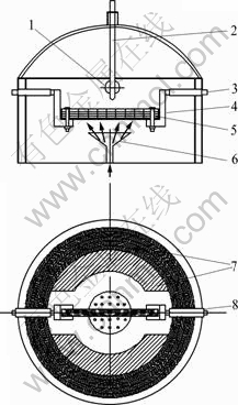
Fig. 1 Schematics of electric heating equipment of electromagnetic-field-assisted CVD: 1-Tail gas exhaust vent; 2-Thermocouple; 3-Copper electrode; 4-Graphite susceptor; 5-Electrically conductive heater (graphite sheet/carbon fiber felt); 6-Gas outlet; 7-Heat preservation felt; 8-Insulating sleeve
3 Results and discussion
3.1 Structure of HPCs
3.1.1 SEM of HPCs
Typical headstand cone morphologies and EDS analysis results of the HPCs on the surfaces of pyrocarbon layers are shown in Fig. 2. As shown in Fig. 2, the HPCs grow isolatedly on the surfaces of the pyrocarbon layers deposited in advance on carbon fibers, co-existing with hemisphere appearance (marked by solid arrow in Fig. 2(a)) and granular appearance (marked by white arrow in Fig. 2(b)). Most of the pyrocarbon cones are hollow (Figs. 2(a) and (c)) and the cone tip heads are fixed on the substrate, forming the headstand structure (Figs. 2(a), (c) and (d)). The external surfaces of some HPCs are of polygonal type (Fig. 2(c)), with irregular-shaped inner cavity. And the surfaces of some headstand cones are smooth and bright, which shows an obvious edge drape (Fig. 2(c)).
Figure 2 also shows that typical morphologies of the HPCs with stem having a minimum diameter along the growth direction of deposits are definitely different from traditional pyrocarbon and cone-shaped carbon with cone tips head outward [1,4]. Moreover, the longest outer and inner diameters of facet diagonal are about 5.0 ��m and 2.5 ��m respectively, as shown in Fig. 2(c). No catalyst was found in the HPCs by EDS (Fig. 2(e)).
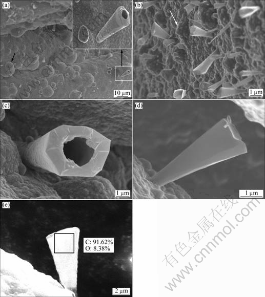
Fig. 2 Typical headstand cones morphologies and EDS analysis results of HPCs: (a) SEM image of headstand cones on surfaces of pyrocarbon layers; (b) High magnification SEM image of headstand cones on surfaces of pyrocarbon layers; (c) Top view of SEM image of single HPC; (d) Side view of SEM image of single HPC; (e) EDS analysis results of single HPC
3.1.2 TEM of HPCs
TEM images in longitudinal section of single HPCs are shown in Fig. 3. The HRTEM images and the corresponding fast Fourier transform (FFT) images in the micro-zone of the HPCs from the root to stem end to the tail of the cone region by region are shown in Fig. 4. The corresponding selected area electron diffraction (SAED) patterns of the micro-zones in Fig. 4 are shown in Fig. 5.
Figure 3 shows that the HPC is in cone-shaped hollowed structure. The fine microstructure of the HPC was examined by HRTEM at different positions. As shown in Fig. 4, from the root to stem end to the tail of the headstand cone, the HPC shows three typical textural features. In the region 1, the crystal lattice fringe of the carbon layer [10-12] has a turbostratic structure and some bends obviously. However, there are tiny regions which show ordered or short-range ordered structure. In the region 2, i.e., the transition region between the stem and the root of the HPC, there are apparent bended and twisted crystal lattice fringes. But some microcrystal states show ordered preferred orientation, which grows along the (002) direction. In regions 3 and 4, the crystal lattice fringes of the carbon layer are well-ordered and the degree of preferred orientation is comparatively high, namely, the entire field of view is a homogeneous microcrystal structure. Besides, d002 of the microcrystal is about 0.3378 nm (Fig. 4(e)). Also there are graphite- like microcrystals [13,14] which have a long-range order (Fig. 4(e)). The continuity of microcrystal states of the HPCs in the region 4 declined compared with that in the region 3. Further, FFT images [15] in regions 3 and 4 are brighter and concentrated compared with regions 1 and 2. In the region 5, the continuity of the arrangement of the crystal lattice fringes of the carbon layer and microcrystal size decreased. The crystal lattice fringes are intermittent and partially ordered, meanwhile some crystal lattice fringes slightly curve and are discontinuous (Fig. 4(a)). Therefore, the degree of preferred orientation of the carbon layer is clearly lower than that in the region 3 or 4. In the region 6, the crystal lattice fringe of the carbon layer becomes blurred, and the degree of preferred orientation is lower than that in the region 5, namely, the HPCs of the region 6 show a random orientation (Fig. 4(h)). In the region 10, the orientation of the carbon layer is disordered and non-oriented, indicating that its structure is in an amorphous structure (Fig. 4(d)). Besides, the crystal lattice fringes in the region 9, lying in the internal cone hole, are non-oriented, which is the same as that in the region 10. However, due to the Pt etching during the process of FIB sampling preparation, there are apparent dark pots of Pt particles with the diameter of 3-4 nm (Fig. 4(c)). Meanwhile, observation of the other side of the HPC reveals that the degree of preferred orientation is the same as the former side of the crystal lattice fringe of carbon layer��s microcrystal states (Figs. 4(i) and (j)).

Fig. 3 TEM images in longitudinal section of single HPC: (a) TEM image of single HPC; (b) Enlarged view of single HPC
According to Figs. 4 and 5, there are four polycrystalline diffraction rings and two sections of symmetrical diffraction arc [16] in the SAED pattern near the region 1 (Fig. 5(a)), indicating a low level of internal crystallization in roots of the HPCs. That is, the texture of the microcrystal states is in a polycrystalline structure. There are two symmetrical distributions of the selected diffraction spots in the (002) basal plane near the region 2 (Fig. 5(b)) in the SAED pattern with clear polycrystalline diffraction rings. Compared with the zone 1, the texture of the HPCs in the zone 2 shows the existence of preferred orientation along the deposition direction, referred to Fig. 4(b), in which part of the crystal lattice planes in microcrystal state has an ordered structure. The elongated diffraction spots in the (002), (004) and (006) reflection planes of the microcrystal state, which are near the region 3 (Fig. 5(c)) in the SAED pattern, are highly bright and sharp. The diffraction spots of lattice plane in the zone 3 have a great symmetry and the crystal structure is close to ideal graphite lattice [14], indicating a higher graphitization degree. In the SAED pattern which is near the region 5 (Fig. 5(e)), there are ambiguous approximately symmetrical diffraction spots along the (002) basal plane, which exhibit broadened phenomena. Also we can see several amorphous haloes, which reveal the decrease of preferred orientation degree along the (002) basal plane of carbon layer. Probably, this would be the diffraction patterns which contained at least two sets of diffraction spectra of crystallite carbon. In the SAED pattern near the region 6 (Fig. 5(e)), there are not two symmetrical distributions of the diffraction spots as the same as that in the zone 2. Instead, the diffraction spots expanded into two diffuse polycrystalline diffraction rings, which indicate the degree of preferred orientation of lattice plane in this region further declined. In the SAED near the region 10 (Fig. 5(f)), there are typical dispersive amorphous halo rings [16], indicating the characteristic of amorphous carbon in this region. Besides, the width of the diffraction arcs can directly reflect the degree of preferred orientation of graphite crystallites [17]. The angular width of the (002) diffraction arc (marked by solid arrow) in zones 2, 3 and 5 of Fig. 3, first decreased and then increased. There is a typical correlation between orientation degree of graphite crystallites and the result of SAED in the corresponding micro-zone.
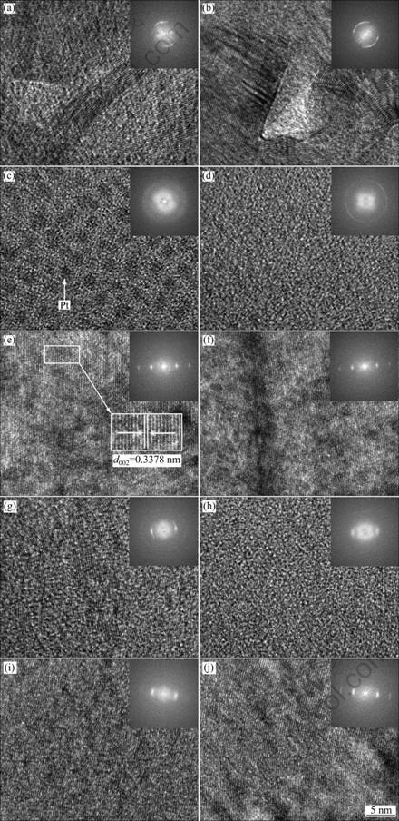
Fig. 4 HRTEM images and corresponding FFT images (entire field of view) in micro-zone of HPCs from root to stem end to tail of cone region by region in Fig. 3: (a) Zone 1; (b) Zone 2; (c) Zone 9; (d) Zone 10; (e) Zone 3; (f) Zone 4; (g) Zone 5; (h) Zone 6; (i) Zone 7; (j) Zone 8
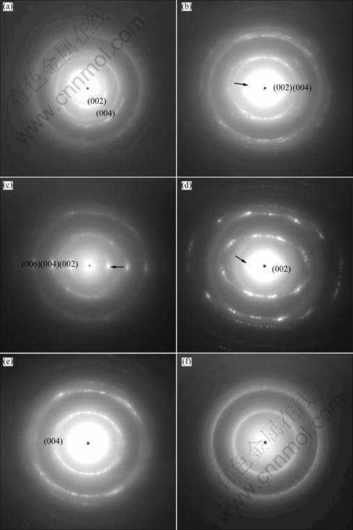
Fig. 5 Corresponding SAED pattern of micro-zone in Fig. 3: (a) Zone 1; (b) Zone 2; (c) Zone 3; (d) Zone 5; (e) Zone 6; (f) Zone 10
The results show that the HPCs, whose textural features directly transfer from turbostratic structures in roots to a well-ordered high texture in stems, were deposited on the surfaces of the pyrocarbon layers. And the degree of high texture ordering decreased gradually from the stem to the tail of the HPCs.
3.2 Formation mechanism of HPCs
3.2.1 Position of first occurrence of cone tip head
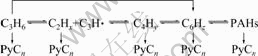
The thermal decomposition of C3H6 includes polymerization reactions of small molecules, cyclic molecules in gas phase as well as dehydrogenation aggregating into polyaromatic hydrocarbons [18-20] at the solid-gas interfaces of pyrocarbon. It is concluded that the main reaction chain [19,20] can be expressed as formula 1. The chemical bonds of reactive gas molecules would be broken to form polycyclic aromatic hydrocarbons (PAHs) and free radicals [21] on the surfaces of the pyrocarbon layers during the thermal decomposition process. And liquid droplets containing many hydrocarbons were formed due to molecular collisions [22]. The temperature was raised and strong magnetic field was generated by electric current in the C/C composites, meanwhile, the polarization effects result from strong magnetic field. These lead to form a large number of electriferous droplets and aggregates of hydrocarbon groups. Then these droplets and aggregates are polarized and then paramagnetic charged groups are formed, which can move fast under the action of electromagnetic fields and are absorbed directly into surfaces of pyrocarbon substrate. The compounds of hydrogen atom and hydrogen ion are generated from the thermal decomposition of hydrocarbon [23], and then hydrogen bubbles form in electriferous droplets. These bubbles first aggregate and merge into the liquid film when droplets spread evenly on the surface of pyrocarbon layers, then expand at an instant high temperature effect, and finally escape from weak stress area in the liquid films. As the bubbles reach a specific size, they would blast in weak stress area, so that the chemical reaction produces a bubbling effect, which would form crater-like morphology in-situ pits. Thus, the positions of the first occurrence of the cone tip head are at the roots of the HPCs.
 (1)
(1)
where x=2-4, 6; y=4, 6; C6Hz represents monocyclic aromatic hydrocarbons; PAHs represent polycyclic aromatic hydrocarbons; PyCn represents pyrolytic carbon.
3.2.2 Formation process of HPCs
The formation process of the HPCs can be inferred from the growth traces according to the fine microstructure analysis of the HPCs (Fig. 4). Two-dimensional growth models of the HPCs by electromagnetic-field-assisted CVD are shown in Fig. 6 at different stages of deposition.
In the initial growing period of the HPCs (see Fig. 6(a)), the electriferous droplets are adsorbed and condensated at the solid-gas interfaces of the pyrocarbon layers, so they can be fast-carbonized. This is mainly because the heterogeneous reactions have rapid- deposited productions under the action of the electromagnetic fields. The initial deposition process of the HPCs is coincident with the liquid droplet theory of the PAHs introduced by WU et al [24]. Then, the textural features of the HPCs directly transfer from turbostratic structures in roots to a well-ordered high texture in stems due to the influence of the transient temperature rise generated by disruptive discharge [25,26] between the active sites of crater-like pyrocarbon and electriferous droplets under electromagnetic fields (see Fig. 6(b)). According to the model of one-dimensional quantum wells [27], the deposition of electriferous droplets would be accelerated and it is more likely to form the crystallite carbon with graphite lattice at a high temperature when the disruptive discharge occurs. On the other hand, the magnetic force (F) is strong near the surface of hydrocarbon, which makes the charged polyaromatic hydrocarbons with the higher C/H density first adsorb to the active sites and pair up with small straight-chained hydrocarbon molecule [12] then deposit in stems of the HPCs. According to the formula 1, the orientation degree of graphite crystallite in the HPCs decreases gradually with increasing concentration of polyaromatic hydrocarbons and its degrees of freedom, which leads to vapor-phase nucleation [15] and physical adsorption of deposition elements. In addition, owing to the offset of magnetic field in the craters-like concave core, it cannot adsorb charged groups and just common non-polar molecules would deposit (see Fig. 6(d)).

Fig. 6 Two-dimensional growth models of HPCs by electromagnetic-field-assisted CVD at different stages of deposition: (a) Early growth stage of HPCs; (b) Middle growth stage of HPCs; (c) Top view of crater-like morphology; (d) Later growth stage of HPCs (texture image)
4 Conclusions
1) The novel HPCs were developed on the surfaces of pyrocarbon layers of the C/C composites at 650- 750 �� by electromagnetic-field-assisted CVD in the absence of catalysts.
2) The textural features of the HPCs directly transfer from turbostratic structures in roots to ordered high texture in stems. And the degree of high texture ordering decreases gradually from the stem to the tail of the HPCs.
3) The formation mechanism of the HPCs was inferred as the comprehensive effect of polarization induction on electromagnetic fields and particle-filler property under disruptive discharge for electriferous droplets and aggregates of hydrocarbon groups.
References
[1] KRISHNAN A, DUJARDIN E, TREACY M M J, HUGDAH J, LYNUM S, EBBESEN T W. Graphitic cones and the nucleation of curved carbon surfaces [J]. Nature, 1997, 388(6641): 451-454.
[2] GOGOTSI Y, LIBERA J A, KALASHNIKOV N, YOSHIMURA M. Graphite polyhedral crystals [J]. Science, 2000, 290(13): 317-320.
[3] MURADOV N, SCHWITTER A. Formation of conical carbon structures on vapor-growth carbon filaments [J]. Nano Letters, 2002, 2(6): 673-676.
[4] ZHANG G Y, JIANG X, WANG E G. Tubular graphite cones [J]. Science, 2003, 300(5618): 472-474.
[5] ZHANG Yan-li, ZHANG Li-li, HOU Peng-xiang, JIANG Hua, LIU Chang, CHENG Hui-ming. Synthesis and field emission property of carbon nanotubes with sharp tips [J]. New Carbon Materials, 2011, 26(1): 52-55.
[6] TERRONES H, HAYASHI T, MUNOZ-NAVIA M, TERRONES M, KIM Y A, GROBERT N. Graphitic cones in palladium catalysed carbon nanofibres [J]. Chemical Physics Letters, 2001, 343(3-4): 241-250.
[7] JASZCZAK J A, ROBINSON G W, DIMOVSKI S, GOGOTSI Y. Naturally occurring graphite cones [J]. Carbon, 2003, 41(11): 2085-2092.
[8] ZHANG Wei, XI Zhong-he, XUE Zeng-quan. Vertical growth of conical carbon cone with carbon nanotube core on graphite substrate [J]. Acta Physica Sinica: Overseas Edition, 2007, 56(12): 7165-7169.
[9] SAITOA Y, UEMURA S. Field emission from carbon nanotubes and its application toelectron sources [J]. Carbon, 2000, 38(2): 169-182.
[10] ZHANG Wan-hong. Calculation model of edge carbon atoms in graphite particles [J]. Transactions of Nonferrous Metals Society of China, 2011, 21(11): 2466-2475.
[11] LI Yan-wei, YIN Zhou-lan, YAO Jin-huan, ZHAO Wei-min, LIU Chang-jiu, ZHONG Sheng-kui. Electrochemical performance of nickel hydroxide doped with multi-wall carbon nanotubes [J]. Transactions of Nonferrous Metals Society of China, 2010, 20(s1): s249-s252.
[12] DONG G L, HUTTINGER K J. Consideration of reaction mechanisms leading to pyrolytic carbon of different texture [J]. Carbon, 2002, 40(1): 2515-2528.
[13] XIE Y G, HUANG Q Z, HUANG B Y. Preparation of high purity carbon nanospheres by the chemical reaction of calcium carbide and oxalic acid [J]. Carbon, 2009, 47(9): 2292-2295.
[14] GUELLAL M, OBERACKER R, HOFFMANN M J, ZHANG W G, HUTTINGER K J. Textures of pyrolytic carbon formed in thechemical vapor infiltration of capillaries [J]. Carbon, 2003, 41(1): 97-104.
[15] WEN K Y, MARROW T J, MARSDEN B J. The microstructure of nuclear graphite binders [J]. Carbon, 2008, 46(1): 62-71.
[16] LIANG Jia-miao, ZHOU Geng-heng, HE Lian-long. Micro- and nano-structural investigations of C/C composites [J]. New Carbon Materials, 2008, 23(1): 69-74.
[17] LEI Bao-ling, HE Lian-long, YI Mao-zhong, RAN Li-ping, XU Hui-juan, GE Yi-cheng, PENG Ke. New insights into the microstructure of the friction surface layer of C/C composites [J]. Carbon, 2011, 49(13): 4554-4562.
[18] ZHANG W G, HUTTINGER K J. Chemical vapor infiltration of 2D carbon fiber preform: Kinetics of densification and carbon microstructure [J]. Carbon, 2003, 41(12): 2325-2337.
[19] BECKER A, HUTTINGER K J. Chemistry and kinetics of chemical vapor deposition of pyrocarbon ��: Pyrocarbon deposition from propylene and benzene in the low temperature regime [J]. Carbon, 1998, 36(3): 201-211.
[20] LU Cui-ying, CHENG Lai-fei, ZHANG Li-tong, ZHAO Chun-nian. Gas products and carbon deposition kinetics in chemical vapor deposition from propylene [J]. New Carbon Materials, 2010, 25(1): 35-40.
[21] ZHANG Ming-yu, WANG Li-ping, HUANG Qi-zhong, CHAI Li-yuan. Rapid chemical vapor infiltration of C/C composites [J]. Transactions of Nonferrous Metals Society of China, 2009, 19(6): 1436-1439.
[22] GRISDALE R O. The formation of black carbon [J]. J Appl Phys, 1953, 24(9): 1082-1091.
[23] REZNIK B, NORINAGA K, GERTHSEN D, DEUTSCHMANN O. The effect of cooling rate on the hydrogen release from a pyrolytic carbon coating and its resulting morphology [J]. Carbon, 2006, 44(7): 1330-1333.
[24] WU Jun-feng, BAI Shuo, LIU Shu-he, XU Hong-jun, CHENG Hui-ming. Fabrication and characterization of large isotropic pyrolytic carbons [J]. New Carbon Materials, 2006, 21(2): 119-124.
[25] MOUKENGUE I A. AC discharge current characteristics and LI flashover field intensity of water droplets on insulated solid surface [J]. Journal of Electrical Engineering, 2009, 60(1): 24-28.
[26] TAK H S, HA C S, KIM D H, LEE H J, LEE H J, KANG M C. Comparative study on discharge conditions in micro-hole electrical discharge machining of tungsten carbide (WC-Co) material [J]. Transactions of Nonferrous Metals Society of China, 2009, 19(s1): s114-s118.
[27] HINO S, OKADA Y, IWASAKI K, KIJIMA M, SHIRAKAWA H. Electronic structures of cumulene type carbyne model compounds: A typical example of one-dimensional quantum well [J]. Chemical Physics Letters, 2003, 372(1-2): 59-65.
��ų�����CVD������״�Ƚ�̿���ṹ���γɻ���
Ϳ����1,2, ������1, �����1, ������2, �½���2
1. ���ϴ�ѧ ��ĩұ������ص�ʵ���ң���ɳ 410083��
2. ���ϴ�ѧ ���Ͽ�ѧ�빤��ѧԺ����ɳ 410082
ժ Ҫ�����õ�ų�����CVD������650~750 ����¶����Ʊ��������пսṹ�ĵ�״�Ƚ�̿�����൹״�Ƚ�̿������C/C���ϲ������Ƚ�̿�ı��档���ø߷ֱ�����羵�Ե�״�Ƚ�̿���ڲ��ṹ���о�ϸ�����������������״�Ƚ�̿���ڲ�֯�����ֳ��Ӹ������ҵIJ���֯��ֱ�ӵ�����ھ�������ĸ�֯���ı仯���ƣ������侥����β������̿���ṹ���̶����͡���״�Ƚ�̿���γɻ������Ʋ�Ϊ��һ����ǿ��ų������µļ����յ�ЧӦ�ͻ����ŵ������µĿ������ЧӦ���ۺ����á�
�ؼ��ʣ���״�Ƚ�̿����ѧ�����������ų����������ṹ���γɻ���
(Edited by YANG Hua)
Foundation item: Project (2011CB605801) supported by the National Basic Research Program of China; Project (2011M500127) supported by the China Postdoctoral Science Foundation; Projects (50802115, 51102089) supported by the National Natural Science Foundation of China; Project supported by the Postdoctoral Fund of the Central South University, China
Corresponding author: HUANG Qi-zhong; Tel: +86-731-88836078; E-mail: qzhuang_csu@126.com
DOI: 10.1016/S1003-6326(11)61502-1
Abstract: Novel headstand pyrocarbon cones (HPCs) with hollow structure were developed on the surfaces of pyrocarbon layers of the carbon/carbon (C/C) composites at 650-750 �� by the electromagnetic-field-assisted chemical vapor deposition in the absence of catalysts. The fine microstructures of the HPCs were characterized by high-resolution transmission electron microscopy. The results show that the textural features of the HPCs directly transfer from turbostratic structure in roots to a well-ordered high texture in stems. And the degree of high texture ordering decreases gradually from the stem to the tail of the HPCs. The formation mechanism of the HPCs was inferred as the comprehensive effect of polarization induction on electromagnetic fields and particle-filler property under disruptive discharge.
