
Trans. Nonferrous Met. Soc. China 23(2013) 3076-3082
Desilication from titanium�Cvanadium slag by alkaline leaching
De-sheng CHEN1,2, Long-sheng ZHAO1,2, Tao QI1,2, Guo-ping HU1,2, Hong-xin ZHAO1,2, Jie LI1,2, Li-na WANG1,2
1. National Engineering Laboratory for Hydrometallurgical Cleaner Production Technology, Institute of Process Engineering, Chinese Academy of Sciences, Beijing 100190, China;
2. Key Laboratory of Green Process and Engineering, Institute of Process Engineering, Chinese Academy of Sciences, Beijing 100190, China
Received 2 May 2012; accepted 1 July 2013
Abstract:
A hydrometallurgical process for the selective removal of silicon from titanium�Cvanadium slag by alkaline leaching was investigated. X-ray diffraction, scanning electron microscopy and electron dispersive spectroscopy were used to characterize the samples. The results show that anosovite, pyroxene and metallic iron are the major components of the titanium�Cvanadium slag. Anosovite is presented in granular and plate shapes, and pyroxene is distributed in the anosovite crystals. Metallic iron is spheroidal and wrapped in anosovite. Silicon is mainly in the pyroxene, and titanium and vanadium are mainly in the anosovite. The effects of agitation speed, leaching temperature, leaching time, sodium hydroxide concentration and liquid�Csolid (L/S) mass ratio on the leaching behavior of silica from titanium�Cvanadium slag were investigated. The leaching temperature and L/S mass ratio played considerable role in the desilication process. Under the optimal conditions, 88.2% silicon, 66.3% aluminum, 27.3% manganese, and only 1.2% vanadium were leached out. The desilication kinetics of the titanium�Cvanadium slag was described by the chemical control model. The apparent activation energy of the desilication process was found to be 46.3 kJ/mol.
Key words:
desilication; titanium�Cvanadium slag; alkaline leaching; kinetics;
1 Introduction
Panzhihua titanomagnetite deposits account for more than 90% titanium and 60% vanadium reserves in China [1]. Presently, titanomagnetite concentrates in China are smelted in a blast furnace to produce vanadium-bearing cast iron and titanium slag. The obtained vanadium-bearing cast iron is in converters to yield steelmaking iron and vanadium slag [2]. The titanium slag contains 22%-25% titanium dioxide (TiO2) [3]. More than three million tons of titanium slag is produced every year. Due to the dispersed distribution of titanium components in various fine grained (<10 ��m) mineral phases with complex interfacial combination, the recovery of the titanium components is difficult [2,4]. Therefore, titanium slag results in wasted resources and pollutions to the environment. In addition, the vanadium slag with alkali additives or limestone is subjected to an oxidizing roast to transform vanadium into its soluble form. The roasted cinder product is then leached with water or weak sulfuric acid. Vanadium is deposited from the solution, either in the form of metavanadate or ammonium poly vanadate, in the presence of ammonium sulfate or as commercially pure vanadium pentoxide upon hydrolysis [5,6]. This process is costly and complicated, with a low vanadium recovery rate. Moreover, the resulting poisonous gas and water cause serious environmental pollution [7].
More than 90% of TiO2 pigment plants in China are operated using the sulfate process [8]. However, the sulfate process faces severe environmental challenges. The digestion reaction of titanium slag with concentrated sulfuric acid is highly exothermic, which can be catastrophic if not properly controlled [9]. In addition, the dilute spent acid (~20% in mass fraction) formed during hydrolysis is not recycled into the process, not only causing environmental problems, but also resulting in a waste of sulfur resource.
To utilize the titanomagnetite concentrates in China, a new process based on the novel metallurgical process for preparing TiO2 was proposed by CHEN et al [10,11].
In this process, titanomagnetite concentrates are reduced by pulverized coal at approximately 1200 ��C, followed by magnetic separation to produce iron concentrate powder and titanium�C vanadium slag. The next step is desilication from the titanium�Cvanadium slag by alkaline leaching. The obtained products are decomposed with molten NaOH salt under atmospheric pressure, forming the intermediate products. Finally, the intermediate products are converted into TiO2 and vanadium component after further treatment.
However, in the molten NaOH salt decomposition process, the silicon and the titanium�Cvanadium slag form Na2SiO3 and Na2O��Al2O3��2SiO2 with high viscosity [12,13]. The high viscosity of the products inhibits the progression of molten salt decomposition and increases the viscosity of the solution, hindering filtration and separation in the subsequent water leaching process. Therefore, removal of the silicon from the titanium�Cvanadium slag is necessary prior to the NaOH molten salt decomposition process and, simultaneously, to hinder vanadium dissolution.
Up to now, the leaching behavior of silicate from the titanium�Cvanadium slag in NaOH solution has been studied rarely. Therefore, the aim of this work is to develop a hydrometallurgical process for the selective removal of silicon from the titanium�Cvanadium slag by alkaline leaching to obtain the sample with low silica and high vanadium content. The focus of the current work is to investigate the desilication behavior of the titanium�C vanadium slag by alkaline leaching. The effects of agitation speed, leaching temperature, leaching time, sodium hydroxide concentration and the mass ratio of sodium hydroxide solution to slag on the desilication process are discussed.
2 Experimental
2.1 Materials
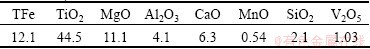
The titanium�Cvanadium slag used in this study was prepared by the direct reduction reaction and magnetic separation process [14,15]. The chemical analysis of the sample by inductively coupled plasma optical emission spectroscopy (ICP-OES, Optima 5300DV, PerkinElmer, USA) is shown in Table 1. Figure 1 shows the mineralogical analysis of the sample by XRD (Philips 1140, Cu K��, 40 mA, 30 kV), which indicates that the main crystalline phases of the sample are anosovite (MgTi2O5 and M3O5, M=Ti, Fe, Mg), metallic iron and silicon dioxide. Figure 2 shows the scanning electron microscopy-energy dispersive spectroscopy (SEM, JEOL JSM-6510A, Japan) analysis results of the polished titanium�Cvanadium slag, which show that the sample is composed of anosovite (gray), pyroxene (dark grey), and metallic iron (white). The anosovite has granular and plate shapes, and pyroxene is distributed in the anosovite crystals. The metallic iron is spheroidal, and is wrapped in anosovite. The spheroidal edge is oxidized, as shown in Fig. 2(b). Silicon is mainly in the pyroxene. Titanium and vanadium are mainly in the anosovite. All the chemical regents were of analytical grade. Deionized water was used in the experiments.
Table 1 Chemical composition of titanium-vanadium slag (mass fraction, %)

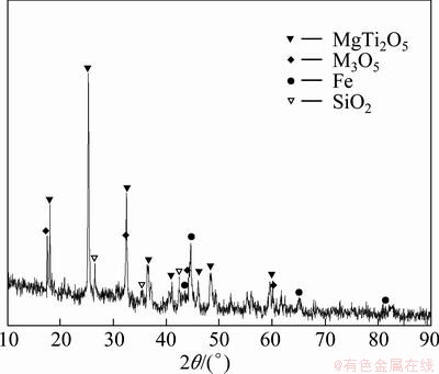
Fig. 1 XRD pattern of titanium�Cvanadium slag
2.2 Apparatus and procedure
All the experiments were conducted in batch mode. The leaching experiments were conducted in a 300 mL cylindrical stainless steel reactor. The slurry was agitated with a stainless steel bladed overhead stirrer. The reactor was heated using a hotplate equipped with a temperature control (accuracy ��2 ��C) system. A condenser with circulating ice-water was employed to minimize the evaporation of the solutions from the reactor during the experiment. The calculated sodium hydroxide solution was added to the reactor and heated to the selected temperature. When the desired temperature was reached, the titanium�Cvanadium slag was added and the reaction began. After reacting at the selected intervals, the slurry was filtered and the residue was washed with deionized water at 50 ��C for 5 min. The contents of silicon, aluminum, manganese, and vanadium in the residue were analyzed by ICP-OES. The leaching rates of rate silicon, aluminum, manganese and vanadium were calculated by the following formula:
x=(1�Cmr/ms)��100% (1)
where x is the leaching rate of silicon, aluminum, manganese or vanadium; mr is their mass in the residue; ms is their mass in the titanium�Cvanadium slag.
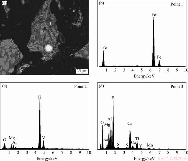
Fig. 2 SEM�CBSE image and EDS spectra of polished surfaces of titanium�Cvanadium slag
3 Results and discussion
3.1 Alkaline leaching of titanium�Cvanadium slag
3.1.1 Effect of agitation speed
The effects of agitation speed on the leaching rates of silicon, aluminum, manganese and vanadium were investigated. These experiments were performed under the following conditions: leaching temperature 110 ��C, leaching time 120 min, NaOH concentration of 40% and liquid�Csolid (L/S) mass ratio 4:1. The results are presented in Fig. 3.
It is evident from Fig. 3 that the agitation speed has a little effect on the leaching rates of silicon, aluminum, manganese and vanadium. As expected, the leaching rates of silicon, aluminum and manganese are almost independent of stirring speeds when it was higher than 400 r/min. Therefore, all experiments were carried out at a constant stirring speed of 400 r/min in the following experiments. In this case, solid particles were homogeneously suspended in the solution.
3.1.2 Effect of leaching temperature
The effects of the leaching temperature in the range
of 70-120 ��C on the leaching rates of silicon, aluminum, manganese and vanadium were investigated. In these experiments, agitation speed, leaching time, NaOH concentration and L/S mass ratio were fixed at 400 r/min, 120 min, 40% and 4:1, respectively. The results are presented in Fig. 4.
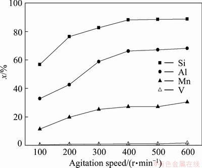
Fig. 3 Effects of agitation speed on leaching rate of silicon, aluminum, manganese and vanadium
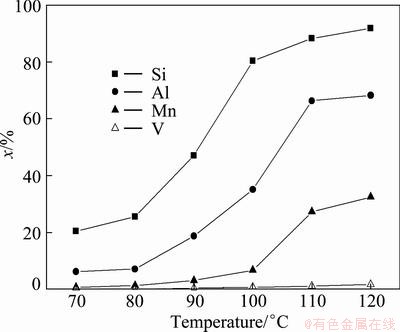
Fig. 4 Effects of leaching temperature on leaching rates of silicon, aluminum, manganese and vanadium
The leaching results in Fig. 4 show that only 20.5% silicon, 6.3% aluminum, 0.8% manganese and 0.1% vanadium are leached out at 70 ��C. With the increase of leaching temperature, the leaching rates of silicon, aluminum and manganese are also increased. When the temperature reaches 110 ��C, the 88.2%, 66.3% and 27.3% of silicon, aluminum and manganese are leached, respectively. This could be attributed to the soluble sodium silicate and sodium aluminate is easy to form with the increase of leaching temperature, but the soluble sodium vanadate is not formed in the temperature range of 70�C120 ��C [15]. There is no significant effect on the leaching when the temperature is increased further to 120 ��C. So, the optimal leaching temperature is 110 ��C.
3.1.3 Effect of leaching time
The effects of leaching time in the range of 5-120 min on the leaching rates of silicon, aluminum, manganese and vanadium were investigated under the conditions of 110 ��C, agitation speed 400 r/min, L/S mass ratio 4:1 and NaOH concentration 40%. The results are presented in Fig. 5.

Fig. 5 Effects of leaching time on leaching rates of silicon, aluminum, manganese and vanadium
The leaching results in Fig. 5 show that the leaching rate of silicon rapidly reaches 80.1% at the initial stage of the leaching process and then increases slowly. The maximum leaching rate of silicon is 88.2% at a leaching time of 120 min. The leaching rates of aluminum, manganese and vanadium increase slowly, achieving 66.3%, 27.3%, and 1.2%, respectively, at a leaching time of 120 min. So, the optimal leaching time is 120 min.
3.1.4 Effect of NaOH concentration
The effects of NaOH concentration on the leaching rates of silicon, aluminum, manganese and vanadium were studied. In this experiment, the leaching temperature was 110 ��C, leaching time was 120 min, agitation speed was 400 r/min and L/S mass ratio was 4:1. The results are presented in Fig. 6.

Fig. 6 Effects of NaOH concentration on leaching rates of silicon, aluminum, manganese and vanadium
Figure 6 shows that the leaching rates of silicon, aluminum and manganese are improved with the increase of NaOH concentration. Sodium hydroxide acts as a fluidizing and fluxing agent in the reaction. Excess sodium hydroxide is necessary to maintain the liquidity of the reactants and ensure sufficient reactions. However, the leaching rate of silicon surprisingly does not increase with the increase in NaOH concentration. Such results indicate that the rate-limiting step of the desilication reaction may be not controlled by external diffusion. This is because a higher NaOH concentration increases the viscosity of the system and the mass transfer resistance in the L/S interface. In order to investigate the other parameters, NaOH concentration of 40% is chosen.
3.1.5 Effect of L/S mass ratio
The effects of the L/S mass ratio on the leaching rate of silicon, aluminum, manganese and vanadium were investigated. In these experiments, the agitation speed, leaching temperature, leaching time and NaOH concentration were fixed at 400 r/min, 110 ��C , 120 min and 40%, respectively. The results are presented in Fig. 7.
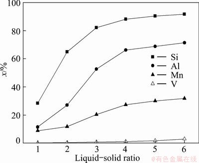
Fig. 7 Effects of L/S mass ratio on leaching rates of silicon, aluminum, manganese and vanadium
The leaching results in Fig. 7 indicate that the increase in the L/S mass ratio from 1.0 to 4.0 causes a sharp increase in the leaching rates of silicon and aluminum from 28.4% and 11.5% to 88.2% and 66.5%, respectively. This can be explained by the increase in the amount of free NaOH and lower viscosity during the reaction. No significant effects on the leaching rates of silicon and aluminum are observed when the L/S mass ratio is increased further from 4.0 to 6.0. So, the optimal L/S mass ratio is 4:1.
3.2 Kinetics analysis
Desilication of titanium�Cvanadium slag in sodium hydroxide system is a typical liquid-solid reaction, which can be analyzed with the shrinking core model [16]. According to the assumption, the particle of titanium�Cvanadium slag is spherical and the reaction between sodium hydroxide and titanium�Cvanadium slag is first-order for NaOH. The following two kinetic equations are applied to different rate-controlling step.
Chemical reaction controlled process,
1-(1-x)1/3=krt (2)
Diffusion through ash layer controlled process,
1+2(1-x)-3(1-x)2/3=kdt (3)
In the kinetics analysis experiments, the solution volume, agitation speed, leaching time, NaOH concentration and L/S mass ratio were fixed at 200 mL, 400 r/min, 40% and 4:1, respectively. The effect of leaching temperature on the silicon leaching rate is shown in Fig. 8. According to Eq. (2) and the leaching rate of silicon in Fig. 8, the values of 1-(1-x)1/3 were calculated and plotted against the respective reaction time t in Fig. 9. According to Eq. (3) and the leaching rate of silicon in Fig. 8, the values of 1+2(1-x)-3(1-x)2/3 were calculated and plotted against the respective reaction time t in Fig. 10. In the calculations, the best value of the regression coefficient correcting the rate expression is for surface control. Figure 9 gives a good linear relation for each leaching temperature, with a correlation coefficient (R2) varying from 0.996 to 0.999, which indicates that the reaction is chemically controlled.

Fig. 8 Effects of leaching temperature on leaching rate of silicon in NaOH solution
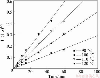
Fig. 9 Plots of 1-(1-x)1/3 versus time at different leaching temperatures
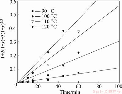
Fig. 10 Plots of 1+2(1-x)-3(1-x)2/3 versus time at different leaching temperatures
The relationship between temperature and the constant kr obtained from Eq. (2) can be expressed by the Arrhenius equation:
kr=Aexp[-Ea/(RT)] (4)
where kr is the overall rate constant, A is the frequency factor, Ea is the apparent activation energy, R is the gas constant (8.314 J/(K��mol)), and T is the leaching temperature.
Plotting the values of ln kr obtained at different leaching temperatures against 1/T gives a straight line with a correlation coefficient of 0.989 (Fig. 11). From the slope of this plot, the apparent activation energy of the desilication process of the titanium�Cvanadium slag by sodium hydroxide solution was calculated to be 46.3 kJ/mol.
3.3 Phase transformation during alkaline leaching process
In the alkaline leaching process, the titanium�C vanadium slag and the leached samples after different leaching time were analyzed by XRD and SEM. The results are shown in Figs. 12 and 13, respectively. Figure 12 shows that the intensity of SiO2 peaks becomes weak and the metallic iron is oxidized to ferriferous oxide as the leaching time increases. No new phases form during the alkaline leaching process. The final leached sample is composed of MgTi2O5, M3O5 (M=Ti, Fe, Mg), Fe, and Fe3O4, with a small amount of SiO2. Table 2 shows the chemical composition of the final leached sample. The SEM micrographs in Fig. 13 indicate that the surface of the titanium�Cvanadium slag is dense (Fig. 13(a)), and stepwise eroded by the sodium hydroxide (Figs. (b) and (c)). Finally, a porous surface is formed after the leaching reaction at 110 ��C for 120 min (Fig. 13(d)). This could be attributed to the higher concentration of NaOH, which is considered an ionized solvent.
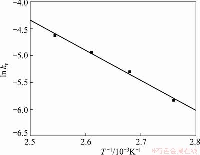
Fig. 11 Arrhenius plot of data from Fig. 9

Fig. 12 XRD patterns of samples leached at 110 ��C for different time
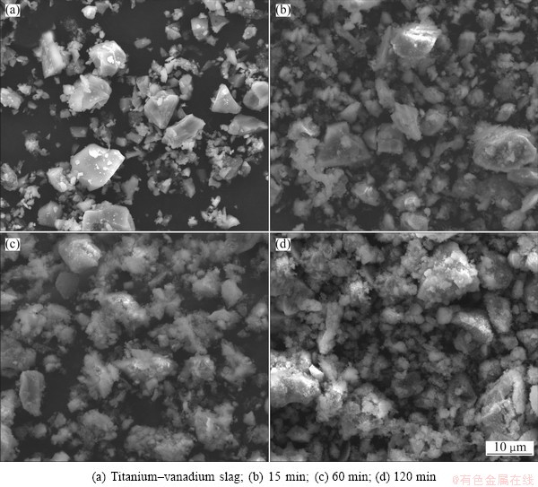
Fig. 13 SEM images of titanium�Cvanadium slag and samples leached for different time
Table 2 Chemical composition of final leached sample (mass fraction, %)
4 Conclusions
1) Anosovite, pyroxene, and metallic iron are the major components of the titanium�Cvanadium slag. Anosovite is presented in granular and plate shapes. Pyroxene is distributed in the anosovite crystals. Metallic iron is spheroidal and wrapped in anosovite, and the spheroidal edge is oxidized. Silicon is mainly in the pyroxene. Titanium and vanadium are mainly in the anosovite.
2) The leaching rate of silicon is significantly affected by the leaching temperature and L/S mass ratio. Other factors, such as agitation speed, leaching time, and NaOH concentration, also have a certain influence.
3) The optimal alkaline leaching conditions for the titanium�Cvanadium slag are as follows: leaching temperature of 110 ��C, leaching time of 120 min, NaOH concentration of 40%, and L/S mass ratio of 4:1. Under these conditions, 88.2% silicon, 66.3% aluminum, 27.3% manganese, and only 1.2% vanadium in the titanium�C vanadium slag are leached out.
4) The desilication kinetics of the titanium�C vanadium slag by alkaline leaching is described by the chemical control model. The apparent activation energy of the desilication process is 46.3 kJ/mol.
References
[1] QIU Guan-zhou, JIANG Tao, XU Jing-cang. Direct reduction of cold-bonded pellets [M]. Changsha: Central South University Press, 2001. (in Chinese)
[2] DU He-gui. Theory of smelting V and Ti-magnetite by blast furnace [M]. Beijing: Science Press, 1996. (in Chinese)
[3] ZHANG L, ZHANG L N, WANG M Y. Recovery of titanium compounds from molten Ti-bearing blast furnace slag under the dynamic oxidation condition [J]. Minerals Engineering, 2007, 20: 684-693.
[4] LI Liao-sha, SUI Zhi-tong. Physical�Cchemistry behavior of enrichment selectivity of TiO2 in perovskite [J]. Acta Physico Chimica Sinica, 2001, 17(9): 845-849. (in Chinese)
[5] SADYKHOV G B, KARYAZIN I A. Titanium-vanadium slags produced upon the direct reduction of iron from titanomagnetite concentrates [J]. Russian Metallurgy, 2007, 6: 447-454.
[6] YANG Shou-zhi. Extractive metallurgy of vanadium [M]. Beijing: Metallurgical Industry Press, 2010. (in Chinese)
[7] MOSKALYK R R, ALFANTAZI A M. Processing of vanadium: A review [J]. Minerals Engineering, 2003, 16: 793-805.
[8] LI C, LIANG B, GUO L H, WU Z B. Effect of mechanical activation on the dissolution of Panzhihua ilmenite [J]. Minerals Engineering, 2006, 19: 1430-1438.
[9] LIANG B, LI C, ZHANG C G, ZHANG Y K. Leaching kinetics of Panzhihua ilmenite in sulfuric acid [J]. Hydrometallurgy, 2005, 76(4): 173-179.
[10] CHEN D S, ZHAO L S, LIU Y H, WANG J C, QI T, WANG L N. A novel process for recovery of iron, titanium, and vanadium from titanomagnetite concentrates: NaOH molten salt roasting and water leaching processes [J]. Journal of Hazardous Materials, 2013, 245: 588-595.
[11] WANG Y, LI J, WANG L N, QI T, CHEN D S, WANG W J. Preparation of rutile titanium dioxide white pigment by NaOH molten salt process: The influence of doping and calcinations [J]. Chemical Engineering & Technology, 2011, 34(6): 905-913.
[12] XUE T Y. Production of titanium dioxide by decomposition of titanium slag with molten sodium hydroxide [D]. Dalian: Dalian University of Technology, 2008. (in Chinese)
[13] FENG Y. Reaction and separation process research on clean metallurgical technology of titanium dioxide with alkaline [D]. Beijing: Beijing University of Chemical Technology, 2009. (in Chinese)
[14] CHEN D S, SONG B, WANG L N, QI T, WANG Y, WANG, W J. Solid state reduction of Panzhihua titanomagnetite concentrates with pulverized coal [J]. Minerals Engineering, 2011, 24(8): 864-869.
[15] CHEN De-sheng. Research on comprehensive utilization of vanadium-bearing tianomagnetite concentrates [D]. Beijing: University of Science and Technology Beijing, 2012. (in Chinese)
[16] LEVENSPIL O. Chemical reaction engineering [M]. 3rd ed. New York: John Wiley and Sons, 1999.
����������ѹ�
�µ�ʤ1,2������ʤ1,2���� ��1,2������ƽ1,2���Ժ���1,2���� ��1,2��������1,2
1. �й���ѧԺ ���̹����о��� ʪ��ұ����������������ҹ���ʵ���ң����� 100190��
2. �й���ѧԺ ���̹����о��� ��ɫ�����빤���ص�ʵ���ң����� 100190
ժ Ҫ���о�һ��ѡ�����ѳ��������ж�������Ĺ��ա�����XRD��SEM��EDS�Է������ͼ���������Ʒ���б������������������������Ҫ����Ǻ���ʯ����ʯ�ͽ�����������ʯΪ��״�Ϳ���״���ֲ��ڻ�ʯ�У�������Ϊ���ͣ������״�������ڻ�ʯ�ͺ���ʯ�У���Ե������������Ҫ�ֲ��ڻ�ʯ�У��Ѻͷ���Ҫ�ֲ��ں���ʯ�С��Խ����ٶȡ������¶ȡ�����ʱ�䡢NaOHŨ�Ⱥ�Һ�̱ȶԽ�����Ӱ������о�����������������¶Ⱥ�Һ�̱ȶ�SiO2�Ľ������нϴ��Ӱ�죬�����ʵ�������£�Si��Al��Mn��V�Ľ����ʷֱ�Ϊ88.2%��66.3%��27.3%��1.2%������������ѹ趯��ѧ�����ܻ�ѧ��Ӧ���ƣ�����ۻ��Ϊ46.3 kJ/mol��
�ؼ��ʣ��ѹ裻�����������������ѧ
(Edited by Hua YANG)
Foundation item: Project (51090380) supported by the Major Program of the National Natural Science Foundation of China; Project (51125018) supported by the National Science Foundation for Distinguished Young Scholars of China; Projects (51374191, 51104139, 21006115) supported by the National Natural Science Foundation of China
Corresponding author: Li-na WANG; Tel: +86-10-82544848; E-mail: linawang@home.ipe.ac.cn
DOI: 10.1016/S1003-6326(13)62836-8
Abstract: A hydrometallurgical process for the selective removal of silicon from titanium�Cvanadium slag by alkaline leaching was investigated. X-ray diffraction, scanning electron microscopy and electron dispersive spectroscopy were used to characterize the samples. The results show that anosovite, pyroxene and metallic iron are the major components of the titanium�Cvanadium slag. Anosovite is presented in granular and plate shapes, and pyroxene is distributed in the anosovite crystals. Metallic iron is spheroidal and wrapped in anosovite. Silicon is mainly in the pyroxene, and titanium and vanadium are mainly in the anosovite. The effects of agitation speed, leaching temperature, leaching time, sodium hydroxide concentration and liquid�Csolid (L/S) mass ratio on the leaching behavior of silica from titanium�Cvanadium slag were investigated. The leaching temperature and L/S mass ratio played considerable role in the desilication process. Under the optimal conditions, 88.2% silicon, 66.3% aluminum, 27.3% manganese, and only 1.2% vanadium were leached out. The desilication kinetics of the titanium�Cvanadium slag was described by the chemical control model. The apparent activation energy of the desilication process was found to be 46.3 kJ/mol.
