
Trans. Nonferrous Met. Soc. China 29(2019) 338-348
Numerical simulation of dendrite growth in Ni-based superalloy casting during directional solidification process
Xue-wei YAN1, Xiong GUO2,3, Yan-ling LIU2,3, Xiu-fang GONG2,3, Qing-yan XU1, Bai-cheng LIU1
1. Key Laboratory for Advanced Materials Processing Technology, Ministry of Education, School of Materials Science and Engineering, Tsinghua University, Beijing 100084, China;
2. Dongfang Turbine Co., Ltd., Deyang 618000, China;
3. Long-life High Temperature Materials State Key Laboratory, Deyang 618000, China
Received 6 July 2017; accepted 15 March 2018
Abstract:
An understanding of dendrite growth is required in order to improve the properties of castings. For this reason, cellular automaton-finite difference (CA-FD) method was used to investigate the dendrite growth during directional solidification (DS) process. The solute diffusion model combined with macro temperature field model was established for predicting the dendrite growth behavior. Model validation was performed by the DS experiment, and the cooling curves and grain structures obtained by the experiment presented a reasonable agreement with the simulation results. The competitive growth of dendrites was also simulated by the proposed model, and the competitive behavior of dendrites with different misalignment angles was also discussed in detail. Subsequently, 3D dendrites growth was also investigated by experiment and simulation, and both were in good accordance. The influence on dendrites growth of initial nucleus was investigated by three simulation cases, and the results showed that the initial nuclei just had an effect on the initial growth stage of columnar dendrites, but had little influence on the final dendritic morphology and the primary dendrite arm spacing.
Key words:
numerical simulation; directional solidification; dendrite growth; Ni-based superalloy;
1 Introduction
Ni-based superalloy turbine blades serving under a high temperature and stress condition in the advanced gas turbine engine usually need to have high temperature fatigue resistance, creep strength, and corrosion resistance [1-5]. Directional solidification (DS) process has promoted the development of superalloy blades with single crystal (SC) or directionally solidified grains [6-8]. However, there are still several issues about the solidification defects needed to be solved, e.g., stray grains, freckles and cracking [9-12]. Over the past few decades, significant developments in understanding of microstructures have been made through rigorous theoretical models and critical experimental studies in well-characterized systems [13-15]. KURZ and FISHER [16] proposed a general framework which was related to tip radius, interface undercooling and primary arm spacing in alloy dendrite growth. This simplified model permitted a semi-quantitative prediction of the relationship between growth conditions and primary arm spacing. Subsequently, TRIVEDI and KURZ [17] systematically summarized the important aspects and theoretical models of dendrite growth.
In recent years, numerical simulation technique as a powerful tool was used to investigate the microstructure evolution during solidification process, and among various simulation methods, phase field (PF) and cellular automaton (CA) approaches developed rapidly and widely used [18-20]. PF method is primarily rooted in continuum models of phase transitions that can precisely describe the dendrites interface and detailed morphology in two and even three dimensions [21]. However, large scale dendrites growth using PF method is very difficult because of the need for enormous computational resources. CA method is another useful approach that can reveal a wide range of meso/micro scale microstructure features, and has the advantage of a larger mesh size and much higher computational efficiency compared with PF method [22,23]. Hence, it is extensively used in the investigation of multi-scale microstructure evolution in the Ni-based superalloy during DS process. Initially, RAPPAZ and GANDIN [24,25] proposed a CA model coupled with finite element (FE) method in order to simulate the grain growth during solidification. Subsequently, there have been many studies on the simulation of DS dendrite growth and its evolution behavior using CA method. WANG et al [26] developed a cellular automaton-finite difference (CA-FD) model to simulate solute diffusion controlled solidification of binary alloys, and found that perturbations significantly reduce the range of stable primary dendrite spacing. Recently, ZHANG and XU [27] presented a coupled directional dendrite growth model to realize the multi-scale simulation based on the CA-FD model considering macro DS parameters. However, most of studies mentioned above are 2D or pseudo 3D simulation due to the limitation of calculation capability. Although some techniques such as the parallel computing and adaptive mesh refinement methods have been developed in order to enhance computational efficiency, large scale or 3D dendrite growth simulation is still a challenge.
In this work, the solute diffusion model coupled with macro temperature field and meso grain structure model [28] is established to investage the microstructure evolution in Ni-based superalloy during DS process. The validation expriment is also performed in a Bridgman furnace, and the schematic illustration is shown in Fig. 1. In the real HRS process, the ceramic mold containing B-type thermocouples is withdrawn from the heating zone through a baffle down to the cooling zone, forming a vertical temperature gradient. Cooling curves and grain structures obtained by the experimental results are used to verify the simulation results. Finally, the competitve growth of dendrites and the influnce on 3D dendrites growth and dendrite arm spacing of initial nuclei are also investigated with the macro simulation.
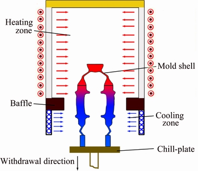
Fig. 1 Schematic illustration of Bridgman furnace
2 Mathematical models and experimental details
2.1 Temperature field model
The energy conservation equation and boundary condition equation during DS process are described as follows:
 (1)
(1)
where T is the temperature, t is the time, �� is the density, cp is the specific heat capacity, ��H is the latent heat, �� is the heat conductivity, fS is the solid fraction, and QR is the heat exchange between the casting surface and the environment.
2.2 Grain structure model
The grain structure simulation is based on the modified CA method [28]. A stochastic nucleation model was established to calculate the nucleus number as follows:
 (2)
(2)
where N is the nucleus density, ��T is the undercooling, Ns is the maximum nucleus density, ��T�� is the standard deviation of the distribution, and ��TN is the average nucleation undercooling. Then, the grain density can be described as follows:
 (3)
(3)
where ��T' is the integral unit of undercooling.
The grain growth is calculated based on the KGT equation [29], and the growth rate at the grain tip, V(��T), can be described as follows:
 (4)
(4)
where �� and �� are the grain growth coefficients.
2.3 Solute diffusion coupling with temperature field
Solute diffusion within the entire domain is then calculated coupled with the temperature field by Eq. (5) without considering nature and forced convection influence:
 (5)
(5)
where C is the composition with its subscript i denoting solid or liquid, D is the solute diffusion coefficient and k0 is the equilibrium partition coefficient. The last term on the right hand denotes the amounts of solute rejected due to the increment of solid fraction at the S/L interface.
At the interface of the liquid and solid, the partitioning of solute in the growing cell is determined by Eq. (6):
 (6)
(6)
where CS* and CL* are the average solute concentrations of the solid and liquid, respectively, in the solid at the liquid/solid interface, and k0 is the equilibrium partition coefficient.
The solute concentration, CL, in the liquid within a growing cell, is given by Eq. (7):
 (7)
(7)
where ��x is the cell size, GC is the concentration gradient at the S/L interface [26].
CL* can be determined from a linearized equilibrium phase relation:
 (8)
(8)
where C0 is the original solute concentration in the liquid, mL is the liquidus slope, T* is the actual interface equilibrium temperature, TL is the equilibrium liquidus temperature at initial solute composition, �� is the Gibbs-Thomson coefficient, �� is curvature of S/L interface and f(��i) is a anisotropy function that can be described by Eq. (9) and Eq. (10):
 (9)
(9)
 (10)
(10)
where n is the number of neighboring cells; am is the micro grid step length, and the value is 5 ��m in this work. fS(i) is the solid fraction of i cell; �� is the anisotropy coefficient, ��i is the anisotropic modulus, and for cubic crystals this value is taken as 4; ��i is the interface anisotropy angle; x, y and z are the coordinates.
By assuming that the local thermodynamic equilibrium exists at the scale of micro dendrite, a simplified and well-defined model was used to describe the temperature field in the calculation domain. For direction solidification process, adiabatic boundary was set up on both sides, as shown in Fig. 2. The cooling rate was Rc with a fixed temperature gradient G. It is assumed that the temperature was equivalent at the same micro grid, and then the temperature T(t) in the macro cell (i, j) can be simply expressed by
 (11)
(11)
where the Tliq(C0) is the liquidus temperature at initial composition C0, ��x is the cell size, and t is the solidification time.
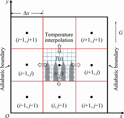
Fig. 2 Schematic illustration of coupling calculation of temperature field
2.4 Competitive growth model of dendrites
The competitive growth model for dendrites was proposed by WALTON and CHALMERS [30], as shown in Fig. 3. In DS process, the dendrites tip motion must keep up with the liquidus isotherm at the steady state. In this model, two types of dendrites are considered: favorably oriented (FO, A1 and A2) along the heat flux direction and unfavorably oriented (UO, B) whose preferential growth orientation has a �� degree with the heat flux direction. Because the growth velocity of UO dendrites, v��, is larger than that of FO dendrites, vn, it is recognized that a large growth rate corresponds to a large undercooling according to the classical dendrite growth kinetics model. The tip undercooling of the UO dendrites is higher than that of FO dendrites. Therefore, the UO dendrites should lag behind the FO dendrite tips. Accordingly, for diverging growth, the UO dendrites in Grain B cannot grow along the heat flux direction because of growth suppression by the branching FO dendrites in Grain A1 at the diverging grain boundary (GB). For converging growth, the dendrites in Grain A2 will block the dendrites growth in Grain B at the converging GB. In this case, the converging GB will be parallel to the thermal gradient direction since Grain A2 does not develop new dendrites. Consequently, UO dendrites growth is stopped by the FO grain at both types of GB. In this work, this model was also used in studies on the formation of columnar structures.
2.5 Simulation parameters and experimental methods
In this work, the superalloy employed is MM247 (Ni-8.2Cr-9.2Co-0.5Mo-9.4W-5.6Al-3.2Ta-0.7Ti-0.08C-1.1Hf, wt.%), which is a multicomponent alloy. In order to investigate the solidification process, the proposed model is effective for using the equivalent binary alloy model to simplify the real alloy. The solidification of MM247 superalloy could be regarded as a single phase (��) solidification process. Therefore, the equivalent binary Ni-X alloy was used to simulate the DS process of MM247 superalloy. Some equivalent thermophysical parameters of the Ni-X alloy were calculated by using commercial PANDAT software. However, due to the limitation of PANDAT software and issues with robustness, an optimized table-look-up technique is adopted to provide access to the data needed in the simulation. Some key thermophysical parameters of the Ni-X alloy are given in Table 1.
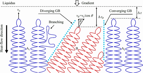
Fig. 3 Competitive growth model of dendrites
The DS experiment was performed in a Bridgman furnace, and the temperature measurement of the casting was executed during the solidification and cooling process. The casting configuration is a modified four-bar cluster mold (Fig. 4(a)), and the nominal diameter and height for each bar are 20 and 200 mm, respectively. B-type thermocouples (PtRh30-PtRh6) of the 0.2 mm in diameter were applied, and four points in the bars were selected, at the distance of 20 mm (TC I), 60 mm (TC II), 100 mm (TC III) and 150 mm (TC IV) from the casting base. The MM247 superalloy was held at 1500 ��C in a crucible, and the ceramic shell mold was placed on the chill plate in the heating chamber and was also heated up to 1500 ��C. The castings were then solidified with a withdrawal rate of 4 mm/min. After solidification and removal from the mold, one of the bars is sectioned along transverse direction and parallel to the growth direction in order to evaluate the dendrites evolution and morphologies at specific locations within the castings (Fig. 4(b)). Following metallographic preparation, polished surfaces are etched to reveal the dendritic structure using a solution containing mixed solution of 5 mL HCl, 2 mL HF, 2 g CuSO4��5H2O, and 23.5 mL H2O. Dendritic morphologies of samples are observed by using a LEICA DM6000M optical microscope and JSM-6301F field emission gun scanning electron microscope (FEG-SEM), equipped with a backscattered electrons (BSe) detector, operated at 20 kV.
Table 1 Thermophysical parameters of MM247 superalloy

3 Results and dicussion
3.1 Temperature field and grain structure

Fig. 4 Shell mold and casting
The numerical simulation and temperature measurements were carried out in order to verify the proposed model and determine the solidification time during the DS process. Figure 5 shows the simulation and exprimental results of cooling curves at different locations. The temperature distribution along the mold length was linearly decreased. The chill plate caused undercooling of the shell mold and superalloys at the distance of approximately 20 mm from the casting base, and the initial temperature was about 1350 ��C (Fig. 5(a)). The initial temperature of the other three points is about 1450, 1480 and 1490 ��C (Figs. 5(b)-(d)), respectively. It can be seen that the initial temperature in these four points were all lower than the preheating temperature. As we know, the correct value of heat transfer coefficient between the ceramic shell mold and the chill plate was crucial for the modeling processing. It caused the cooling rate of the lower part of both the mold and the casting to attain high values. The largest temperature drop of the liquid alloy occurred in the influenced area of the chill plate on the liquid alloy and the ceramic shell mold. The comparison of simulation and experimental results shows a reasonable agreement. This indicates that the proposed model for the temperature field simulation is reliable enough to serve as the foundation of microstructure simulation.

Fig. 5 Simulation and experimental results of cooling curves at different locations

Fig. 6 Simulation results
The macroscale temperature field and mesoscale grain structure provide a basic information for the microscale dendrites growth. Figure 6 shows the simulation and experimental results of temperature field and grain structure during the DS process. Simulation of temperature field distribution showed that the liquidus isotherm curve varied along the heat flux direction (Fig. 6(a)). At the initial stage, the casting was affected by the chill plate, the isotherm line was concave and the value was the minimum. Meanwhile, nuclei and small size equiaxial grains formed on the surface of chill plate which contained random crystallographic orientation in relation to the heat flux direction (Fig. 6(b)). With- drawing the ceramic shell mold from the chamber of the furnace and directional heat transfer resulted in undercooling of the next volume of liquid alloy. The continuously changed temperature distribution with different colors was observed, and the grain structures, growing along the heat flux direction, had the largest probability to sustain their further growth. Therefore, only a part of grains, orientated along the preferred directions, continued to grow. The grains without the preferred growth directions stopped to grow on the expense of columnar crystals, whose growth direction was parallel to the direction of heat flux. The competitive growth of these grains was characterized by the number of grains decreasing with an increase of the distance between the chill plate and the beginning of casting. Figures 6(c) and (d) show the simulation and experiment results of Zone I in vertical section. It was also found that the grain number and mophologies of simulation results agreed well with the experiment result.
3.2 Competitive growth of dendrites
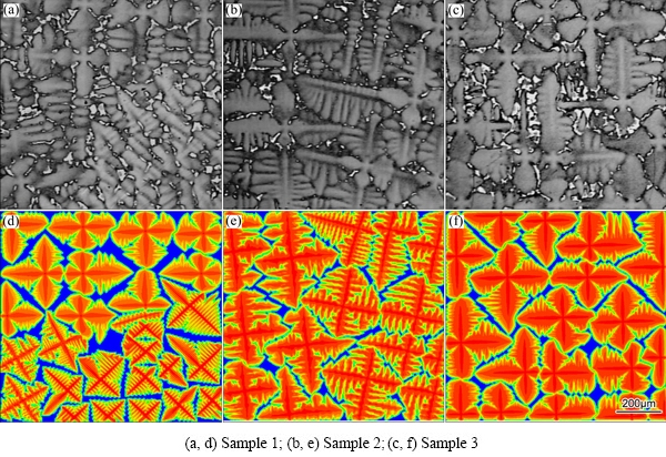
Fig. 7 Experiment (a-c) and simulation (d-f) results of dendritic morphologies in different sections
The comparison of dendritic morphologies by experiment and simulation in different sections is shown in Fig. 7. Based on the proposed model, simulation was performed in 200��200 cells with the cell size of 5 ��m without considering nature and forced convection influence. The solidification parameters such as cooling rate and temperature gradient were coupled with the simulation results of macro temperature field and grain structure, and adiabatic boundary conditions were set up on the four sides of the model. It can be seen that the secondary dendrite arms presented a four-fold symmetry of a ��cruciate flower��, and the initial tertiary dendrite arms with a random spacing grew perpendicular to the secondary arms which developed immediately behind the secondary dendrite tip. Moreover, when dendrites with different orientations encountered with each other at the boundaries of columnar grains, some branches were well developed in the free space, while some appeared competitive growth in a limited space (Figs. 7(a) and (d)). As the height of the cross section increased, grain numbers were consequently reduced due to the competitive growth, and the dendrite arm spacing increased accordingly. The solute rejected into the melt and the interaction of the solute field between the adjacent dendrites were intensified, so the tip growth of dendrites sufficiently slowed down, leading to the coarsening of the secondary dendrite arms. In addition, impingement of dendritic tips also progressively hindered the growth of dendrite arms (Figs. 7(b) and (e)). The dendrites kept competitive growing until the end of the solidification process. In Sample 3, dendrites presented the same orientation in the micro domain (Figs. 7(c) and (f)). That is because the grain size in this region was so biggish that the micro domain was covered just by one grain, and boundaries were not observed. By comparing the simulation results with the experimental results, it was found that not only the dendrite arm spacing but also the dendritic morphologies presented agreement.

Fig. 8 2D simulation results of dendrites competitive growth at different solidified time
Although the actual competitive growth is a 3D phenomenon, 2D study before the 3D study is essential for the fundamental understanding of the competitive growth of polycrystal. In order to investigate the competitive growth in the 2D polycrystal in detail, a simulation case over a large scale was performed. The computational domain size was set to be 3000��500 cells with a square mesh size of 5 ��m. Initially, the computational domain was filled with the liquid Ni-X alloy, and thirteen solid seeds with four or five dendrites were distributed on the bottom at an even interval. Some seeds had a preferred growth direction along the <100> direction, and the orientations of other seeds had a misalignment angle which varied from 5�� to 30��. The simulation parameters, i.e., the temperature gradient, was set to be 12 K/mm. Figure 8 shows the simulation results at different solidified time, and colors of the grains indicated different orientations. At the initial stage, all the dendrites could keep growing freely, and the dendritic tips were almost in the same level (Fig. 8(a)). Due to the mini-size of these dendrites, secondary arms has not developed into a length scale, so the competitive phenomenon was less obvious. As the solidification process continued, one of dendrites with misalignment angles of 30�� and 25�� were blocked at 10 s (Fig. 8(b)), and others kept growing easily. At the solidified time of 15 s, two other dendrites with misalignment angles of 20�� and 15�� were also observed to be blocked (Fig. 8(c)). For the grains with misalignment angles of 10�� and 5��, the blocking phenomenon occurred at 20 s and 30 s, respectively (Figs. 8(d) and (f)). Namely, the time at which the blocking occurred got delayed with decreasing of misalignment angle. Hence, misalignment angles have a significantly influence on the competitive growth of dendrites. In the case of a larger misalignment angle, the competitive phenomenon started quickly at the grain boundaries (Fig. 8(c)), and the secondary arms were luxuriant and branched at the diverging GB. In addition, the dendrites with red color were complete blocked by the adjacent grains at 30 s, and they would be eliminated in the further solidification process. In this simulation case, it was not observed because of the limits of computational domain. Moreover, some other parameters also have an important influence on the competitive growth of dendrites, such as cooling rate, and temperature gradients, and they will be discussed in the future work.
3.3 3D dendrites growth
In order to investigate the 3D behavior of dendrites growth in DS process, SEM technique was used to observe the dendritic morphology. Figure 9(a) shows a 3D SEM micrograph obtained from the upper end of the casting, where the solidifying material has run out of interdendritic melt material and free standing dendrites can be seen without metallographic preparation [27]. It was observed that four secondary dendrite arms emanated from the central primary dendrite, which show an un-strict four-fold symmetry, and the tertiary dendrite has not grown to a significant length. In addition, it was suggested that the primary dendrite arm spacing was close to 300 ��m. Figure 9(b) shows the corresponding simulation result from the top view. The computational domain was a 400��400��800 cells cuboid with the cell size of 5 ��m, and the simulation parameters, such as withdrawal rate and initial temperature were set according to the real experiment. It was found that the simulation result presented well agreement with the experimental result, not only the dendritic morphology, but also the size and number of dendrites. Hence, the proposed model can reproduce a wide range of other simulation cases during DS process.
The DS dendrites growth simulations with 1, 5 and 100 initial nuclei were performed and the simulation results are shown in Fig. 10. The computational domain was a 300��300��800 cells cuboid with the cell size of 5 ��m, and the solidification conditions were the same in all the three cases (a thermal gradient of 12 K/mm, and a cooling rate of 1.8 K/s). For one initial seed, it can be clearly seen that a typical cross-shaped solidification structure preferentially grew along the <100> directions (Fig. 10(a1)). The dendrites grew freely, and the primary trunk of dendrites became coarse accompanied by side branching (Fig. 10(a2)). Then, as seen in Fig. 10(a3), the solid also grew in the diagonal directions, so well-arranged primary arms completely covered the bottom surface. As the solidification proceeded, more and more secondary dendrites emanated from the primary arms, resulting in severe competitive growth (Fig. 10(a4)). The uneven fluctuation of temperature and components led to dendrites with preferred orientation growing quickly, and the others being blocked and eventually eliminated, and the dendrite arm spacing was adjusted accordingly. Finally, the dendrites grew stably and the dendrite arm spacing was equally distributed, as shown in Fig. 10(a5). It could be seen that this solidification process roughly experienced four stages: free growth, dendrites branching, competitive growth and stable growth. The dendrites growth processes for five initial nuclei were similar to those with one initial seed (Figs. 10(b1-b5)). The only difference was that the solid grew in the central and the diagonal positions simultaneously for five initial nuclei. However, for 100 initial nuclei, it was difficult to see the ��cruciate flower�� of single dendrite in Fig. 10(c1), because numerous dendrites cannot grow freely in a narrow space, and the competitive growth was earlier. Then, as shown in Figs. 10(c2, c3), the primary dendrite arms were gradually coarsened accompanied by branching and crashing of secondary dendrite arms. Therefore, the initial nucleation density just had an effect on the initial growth stage of columnar dendrites, but had little influence on the final dendritic morphology and the primary dendrite arm spacing.
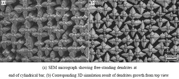
Fig. 9 Experimental and simulation results of 3D dendritic morphologies
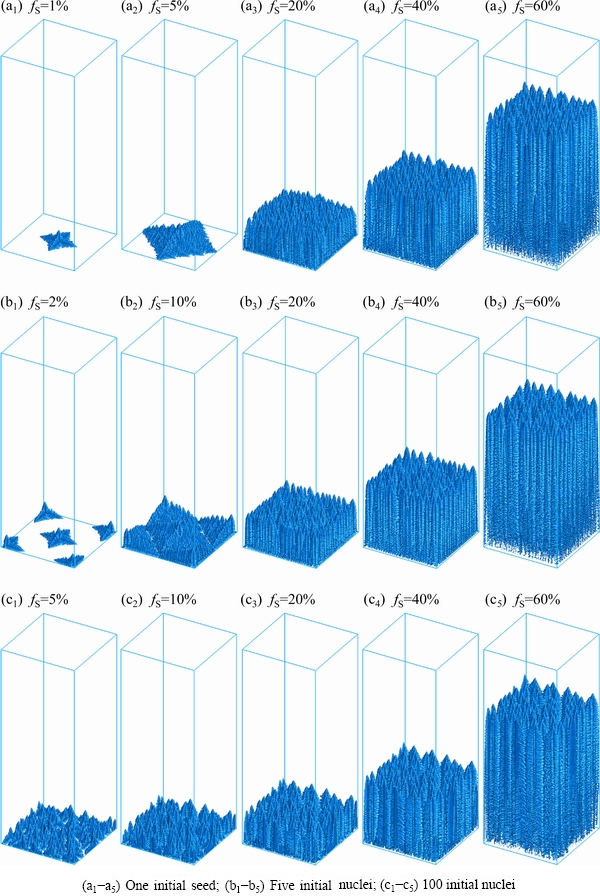
Fig. 10 Simulation results of directional dendrites growth for different initial nuclei
4 Conclusions
(1) The solute diffusion model was built coupled with macro temperature field model to realize multi-scale simulation of microstructure evolution. DS experiment was performed in a Bridgman furnace, and the cooling curves and grain structures were used to verify the accuracy of the proposed model. The experimental results presented a reasonable accordance with the simulation results.
(2) The competitive growth of dendrites was investigated by the developed model. Initial nuclei with different misalignment angles from 5�� to 30�� were also discussed. The results showed that the time at which the blocking occurred got delayed with decreasing of misalignment angle.
(3) 3D dendritic morphology was observed, and the simulation results agreed well with the experimental results. Three simulation cases with different initial nuclei of 1, 5 and 100 were carried out to study the effect of nucleation density on dendrite growth. It was found that the initial nuclei just had an effect on the initial growth stage of columnar dendrites, but had little influence on the final dendritic morphology and the primary dendrite arm spacing.
References
[1] NABARRO F R N. The superiority of superalloys [J]. Materials Science and Engineering A, 1994, 184: 167-171.
[2] MONTAKHAB M, BACAK M, BALIKCI E. Low melt height solidification of superalloys [J]. Metallurgical and Materials Transactions A, 2016, 47: 3031-3039.
[3] KEAR B H, THOMPSON E R. Aircraft gas turbine materials and process [J]. Science, 1980, 208: 847-856.
[4] BOETTINGER W J, CORIELL S R, GREER A L, KARMA A, KURZ W, RAPPAZ M, TRIVEDI R. Solidification microstructures: Recent developments, future directions [J]. Acta Materialia, 2000, 48: 43-70.
[5] ASTA M, BECKERMANN C, KARMA A, KURZ W, NAPOLITANO R, PLAPP M, PURDY G, RAPPAZ M, TRIVEDI R. Solidification microstructures and solid-state parallels: Recent developments, future directions [J]. Acta Materialia, 2009, 57: 941-971.
[6] XU Q Y, ZHANG H, LIU B C. Multiscale modelling and simulation of single crystal superalloy turbine blade casting during directional solidification process [J]. China Foundry, 2014, 11: 268-276.
[7] YU J, XU Q Y, CUI K, LIU B C, KIMATSUKA A, KUROKI Y, HIRATA A. Numerical simulation of solidification process on single crystal Ni-based superalloy investment Castings [J]. Journal of Materials Science and Technology, 2007, 23: 47-54.
[8] FRANKE M M, HILBINGER R M, LOHMULLER A, SINGER R F. The effect of liquid metal cooling on thermal gradients in directional solidification of superalloys: Thermal analysis [J]. Journal of Materials Processing Technology, 2013, 213: 2081-2088.
[9] PAN D, XU Q Y, LIU B C. Modeling of grain selection during directional solidification of single crystal superalloy turbine blade castings [J]. Journal of Mineral Metals Materials Society, 2010, 62: 30-34.
[10] MA D X, BUHRIG-POLACZEK A. Some new observations on freckle formation in directionally solidified superalloy components [J]. Metallurgical and Materials Transactions B, 2012, 43: 344-353.
[11] MA D X, BUHRIG-POLACZEK A. The geometrical effect on freckle formation in the directionally solidified superalloy CMSX-4 [J]. Metallurgical and Materials Transactions A, 2014, 45: 1435-1444.
[12] QIAN X W, CUMMINS H Z. Dendritic sidebranching initiation by a localized heat pulse [J]. Physical Review Letter, 1990, 64: 3038-3042.
[13] GLICKSMAN M E, KOSS M B, BUSHNELL L T, LACOMBE J C, WINSA E A. Dendritic growth of succinonitrile in terrestrial and microgravity conditions as a test of theory [J]. ISIJ International, 1995, 35: 604-610.
[14] PAN S Y, ZHU M F. A three-dimensional sharp interface model for the quantitative simulation of solutal dendritic growth [J]. Acta Materialia, 2010, 58: 340-352.
[15] MILLER J D, POLLOCK T M. Stability of dendrite growth during directional solidification in the presence of a non-axial thermal field [J]. Acta Materialia, 2014, 78: 23-36.
[16] KURZ W, FISHER D. Dendrite growth at the limit of stability: Tip radius and spacing [J]. Acta Metallurgica, 1980, 29: 11-20.
[17] TRIVEDI R, KURZ W. Dendritic growth [J]. International Materials Reviews, 1994, 39: 49-74.
[18] TOURRET D, KARMA A. Growth competition of columnar dendritic grains: A phase-field study [J]. Acta Materialia, 2015, 82: 64-83.
[19] YU J, XU Q Y, CUI K, LIU B C. Numerical simulation of microstructure evolution based on a modified CA method [J]. Acta Metallurgica Sinica, 2007, 43: 731-738.
[20] YIN H, FELICELLI S D, WANG L. Simulation of a dendritic microstructure with the lattice Boltzmann and cellular automaton methods [J]. Acta Materialia, 2011, 59: 3124-3136.
[21] TAKAKI T, OHNO M, SHIBUTA H, SAKANE S, SHIMOKAWABE T, AOKI T. Two-dimensional phase-field study of competitive grain growth during directional solidification of polycrystalline binary alloy [J]. Journal of Crystal Growth, 2016, 442: 14-24.
[22] GANDIN C A, RAPPAZ M. A 3D cellular automaton algorithm for the prediction of dendritic grain growth [J]. Acta Materialia, 1997, 45: 2187-2195.
[23] ZHU M F, LEE S Y, HONG C P. Modified cellular automaton model for the prediction of dendritic growth with melt convection [J]. Physical Review E, 2004, 69: 1-12.
[24] RAPPAZ M, GANDIN C A. Probabilistic modelling of microstructure formation in solidification process [J]. Acta Metallurgical Materials, 1993, 41: 345-360.
[25] GANDIN C A, RAPPAZ M. A coupled finite element-cellular automaton model for the prediction of dendritic grain structures in solidification processes [J]. Acta Metallurgical Materials, 1994, 42: 2233-2246.
[26] WANG W, LEE P D, MCLEAN C. A model of solidification microstructures in nickel-based superalloys: Predicting primary dendrite spacing selection [J]. Acta Materialia, 2003, 51: 2971-2987.
[27] ZHANG H, XU Q Y. Multi-scale simulation of directional dendrites growth in superalloys [J]. Journal of Materials Processing Technology, 2016, 238: 132-141.
[28] YAN X W, TANG N, LIU X F, SHUI G Y, XU Q Y, LIU B C. Modeling and simulation of directional solidification by LMC process for nickel base superalloy casting [J]. Acta Metallurgica Sinica, 2015, 51: 1288-1296.
[29] KURZ W, GIOVANOLA B, TRIVEDI R. Theory of microstructural development during rapid solidification [J]. Acta Metallurgical, 1986, 34: 823-830.
[30] WALTION D, CHALMERS B. The origin of the preferred orientation in the columnar zone of ingots [J]. Transactions Metallurgical Society AIME, 1959, 215: 447-457.
[31] MILLER J D, POLLOCK T M. Stability of dendrite growth during directional solidification in the presence of a non-axial thermal field [J]. Acta Materialia, 2014, 78: 23-36.
�������̹������������ºϽ�������֦������ģ��
��ѧΰ1���� ��2, 3��������2, 3�����㷼2, 3��������1�����ٳ�1
1. �廪��ѧ ����ѧԺ �Ƚ���������������ص�ʵ���ң����� 100084��
2. �������ֻ�����˾������ 618000��
3. ���������²��Ϲ����ص�ʵ���ң����� 618000
ժ Ҫ�����������������Ҫ�������̹�����֦�������������˽⣬Ϊ�ˣ�������ֵģ�ⷽ���Զ�������(DS)������֦��������������ϸ�о�������������ɢ����Ϻ���¶ȳ�����Ԥ��֦�������Ķ�߶�ģ�͡����ö�������ʵ����֤ģ�͵�ȷ�ԣ���ȴ�����Լ�������ò��ʵ������ģ�����ǺϽϺá�������������ģ��ģ��֦���ľ������������۷������в�ͬ�ᾧȡ���֦���ľ���������Ϊ�������ģ���ʵ��ķ�������ά֦�������������о���ģ���ʵ�����ǺϽϺá�ͨ��3����ͬ�������о���ʼ�κ�����֦��������Ӱ�졣�о���������ʼ�κ�������״����ʼ�ε�����Ӱ��ϴ��������յ�֦����ò��һ��֦���ۼ��(PDAS)Ӱ���С��
�ؼ��ʣ���ֵģ�⣻�������̣�֦���������������ºϽ�
(Edited by Bing YANG)
Foundation item: Project (2017ZX04014001) supported by the National Science and Technology Major Project of China; Project (2017YFB0701503) supported by the National Key R&D Program of China; Project (51374137) supported by the National Natural Science Foundation of China
Corresponding author: Qing-yan XU; Tel: +86-10-62795482; E-mail: scjxqy@tsinghua.edu.cn
DOI: 10.1016/S1003-6326(19)64943-5
Abstract: An understanding of dendrite growth is required in order to improve the properties of castings. For this reason, cellular automaton-finite difference (CA-FD) method was used to investigate the dendrite growth during directional solidification (DS) process. The solute diffusion model combined with macro temperature field model was established for predicting the dendrite growth behavior. Model validation was performed by the DS experiment, and the cooling curves and grain structures obtained by the experiment presented a reasonable agreement with the simulation results. The competitive growth of dendrites was also simulated by the proposed model, and the competitive behavior of dendrites with different misalignment angles was also discussed in detail. Subsequently, 3D dendrites growth was also investigated by experiment and simulation, and both were in good accordance. The influence on dendrites growth of initial nucleus was investigated by three simulation cases, and the results showed that the initial nuclei just had an effect on the initial growth stage of columnar dendrites, but had little influence on the final dendritic morphology and the primary dendrite arm spacing.
