
J. Cent. South Univ. (2013) 20: 385�C392
DOI: 10.1007/s11771-013-1499-6

Retraction control of motorized seat belt system with linear state observer
Lee Kang-seok, Choi Chin-chul, Lee Woo-taik
Department of Control and Instrumentation Engineering, Changwon National University, Changwon 641-773, Korea
 Central South University Press and Springer-Verlag Berlin Heidelberg 2013
Abstract:
a design and verification of linear state observers which estimate state information such as angular velocity and load torque for retraction control of the motorized seat belt (MSB) system were described. The motorized seat belt system provides functions to protect passengers and improve passenger��s convenience. Each MSB function has its own required belt tension which is determined by the function��s purpose. To realize the MSB functions, state information, such as seat belt winding velocity and seat belt tension are required. Using a linear state observer, the state information for MSB operations can be estimated without sensors. To design the linear state observer, the motorized seat belt system is analyzed and represented as a state space model which contains load torque as an augmented state. Based on the state space model, a linear state observer was designed and verified by experiments. Also, the retraction control of the MSB algorithm using linear state observer was designed and verified on the test bench. With the designed retraction control algorithm using the linear state observer, it is possible to realize various types of MSB functions.
Key words:
1 Introduction
1.1 Motorized seat belt system
The seat belt system is the most representative car safety system. Car safety systems can be classified under two headings, namely, passive and active safety systems. A passive safety system can protect passengers after accidents, while an active safety system can protect passenger before accidents [1].
The motorized seat belt (MSB) system is representative of an active safety system which can protect passengers before car accidents. Recently, due to increasing interest in car safety, research to improve the traditional seat belt system to an MSB system has progressed [1�C3]. The MSB system provides functions to protect passengers and improve passenger convenience, as shown in Table 1. The pretension, dynamic support and haptic alarm are functions to prevent additional injury by car accident and to warn passengers about dangerous driving conditions. Slack removal and belt parking are functions to prevent a reduction in MSB system performance in a dangerous situation caused by slack and poor seat belt return.
The MSB functions have their own required belt tension. The required belt tension is determined by the function��s purpose. The MSB system checks the driving conditions and decides a function which is appropriate for the situation [3].
The MSB system contains an MSB body and MSB electronic control unit (ECU). The MSB body is a form of the traditional seat belt body with a DC motor. Also, the MSB body contains a clutch to hold the generated seat belt tension [1�C2]. The MSB ECU contains a micro-controller, H-bridge inverter and signal acquisition circuit for measuring the applied current and voltage of the DC motor [3]. The MSB system generates belt tension and provides various functions through the operation of the MSB ECU and DC motor.
1.2 Limitation and possibility of improvement
To realize the MSB functions in Table 1, information about the state of the MSB system is required. This information includes the seat belt winding velocity and tension of the seat belt. Measurement of this state information with sensors increases the system cost and complexity. Furthermore, it is difficult to measure the generated tension of the seat belt, though exact belt tension is a requisite bit of state information needed to realize MSB operations.
Figure 1 shows the change of state information in DC motor operation. The DC motor operation is classified by 3 sections: Section (1) is the operating start section. In this section, the DC motor current increases instantaneously when the DC motor starts operating, and decreases as the velocity of the DC motor becomes fast. The direction of initial torque is set opposite to the direction of load torque by a return spring. The load torque and current of the DC motor are increasing in section (2). Section (3) is the DC motor stall section. The current, velocity and load torque of the DC motor are steady in this section. The applied current and voltage of the DC motor are the only measurable state information of the MSB ECU. In this case, it is assumed that the MSB functions are realized with the measured application of DC motor current.
Table 1 Functions and effects of MSB system
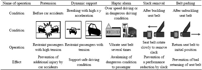
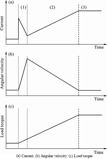
Fig. 1 Change of state information in DC motor operating:
For realizing the MSB functions with measured current, some assumptions are required, as noted below. The electrical torque of the DC motor can be represented with torque constant and the applied DC motor current as given in Eq. (1). If the angular velocity of the DC motor and its variation is zero, the DC motor load torque will be the same as the electrical torque, as given in Eqs. (2) and (3):
 (1)
(1)
 (2)
(2)
 (3)
(3)
Under these assumptions, it is possible to generate the required belt tension by regulating the applied current of the DC motor. However, these assumptions are only appropriate in the DC motor stall condition, shown in section (3). The angular velocity and its variation are not zero while the DC motor is rotating, as shown in section (1), and Fig. 1 in section (2). The calculated load torque based on the applied current of the DC motor is different from the actual generated load torque because of inertia and friction, due to the angular velocity of the DC motor [4]. Consequently, the difference between the applied current of the DC motor and the generated load torque grows when the angular velocity and its variation are high. Furthermore, when the DC motor is starting operation, as shown in section (1), it is in standby time, which means that load torque cannot be calculated based on the applied current of the DC motor, and needs to be determined, to avoid missing the actual operation of the DC motor and MSB system.
In this work, a linear state observer is designed which estimates the angular velocity and load torque of a DC motor from the applied current of the DC motor. An MSB retraction control algorithm with the designed linear state observer is also proposed for the realization of MSB functions. The designed and realized linear state observer and MSB retraction control algorithm are verified experimentally.
2 State variable model for MSB system
2.1 System modeling
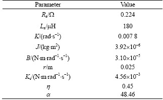
The MSB System is classified into 2 parts, as shown in Fig. 2. An electrical part represents the electrical part of the DC motor. In a mechanical part, the mechanical part of the DC motor and the MSB body are included. Also, the tension of the seat belt is represented. The parameters used in this work are shown in Table 2.
2.1.1 Electrical part
The electrical part of the MSB system is represented in Eqs. (4) and (5). The DC motor voltage equation is represented in Eq. (4) which is equivalent to the series circuit under applied voltage Va with resistance of armature winding Ra, armature current of motor La and voltage source of the back electromotive force (EMF) ea. The back EMF is related to the angular velocity of the DC motor wm as given in Eq. (2).
 (4)
(4)
 (5)
(5)
2.1.2 Mechanical part
An electrical torque of the DC motor is proportional to the applied current of the DC motor.
 (6)
(6)
 (7)
(7)
 (8)
(8)
 (9)
(9)
 (10)
(10)
 (11)
(11)
The relationship of an electrical torque te and applied current ia is shown in Eq. (6). The mechanical torque of the DC motor, inertia and friction of the mechanical part of the MSB system affect the electric torque of the DC motor te under the efficiency of the MSB system h, as shown in Eq. (7).
Additionally, the assist torque of the return spring tR and the load torque of the seat belt tL are determined as shown in Eqs. (10) and (11). The initial angle of mechanical part g and the radius of reel r are considered in Eqs. (10) and (11). Therefore, belt tension Fm can be calculated from the DC motor load torque by Eqs. (8) and (11). The seat belt winding velocity and seat belt tension, which are state information needed to realize the MSB functions, are calculated from the angular velocity and load torque of the DC motor.
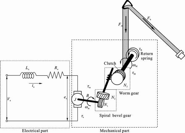
Fig. 2 Part of MSB system
Table 2 Parameters of MSB system
2.2 State variable model
The model of the MSB system is represented in Eqs. (12) and (13) and Fig. 3 from Eqs. (4) and (7):
 (12)
(12)
 (13)
(13)
Also, the models of the MSB system in Eqs. (12) and (13) are represented as state variable model, as shown in Eqs. (14)�C(19). The states of the MSB system are the applied current of the DC motor ia and the angular velocity of the DC motor wm, which is defined in Eq. (16).
 (14)
(14)
 (15)
(15)
 (16)
(16)
 (17)
(17)

 (18)
(18)
 (19)
(19)
3 Design of linear state observer
In this section, a linear state observer is designed. The type of linear state observer is a full-order observer, which can estimate not only immeasurable state information such as angular velocity or the disturbance torque of the DC motor, but also measureable state information, such as DC motor phase current [5].
3.1 State variable model with augmented state
The states of the observer are defined with the system state variable model, to design a linear state observer. It is assumed that the mechanical torque of the DC motor tm is the same as the disturbance torque of the DC motor td, and the variation of disturbance torque of the DC motor is zero. The assumptions are shown in Eqs. (20) and (21) [6�C7]:
 (20)
(20)
 (21)
(21)
According to these assumptions, the disturbance torque of the DC motor td is included in the system state variable model as an augmented state, as give in Eq. (22). The state variable model having the disturbance torque of the DC motor as an augmented state is represented in Eqs. (23) and (26):
 (22)
(22)
 (23)
(23)
 (24)
(24)
 (25)
(25)
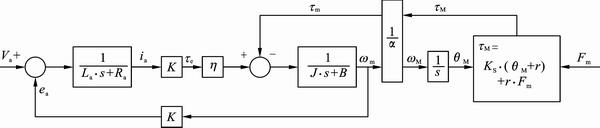
Fig. 3 MSB system modeling
 (26)
(26)
3.2 Observability
The observability matrix L0 is shown as Eq. (27). The system observability can be distinguished by analyzing the observability matrix L0 as given in Eq. (28). As a result, the MSB system is an observable system [7�C9]:
 (27)
(27)
 (28)
(28)
3.3 Design
The linear state observer is designed from the state variable model in Eqs. (22) and (26). The designed linear state observer is shown in Eqs. (29) and (30), and the result is shown in Fig. 4 [10�C12].
 (29)
(29)
 (30)
(30)
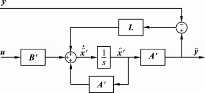
Fig. 4 Designed linear state observer
The error dynamics of the observer is represented as Eq. (31), and the characteristic equation of error dynamics is calculated as Eq. (32), which is the same as that of the observer. The feedback gain L is determined by the pole placement method [11].

 (31)
(31)
 (32)
(32)
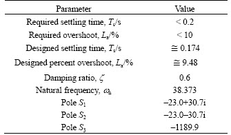
The damping ratio z and natural frequency wn, which are parameters of the response characteristic, are determined by the pole placement method. The characteristic equation of error dynamics responds as a third order system which has 3 poles, as shown in Fig. 5. The damping ratio z and natural frequency wn are determined as design constraints, as given in Table 3.
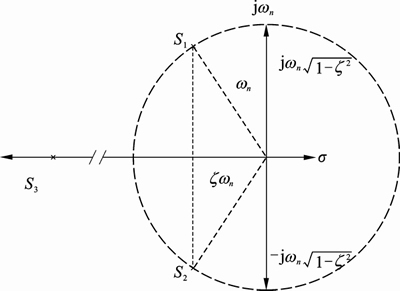
Fig. 5 Pole placement on s-plane
Table 3 Observer design parameters
3.4 Verifications
To verify the designed linear state observer, the linear state observer was implemented in the MSB ECU and tested on the test bench which is shown in Fig. 6. To verify the result of the linear state observer, various types of sensors were implemented in the test bench, such as a load cell for torque, and encoder for angular velocity of the DC motor. The applied current of the DC motor was measured by a signal acquisition circuit in the MSB ECU.
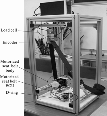
Fig. 6 Test bench
The performance of state estimation of the linear state observer was analyzed by RMSE (root mean square error) of the estimated state information based on the state information measured by sensors on the test bench. The RMSE of angular velocity of the DC motor is 62.2 rad/s. And the RMSE of the load torque of the DC motor is 8.2 mN��m. As a result, the estimated states are usable for the retraction control algorithms, as shown in Fig. 7.
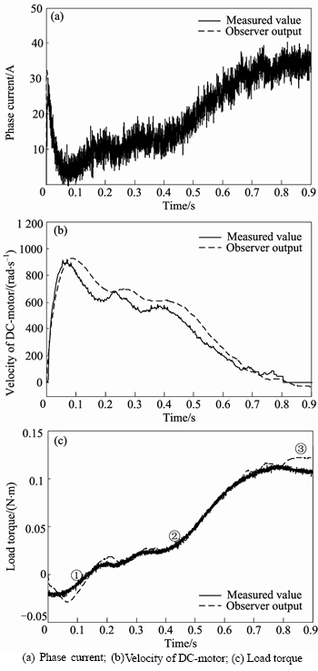
Fig. 7 Linear state observer test result:
4 Algorithm for retraction control
The MSB functions are realized with the applied current of the DC motor or the tension of seat belt causes of the DC motor; however, the generated torque causes problems, as described in section 1.2. In this section, the retraction control algorithm using a designed linear state observer is proposed.
The retraction control algorithm is shown in Fig. 8. The torque of the DC motor established by the designed linear state observer is used in the retraction control algorithm. After applying DC motor command voltage, the torque of the DC motor is estimated and compared with the required torque of the MSB function. The MSB ECU stops the DC motor from operating after satisfying the required DC motor torque.
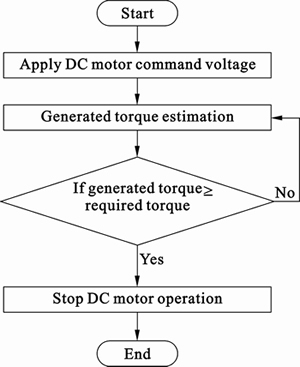
Fig. 8 Retraction control algorithm
The proposed retraction control algorithm was verified on the test bench. The operating end condition is 0.06 N��m and the operating voltage is 12 V. The result of retraction control is shown in Fig. 9.
After the DC motor is operating, the linear state observer estimates the states of applied current and load torque of the DC motor. After the estimated load torque satisfies the operation end condition, the DC motor operation is stopped by the proposed retraction control algorithm. Generated load torque is held by the clutch of the MSB body, therefore, it is possible to reduce the consumption of electric power. The result of the estimated load torque is ignored after the operating end condition. With the proposed retraction control algorithm, it is possible to generate the required load torque, which is considered to be the velocity of the DC motor, as shown in Fig. 9.
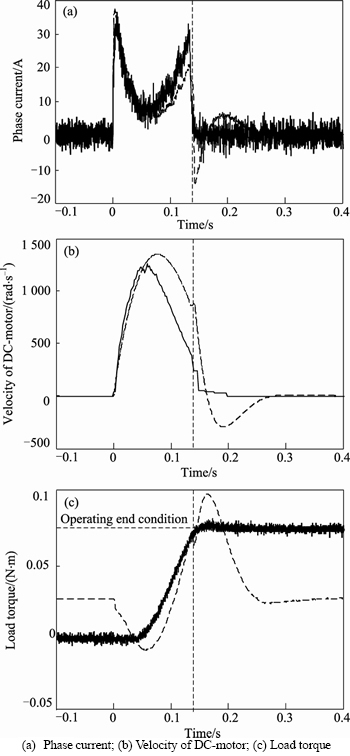
Fig. 9 Retraction control algorithm test results:
The proposed retraction control algorithm is simple to realize. By using the proposed retraction control algorithm, it is possible to determine the operating end condition without consideration of the standby time and input voltage of the DC motor.
5 Conclusions
1) State information such as seat belt winding velocity and seat belt tension are required for generating MSB functions. Measuring this state information by sensors increases the cost and complexity of the system. To solve this problem, a linear state observer has been designed. The RMSEs of the designed linear state observer, based on the state information measured by sensors on the test bench, are 62.2 rad/s for angular velocity of the DC motor and 8.2 mN��m for load torque of the DC motor, respectively. With the designed linear state observer, state information required to realize the MSB functions can be estimated without sensors.
2) Using the retraction control algorithm, it is possible to generate exact belt tension. The standby time and input voltage of the DC motor are not needed to determine the operating end condition. In addition, it is expected to reduce the consumption of electric power, by using the internal clutch of the MSB.
Nomenclature
Va:
Applied voltage, V
ia:
Armature current of DC motor, A
Ra:
Resistance of armature winding, W
La:
Inductance of armature winding, H
ea:
Counter electromotive force, V
K:
DC motor voltage constant, V/(rad��s)
Ks:
Return spring coefficient, N��m/rad
te:
Electrical torque of the DC motor, N��m
tm:
Load torque of the DC motor, N��m
tM:
Torque of the MSB mechanical part, N��m
tL:
Load torque of the seat belt, N��m
tR:
Torque of the return spring, N��m
J:
Moment of inertia, kg��m2
B:
Viscous friction constant, N��m/(rad/s)
wm:
Angular velocity of DC motor, rad/s
qm:
Angle of DC motor, rad
r:
Radius of reel, m
a:
Gear ratio of the mechanical part
h:
Efficiency of MSB system,
g:
Initial angle of mechanical part,
References
[1] Min Suk-ki, Lee Jaek-wan, Kim Byoung-soo. Development of pre-crash safety system using motorized seat belt [C]// Spring Conference, Jeongseon, 2004, 4: 1219�C1224.
[2] Park Jae-soon, Tak Tae-oh, Kim Ilh-wan, Kuk Min-gu, Kim Dae-hee, Sin Seong-eon, Kim Jung-han, Lee Dong-sub, Kim Seung-man. Driving mechanism design of a motorized seatbelt retractor[C]// KSME conference, Muju, 2006: 2951�C2956.
[3] Lee Kang-seok, Lee Woo-taik. Development of motorized seat belt control system using development-process model [C]// KSAE Conference, Seoul, 2008: 1832�C1837.
[4] Caveney D, Cooperative vehicular safety applications [J]. Control Systems, IEEE, 2010, 30: 38�C53.
[5] Luenberger D G. Observing the state of a linear system [J]. IEEE Transactions on Military Electronics, 1964, 8(2): 74�C80.
[6] Lee Sang-hun, Lee Seon-bong, Park Cheol-hu, A study on the signal processing method for the hall sensorless position control of etc system using a bldc motor [J]. Transactions of KSAE, 2008, 16(5): 92�C99.
[7] Bae Kyu-tae, Choi Chin-chul, Lee Woo-taik. Design of linear disturbance state estimator of motorized seat belt system [C]// KSAE Annual Conference, Daegu, 2010: 1993�C1998.
[8] Giuseppe S, Buja R M, Maria I V. Disturbance torque estimation in a sensorless dc drive [J]. IEEE Transactions on Industrial Electronics, 1995, 42(4): 351�C357.
[9] Jorge S, Maria I V, Carlos M. A nonlinear reduced order observer for permanent magnet synchronous motors [J]. IEEE Transactions on Industrial Electronics, 1996, 43(4): 492�C497.
[10] Metha A J, Bandyopadhyay B, Inoue A. Reduced-order observer design for servo system using duality to discrete-time sliding-surface design, ieee transactions on industrial electronics [J]. 2010, 57(11): 3793�C3800.
[11] Mutuwo T, Tomonobu S, Shinji D, Shigeru O. New sensorless control for brushless dc motors using disturbance observers and adaptive velocity estimations [J]. IEEE Transactions on Industrial Electronics, 1998, 45(2): 274�C282.
[12] Fan Shi-xun, Fan Da-peng, Hong Hua-jie, Zhang Zhi-yong. Robust tracking control for micro machine tools with load uncertainties [J]. Journal of Central South University, 2012, 19(1): 117�C127.
(Edited by HE Yun-bin)
Foundation item: Project supported by the Second Stage of Brain Korea 21 Projects and Changwon National University in 2011�C2012
Received date: 2012�C05�C31; Accepted date: 2012-12-01
Corresponding author: Lee Woo-taik, Professor, PhD; Tel: +82-55-213-3668; E-mail: wootaik@changwon.ac.kr
Abstract: a design and verification of linear state observers which estimate state information such as angular velocity and load torque for retraction control of the motorized seat belt (MSB) system were described. The motorized seat belt system provides functions to protect passengers and improve passenger��s convenience. Each MSB function has its own required belt tension which is determined by the function��s purpose. To realize the MSB functions, state information, such as seat belt winding velocity and seat belt tension are required. Using a linear state observer, the state information for MSB operations can be estimated without sensors. To design the linear state observer, the motorized seat belt system is analyzed and represented as a state space model which contains load torque as an augmented state. Based on the state space model, a linear state observer was designed and verified by experiments. Also, the retraction control of the MSB algorithm using linear state observer was designed and verified on the test bench. With the designed retraction control algorithm using the linear state observer, it is possible to realize various types of MSB functions.
