

J. Cent. South Univ. (2021) 28: 1737-1746
DOI: https://doi.org/10.1007/s11771-021-4662-5

Wheel wear comparison between motor car and trailer of intercity train
KOU Jie(�ܽ�)1, ZHANG Ji-min(�ż���)1, ZHOU He-chao(�ܺͳ�)1,WANG Cheng-ping(����Ƽ)1, SUN Li-xia(����ϼ)2
1. Institute of Rail Transit, Tongji University, Shanghai 201804, China;
2. Railway Science Technology Research and Development Center, China Academy of Railway Science Cooperation Limited, Beijing 100081, China
 Central South University Press and Springer-Verlag GmbH Germany, part of Springer Nature 2021
Abstract:
To analyze wheel wear discrepancy between motor car and trailer of an intercity train, a novel wheel wear rates calculation model was proposed, which was composed of the intercity train dynamics model, wheel-rail three-dimensional rolling contact FEM model and the wear model. The simulated results were contrasted with measured results in field test. The simulated results showed the motor car wheels had larger rotation rate and longitudinal creepage than the trailer wheels. Meanwhile, the motor car wheels encountered larger vertical forces and longitudinal forces from bogie because of the heavier car body and the impact of traction torque. The traction torque acting on motor car wheel could increase the slip rates in the rear part of wheel contact patch and weaken the spinning phenomenon of relative slip. Larger contact pressure and slip rates caused the higher wear rates of motor car wheel than those of trailer wheel. The overall trends of wheel wear depth in simulated and tested results were similar. And they both showed the motor car wheel encountered the more serious wear than the trailer wheel. These models can be used to study the effect of the traction characteristics curves on the wear of wheel.
Key words:
wheel wear; intercity train; motor car and trailer; finite element method (FEM); field test��
Cite this article as:
KOU Jie, ZHANG Ji-min, ZHOU He-chao, WANG Cheng-ping, SUN Li-xia. Wheel wear comparison between motor car and trailer of intercity train [J]. Journal of Central South University, 2021, 28(6): 1737-1746.
DOI:https://dx.doi.org/https://doi.org/10.1007/s11771-021-4662-51 Introduction
As the development of urban agglomeration, the intercity train was wildly used in recent years in China. However, the relatively small curve radius and high speed would aggravate the wheel-rail wear [1]. The wheel-rail contact is always hot spots and emphasis in the railway research field [2-6], and the wheel wear prediction is one of the directions to studying the wheel-rail contact. The wheel wear prediction model is usually composed of vehicle dynamics model, wheel-rail contact model and wheel wear model. There are two main kinds of wheel-rail contact models. The first model was proposed by KALKER [7, 8]. Kalker��s numerical implementation CONTACT and its simplified procedure FASTIM were wildly used to in the wheel-rail contact analysis [9,10]. The second model is finite element method [11, 12]. TELLISKIVI et al [13] compared the discrepancy between the model proposed by Kalker and finite element model. The result shows that when flange contact occurred, the contact characteristics results showed a significant discrepancy because the traditional method was based on the half-space assumption and did not take the plastic deformation into account [13]. DAMME et al [14] applied an arbitrary Lagrangian�CEulerian formulation to solve the wheel-rail rolling contact problem. For the wear model of wheel, PEARCE et al [15] built the wear model by building the proportional relationship between loss of wheel material and the dissipated energy. ZOBORY et al [16] connected the debris mass flow density with the dissipated energy flow density by the wear coefficient. JENDEL [17] divided the value range of wear coefficient of Archard wear model into four regions based on experiment to distinguish the tread and flange wear. Base on different wheel-rail contact models and wear models, a number of models were proposed to predict the wear of wheel and rail [18-20]. SKRYPNYK [21] predicted the wear of railway crossings considering the plastic deformation. LUO et al [22] proposed a prediction model of the wheel wear in consideration of the stochastic parameters of track using Archard wear model and FASTSIM algorithm. SHEBANI et al [23] applied artificial neural networks technology to make the wheel wear prediction more efficient. However, all these researchers considered the motor car and trailer as the same for wheel wear analysis. Through model analysis and experimental study by HANDA et al [24], it can be inferred that wheel-rail tangential force had enormous influence to thermal damage of wheel. WANG et al [25] investigated the effect of traction transmission system on wheel wear. The simulation and field test results showed that the traction transmission system could make the wheel wear more serious for the motor car. But the discrepancy between wheel-rail contact characteristics of motor car and those of trailer, including contact patch size and shape, relative slip rates as well as creepage and stress distributions, were not revealed in the previous literatures.
The wheel profiles of motor car and trailer wheel of an intercity train in China had significant discrepancy as shown in Figure 1. The decrease of wheel flange width and tread height of motor car is 4.09 and 0.75 mm, respectively, which are bigger than that of trailer with the value of 2.36 and 0.55 mm. In this study, we mainly investigated the wheel wear discrepancy for different traction modes of wheel by analyzing the wheel-rail contact characteristics. The vehicle dynamics model of the intercity train composed of a motor car and a trailer was established.
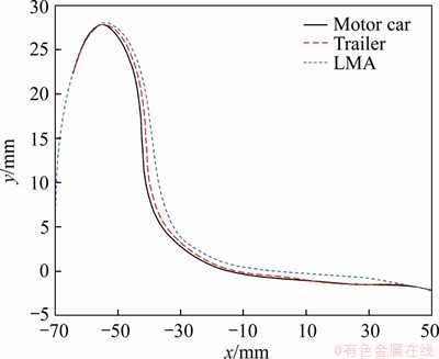
Figure 1 Worn wheel profiles
Two different wheel-rail three-dimensional rolling contact models were built by finite element method. A novel wheel wear rates calculation model was proposed in Archard wear model. These models could reveal the wheel-rail contact characteristics and calculate the wear rates of wheels in different cars separately.
2 Model
2.1 Dynamics model
The intercity train dynamics model composed of a motor car and a trailer was developed in the UM environment. Trailer was the first car of the train, and motor car was the second car as shown in Figure 2. There were a car body, two frames, four wheelsets and eight axle-boxes with total 86 degree of freedoms in each car model. The main difference between motor car and trailer was about the traction torque. Specifically, the traction torque M was applied on four motor car wheelset axles, but no traction torque was applied on trailer wheelset axles. The resistance Fr which was composed of air resistance and slope resistance determined by mass and speed of car was applied on each car body separately. For different structure of car body and the mass of motor and gear box, the mass of motor car was set to the value of 29.46 t which is larger than that of the trailer, i.e. 28.48 t, according to parameters of an intercity train in China.
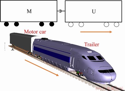
Figure 2 Train dynamics model
2.2 FEM model
The wheel-rail rolling contact models were built in the commercial finite element analysis software ABAQUS. There were two kinds of wheel-rail contact models, including wheel-rail three-dimensional steady-state rolling contact model and wheel-rail three-dimensional transient rolling contact model. The steady-state rolling contact model was built using Arbitrary Lagrangian Eulerian (ALE) formulation [26]. In static contact and steady-state rolling contact analysis, the freedom degree of x-axle was fixed in the wheel-rail three-dimensional steady-state rolling contact model. And transport velocity and motion velocity were applied to the wheel to simulate the rotation rates and forward velocity of wheel. The velocity field distribution in this model can be used as predefined field of wheel-rail three-dimensional transient rolling contact model to realize high-speed rolling of wheel. And the freedom degree of x-axle was released in the wheel-rail three-dimensional transient rolling contact model.
In two kinds of models, the fine mesh in size of 1 mm was used in the contact region of wheel and rail and larger mesh size was used in the regions without contact [27]. There were 275604 elements in total. The materials of wheel and rail were defined as the same, with the properties shown in Table 1. The friction coefficient was defined as 0.4. Fixed constrains were set at the bottoms of left and right rail. Normal load Fv, traction torque M and traction and longitudinal force Fl were applied at the center of motor wheel as shown in Figure 3(a). For the trailer wheel, no traction torque was applied as shown in Figure 3(b). Two methods were chosen to remove initial oscillations of the contact force in the wheel-rail three-dimensional transient rolling contact model. The first was setting the Rayleigh damping constant of wheel and rail material ��=1.0��10-5. The second method was connecting the wheel center to a vertical damping element with the damping coefficient of 4��106 N��s/m [28].
Coulomb friction model was chosen to define the wheel-rail tangential contact in ABAQUS. The wheel-rail tangential sliding was defined as finite sliding. Lagrange multipliers were used to enforce exact sticking condition and impose the constraint of non-tangential slip.
Table 1 Material properties of wheel and rail
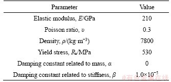
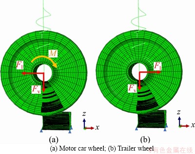
Figure 3 FEM model of wheel-rail contact:
In the stick region, the friction stress at contact nodes can be written as:
 (1)
(1)
In Eq. (1), qi is the integral of Lagrange multipliers; ����i is the differential of relative slip distance; ��i is the friction stress, i=1, 2, which implies longitudinal and lateral direction, respectively.
In the slip region, the friction stress can be written as:
 (2)
(2)
 (3)
(3)
 (4)
(4)
In Eqs. (1)-(4), k0 is a reference stick stiffness selected internal in ABAQUS; ����eq is the differential of composed relative slip distance; ��crit is the maximum value of friction stress; p is the contact pressure of node; ��eq is composite friction stress at the node; when ��eq>��crit, the contact statue of node would change into slip from stick.
2.3 Wear model
Archard studied the wear law between solid contact surfaces and proposed the corresponding wear model. In Archard wear model, the wear volume of contact body is function of the contact normal force and relative slip distance of contact body [29]. According to the Archard wear model, the wear rates of nodes can be expressed as follows:
 (5)
(5)
In Eq. (5), H is the hardness of materials of wheel, HV 260; vslip is the slip velocity; p is the normal contact pressure of node; w is the wear rate of node; k implies the wear coefficient. JENDEL [16] proposed the wear coefficient of wheel-rail contact based on the experiment [16]. The value of ki is shown in Figure 4. It is dependent on the slip velocity and contact pressure.
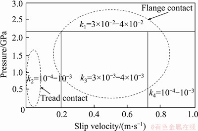
Figure 4 Chart of wear coefficient
A new calculation method of wear rate of the contact area on the wheel surface was proposed as shown in Figure 5. Firstly, the main dynamic indexes, including rotation rates and velocity of wheel, vertical force and longitudinal force acting on wheel from bogie and traction torque applied on wheel, were calculated in the vehicle dynamics simulation. Secondly, these factors were used as input parameters in the wheel-rail static contact analysis using the wheel-rail three-dimensional steady-state rolling contact model. The vertical force Fv was applied on the center of the wheel model. Thirdly, a transport velocity and motion velocity were applied on the wheel-rail steady-state rolling contact model. Stress and strain of wheel and rail would be calculated in this model to investigate the wheel-rail rolling contact characteristics at the constant speed. The rotation rates and velocity were both assigned on the wheel in this step. The velocity field distribution can be transported into the transient model as the predefined field. This step can decrease the transient rolling distance of wheel to realize the acceleration of wheel, and decrease computational cost. Fourthly, longitudinal force Fl and traction torque M were applied on wheels in the wheel-rail three-dimensional transient rolling contact model to investigate the wheel-rail contact characteristics under traction force. The wheel-rail contact pressure and relative slip velocity were derived in this model. Finally, the wear coefficient ki was determined according to the value of contact pressure, slip velocity and contact statue of nodes. The wheel wear rates were calculated by the procedure in Matlab according to Figure 5.
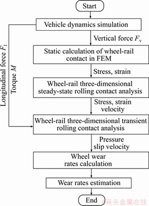
Figure 5 Wear rate calculation flowchart
3 Simulation result and discussion
3.1 Dynamics result
The speed of the intercity train in China usually is 200 km/h. The real traction characteristics and the resistance of the train in an operating intercity train were adopted, as shown in Figure 6. The traction force was set to the same value of resistance to keep the speed of intercity train at 200 km/h in straight track.
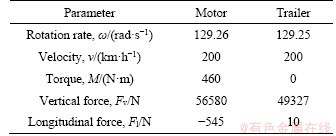
The rotation rate, velocity, which determined the wheel-rail creep characteristics, were calculated in straight track. The vertical force, longitudinal force acting on wheelset axle from bogie and the traction torque acting on the motor wheel are all shown in Table 2. The motor car wheel rotated a little faster than the trailer wheel. The motor car wheel encountered larger vertical force than trailer wheel because of the heavier car body. In addition, the longitudinal force acting on wheels showed big discrepancy, including the value and direction. The value of longitudinal force acting on motor car wheel was much bigger than that of trailer wheel. The longitudinal force acting on motor car wheel was negative, which implied that it was opposite to the forward direction.
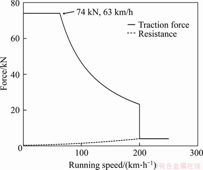
Figure 6 Traction characteristics curve [30]
Table 2 Main dynamic factor about wheel
3.2 Contact characteristics
The creep characteristics were investigated in wheel-rail three-dimensional transient rolling contact models for two kind of wheels. Figure 7 shows the longitudinal creep force and longitudinal creepage could reach steady state after the running distance of 0.1 m. The mean values of longitudinal creep force Fx in the steady state were 670 N and -315 N, which had different force directions. And the absolute value of creepage of the motor car wheel was twice as much as that of trailer as shown in Figure 7.
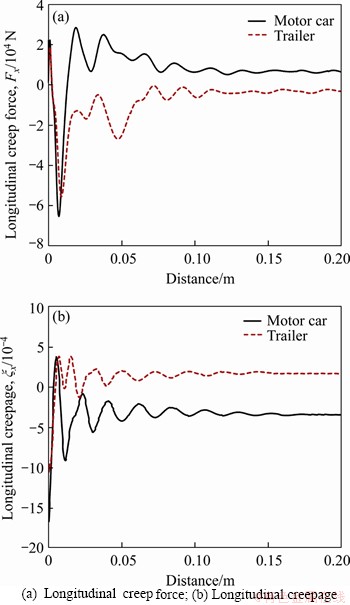
Figure 7 Creep characteristics:
Figure 8 shows the contact pressure of wheel in the contact patch. The maximum contact pressure of motor car wheel was 1120.4773 MPa, which was a little higher than that of trailer wheel,1038.2786 MPa. The areas of contact patch were 75 mm2 and 70 mm2 for motor car wheel and trailer wheel, respectively. The discrepancy was because of the larger vertical force acting on the motor car wheel.
The contact slip rates between wheel and rail are shown in Figures 9 and 10. The slip rate vector of two kinds of wheels both spun around the center of contact patch, and the spinning phenomenon in the motor car wheel was not as clear as that in the trailer wheel. Because the longitudinal creepage was lager, the maximum slip rate of the motor car wheel 44.3927 mm/s was larger than that of the trailer wheel 36.1856 mm/s. According to Eq. (5), because of the larger contact pressure and slip rates, the motor car encountered the higher wheel wear rates than that of trailer.
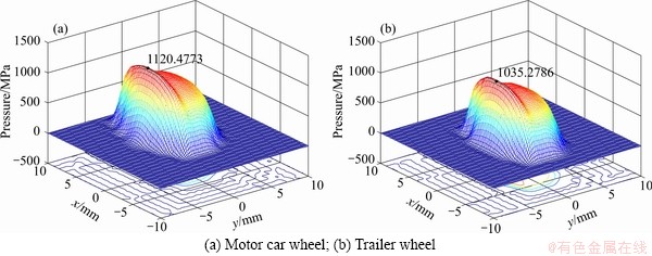
Figure 8 Contact pressure:
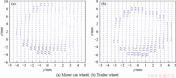
Figure 9 Slip rate vector diagram:
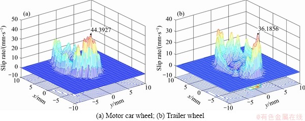
Figure 10 Slip rate of wheel:
3.3 Wear rate
The longitudinal creep force Fx can be divided into two part as shown in Eq. (6). Fx1 was caused by the wheel spin rolling for the contact angle between wheel and rail, and Fx2 was caused by traction force. Because the traction force had little influence to the lateral creep force Fy, the lateral creep force was mainly caused by wheel spin rolling. The contact patch was divided into stick region A1 and slip region A2 as shown in Figure 11. According to Eqs. (1) and (2), the creep force can be expressed as:
 (6)
(6)

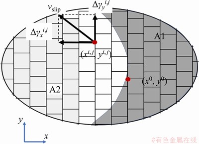
Figure 11 Contact patch diagram
 (7)
(7)

 (8)
(8)

 (9)
(9)
 (10)
(10)
 (11)
(11)
The wheel-rail relative slip rate can be expressed by the deviation of relative slip distance as shown in Eq. (12). The wear rates can be expressed by the relative slip distance in different directions as shown in Eq. (13):
 (12)
(12)

 (13)
(13)
In Eqs. (7)-(13), 
 are the longitudinal friction stress caused by the wheel spin rolling and traction force;
 is the lateral friction stress caused by the wheel spin rolling;
 are the differential of longitudinal slip distance caused by the wheel spin rolling and traction force;
  is the differential value of lateral slip distance caused by the wheel spin rolling; �� is the rotation rate; �� is the contact angle; xi,j, yi,j are the coordinates of node (i. j), respectively; x0, y0 are the coordinates of spinning center of contact patch, respectively.
Figure 12 shows the wear rates of two kinds of wheels. The distribution of wear rates was very similar to the distribution of slip rates. It indicated that the wear rates of wheel were influenced by the slip rates of wheel seriously. The maximum wear rate was distributed in the rear part of the contact patch, because the slip rates were largest in this part. The maximum wheel wear rates of motor car was 1.1665��10-6 mm/s which was about twice of that of trailer, 5.3118��10-7 mm/s. The three-dimensional maps of wear rates could only reflect the instantaneous wear rates of the wheel surface. To compare the wear rates of two kinds of wheels more clearly, the wear rates were accumulated to the wheel profile according to Eq. (14):
 (14)
(14)
In Eq. (14), wi, j is the wear rate of node (i, j); wi is the wear rate of wheel profile at node i.
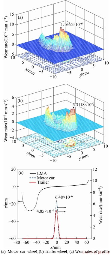
Figure 12 Wear rates of wheel:
The maximum wear rate of motor car wheel profile was 6.48��10-6 mm/km which was larger than that of trailer wheel profile, i.e. 4.85��10-6 mm/km, as shown in Figure 12(c). The wear rates three-dimensional distributions graphics of motor car wheel and trailer wheel were similar to each other. But wear rate values of motor car wheel were larger than that of trailer wheel, including the instantaneous wear rate of the wheel surface and wear rate of wheel profile.
3.4 Field test
The wear depths of two kinds of wheels in simulated results were compared with those in the field test results. The wheel wear depths of a Chinese intercity train, which was running from Dongguan to Huizhou at 200 km/h, were measured. The running mileage of the train was 800 km/d, and the wear depths of wheels were measured every 2��104 km each time. The wear depths of all the car wheels were measured with the wheel profile measurement designed by Tongji University, China, as shown in Figure 13(a). Mean values of the maximum wear depths of two kinds of car wheels were statistically analyzed during the mileage from 0 to 2.75��105 km. The field test results are shown in Figure 13(b). The maximum wear depths in simulation were the product of the maximum wear rates and the running mileage to contrast the simulation results and field test results.
In field test, at low mileage, the wear of wheel and rail profile was mild. Wheel and rail profile can match each other well. So, the effect of traction force on the wear of motor wheel was not obvious. As the mileage increased, the hollow wear of motor wheel was more serious than the wear of trailer wheel. The effect of traction force on the wear of motor wheel was more obvious than before. So, the discrepancy of motor wheel wear depth and trailer wheel wear depth was small when the running mileage was less than 1.0��105 km. But the wear speed of motor wheel became faster and this discrepancy became larger after the mileage reaching 1.0��105 km. In addition, the wear rates of motor car wheel and trailer wheel both increased with the increase of mileage.
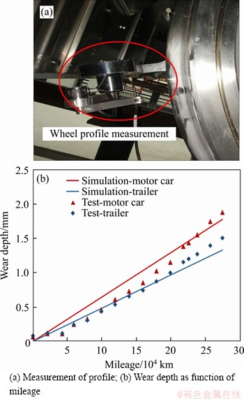
Figure 13 Contrast of wear rates and wear depths:
In simulation, the running speed was defined as 200 km/h, which was the highest allowed speed of the train. And the traction force used in the simulation would be larger than the average traction action on motor wheel in the actual operation at low mileage. So, the wear speed of wheel in simulation would be larger than that in test. There was relative large discrepancy between motor car wheel simulated wear depth and motor car wheel tested wear depth in Figure 13(b). Without the effect of traction force, the prediction of trailer wheel wear depth showed a good agreement with the tested result.
The wear speed was defined constant in simulation. The constant wear speed of wheels would be larger those at low mileage but smaller than those at high mileage for both motor and trailer wheel. However, the overall trends of wheel wear depth in simulated and tested results were similar. And they both showed the motor car wheel encountered the more serious wear than the trailer wheel.
4 Conclusions
To study the wheel wear depth discrepancy between motor car and trailer, the vehicle dynamics model of an intercity train and the wheel-rail three-dimensional rolling contact models were built. Based on the results from vehicle dynamics simulation and wheel-rail rolling contact simulation, the wear rates of motor car wheel and trailer wheel were calculated when the train was running in straight track at 200 km/h. The wheel wear depths of two kinds of cars in simulated and measured results were contrasted. Through the simulation and field test, the following conclusion can be obtained:
1) The motor car wheel rotated a little faster than the trailer wheel and encountered larger vertical force because of the heavier car body. In addition, the motor car wheel encountered larger longitudinal force from bogie.
2) Contrasted with trailer wheel, larger contact pressure and contact patch size distributed in the motor car wheel surface. The larger traction force caused by traction torque would result in the higher slip rates in the rear part of wheel contact patch and weaken the spinning phenomenon of relative slip in the motor car wheel.
3) Larger contact pressure and slip rates caused the higher wear rates of motor car wheel than those of trailer. The overall trends of wheel wear depth in simulated and tested results were similar. The simulated and measured results both showed the motor car wheel encountered the more serious wear than the trailer wheel.
4) For the different wear rates of wheels, the maintenance projects and re-profiling periods of motor car wheel and trailer should be arranged differently. These models can be used to study the effect of the traction characteristics curves on the wear of wheel.
Contributors
The overarching research goals were developed by ZHANG Ji-min. ZHANG Ji-min provided the research route. KOU Jie conducted the investigation and wrote the draft of manuscript. ZHOU He-chao reviewed and edited the draft of the manuscript. WANG Cheng-ping conducted the literature review. SUN Li-xia edited the draft of manuscript.
Conflict of interest
KOU Jie, ZHANG Ji-min, ZHOU He-chao, WANG Cheng-ping, SUN Li-xia declare that they have no conflict of interest.
References
[1] JIN Xue-song, XIAO Xin-biao, WEN Ze-feng, GUO Jun, ZHU Min-hao. An investigation into the effect of train curving on wear and contact stresses of wheel and rail [J]. Tribology International, 2009, 42(3): 475-490. DOI: 10.1016/j.triboint. 2008.08.004.
[2] BLANCO-LORENZO J, SANTAMARIA J, VADILLO E G, CORREA N. On the influence of conformity on wheel�Crail rolling contact mechanics [J]. Tribology International, 2016, 103: 647-667. DOI: 10.1016/j.triboint.2016.07.017.
[3] WANG Jian-xi, CHEN Xi, LI Xiang-guo, WU Yan-jie. Influence of heavy haul railway curve parameters on rail wear [J]. Engineering Failure Analysis, 2015, 57: 511-520. DOI: 10.1016/j.engfailanal.2015.08.021.
[4] LEWIS T D, JIANG J Z, NEILD S A, GONG C, IWNICKI S D. Using an inerter-based suspension to improve both passenger comfort and track wear in railway vehicles [J]. Vehicle System Dynamics, 2019, 58(3): 472-493. DOI: 10.1080/00423114.2019.1589535.
[5] MEYMAND S Z, KEYLIN A, AHMADIAN M. A survey of wheel-rail contact models for rail vehicles [J]. Vehicle System Dynamics, 2016, 54(3): 386-428. DOI: 10.1080/00423114. 2015.1137956.
[6] GU Shao-jie, YANG Xin-wen, ZHOU Shun-hua, LIAN Song-liang, ZHOU Yu. An innovative contact partition model for wheel/rail normal contact [J]. Wear, 2016, 366-367: 38-48. DOI: 10.1016/j.wear.2016.07.001.
[7] KALKER J J. On the rolling contact of two elastic bodies in presence of dry friction [D]. Netherlands: Delft University of Technology, 1967.
[8] KALKER J J. A fast algorithm for the simplified theory of rolling contact [J]. Vehicle System Dynamics, 1982, 11(1): 1-13. DOI: 10.1080/00423118208968684.
[9] LI Xia, JIN Xue-song, WEN Ze-feng, CUI Da-bin, ZHANG Wei-hua. A new integrated model to predict wheel profile evolution due to wear [J]. Wear, 2011, 271(1, 2): 227-237. DOI: 10.1016/j.wear.2010.10.043.
[10] WANG Pu, GAO Liang. Numerical simulation of wheel wear evolution for heavy haul railway [J]. Journal of Central South University, 2015, 22(1): 196-207. DOI: 10.1007/s11771-015-2510-1.
[11] VO K D, ZHU H T, TIEU A K, KOSASIH P B. FE method to predict damage formation on curved track for various worn status of wheel/rail profiles [J]. Wear, 2015, 322-323: 61-75. DOI: 10.1016/j.wear.2014.10.015.
[12] WANG Xue-ping, MA He, ZHANG Jun. A prediction method for wheel tread wear [J]. Industrial Lubrication and Tribology, 2019, 71(6): 819-825. DOI: 10.1108/ILT-10-2018-0397.
[13] TELLISKIVI T, OLOFSSON U. Contact mechanics analysis of measured wheel-rail profiles using the finite element method [J]. Proceedings of the Institution of Mechanical Engineers Part F-Journal of Rail and Rapid Transit, 2001, 215(2): 65-72. DOI: 10.1243/0954409011531404.
[14] DAMME S, NACKENHORST U, WETZEL A, ZASTRAU B W. On the numerical analysis of the wheel-rail system in rolling contact [C]// POPP K, SCHIEHLEN W. System Dynamics and Long-Term Behaviour of Railway Vehicles, Track and Subgrade. Lecture Notes in Applied Mechanics. Berlin, Heidelberg: Springer, 2003, 6: 155-174. DOI: 10.1007/978-3-540-45476-2_10.
[15] PEARCE T G, SHERRANTT N D. Predietion of wheel profile [J]. Wear, 1991, 144: 343-350. DOI: 10.1016/B978-0-444-88774-0.50027-4.
[16] ZOBORY, ISTVAN. Prediction of wheel/rail profile wear [J]. Vehicle System Dynamics, 1997, 28(2, 3): 221-259. DOI: 10.1080/00423119708969355.
[17] JENDEL T. Prediction of wheel profile wear��Comparisons with field measurements [J]. Wear, 2002, 253(1): 89-99. DOI: 10.1016/S0043-1648(02)00087-X.
[18] de ARIZON J, VERLINDEN O, DEHOMBREUX P. Prediction of wheel wear in urban railway transport: Comparison of existing models [J]. Vehicle System Dynamics, 2007, 45(9): 849-866. DOI: 10.1080/00423110601149335.
[19] JIN Xin-can. Evaluation and analysis approach of wheel-rail contact force measurements through a high-speed instrumented wheelset and related considerations [J]. Vehicle System Dynamics, 2020, 58(8): 1189-1211. DOI: 10.1080/00423114.2019.1612073.
[20] WANG Xue-ping, MA He, ZHANG Jun. A prediction method for wheel tread wear [J]. Industrial Lubrication and Tribology, 2019, 71(6): 819-825. DOI: 10.1108/ILT-10-2018-0397.
[21] SKRYPNYK R, EKH M, NIELSEN J C O, PALSSON B A. Prediction of plastic deformation and wear in railway crossings��Comparing the performance of two rail steel grades [J]. Wear, 2019, 428-429: 302-314. DOI: 10.1016/j.wear. 2019.03.019.
[22] LUO Ren, SHI Huai-long, TENG Wan-xiu, SONG Chun-yuan. Prediction of wheel profile wear and vehicle dynamics evolution considering stochastic parameters for high-speed train [J]. Wear, 2017, 392-393: 126-138. DOI: 10.1016/ j.wear.2017.09.019.
[23] SHEBANI A, IWNICKI S. Prediction of wheel and rail wear under different contact conditions using artificial neural networks [J]. Wear, 2018, 406-407: 173-184. DOI: 10.1016/j.wear.2018.01.007.
[24] HANDA K, MORIMOTO F. Influence of wheel/rail tangential traction force on thermal cracking of railway wheels [J]. Wear, 2012, 289: 112-118. DOI: 10.1016/ j.wear.2012.04.008.
[25] WANG Zhi-wei, WANG Rui-chen, CROSBEE D, ALLEN P, YE Yun-guang, ZHAN Wei-hua. Wheel wear analysis of motor and unpowered car of a high-speed train [J]. Wear, 2020, 444-445: 203136. DOI: 10.1016/j.wear.2019.203136.
[26] CHANG Chong-yi, WANG Cheng-guo, JIN Ying. Study on numerical method to predict wheel/rail profile evolution due to wear [J]. Wear, 2010, 269(3, 4): 167-173. DOI: 10.1016/j.wear.2009.12.031.
[27] ZHAO Xin, LI Zi-li. The solution of frictional wheel�Crail rolling contact with a 3D transient finite element model: Validation and error analysis [J]. Wear, 2011, 271(1, 2): 444-52. DOI: 10.1016/j.wear.2010.10.007.
[28] PLETZ M, DAVES W, OSSBERGER H. A wheel set/crossing model regarding impact, sliding and deformation��Explicit finite element approach [J]. Wear, 2012, 294-295: 446-456. DOI: 10.1016/j.wear.2012.07.033.
[29] ARCHARD J F. Contact and rubbing of flat surfaces [J]. Journal of Applied Physics, 1953, 24(8): 981-988. DOI: 10.1063/1.1721448.
[30] ZENG Yao-zheng, HUANG Wen-jie. On the traction system of CRH6 Intercity EMU [J]. Intercity Rail Transit, 2014, 3: 83-87. DOI: 10.16037/j.1007-869x.2014.03.021.
(Edited by ZHENG Yu-tong)
���ĵ���
�Ǽ��г��������ϳ��ij���ĥ�ĶԱ�
ժҪ��Ϊ�����Ǽ��г��������ϳ�����ĥ�IJ��죬�����һ���µij���ĥ�����ʼ���ģ�ͣ���ģ���ɳǼ��г�����ѧģ�͡��ֹ���ά�����Ӵ�����Ԫģ�ͺ�ĥ��ģ����ɡ��Ա��˷��������ֳ�ʵ�������������������������ֱ��ϳ����־��и����ת�ٺ������们�ʡ�ͬʱ�����ڳ�����غ�ǣ��ת�ص�Ӱ�죬���������ܵ�ת��ܸ���Ĵ��������������������ڶ��������ϵ�ǣ��ת�ؿ�����߳��ֽӴ��ߺ��们�ʣ������������们���ϴ�ĽӴ�ѹ���ͻ�����ʹ�������ֵ�ĥ���ʸ����ϳ����֡�������������������������ĥ����ȵ��������������Ƶģ��������ֱ��ϳ�����ĥ�ĸ�Ϊ���ء����������ģ�Ϳ������о�ǣ���������߶Գ���ĥ�ĵ�Ӱ�졣
�ؼ��ʣ�����ĥ�ģ��Ǽ��г����������ϳ�������Ԫ�������ֳ�����
Foundation item: Project(51805374) supported by the National Natural Science Foundation of China; Project(208YFB1201603-08) supported by the Key R&D Program of Ministry of Science and Technology, China
Received date: 2020-08-28; Accepted date: 2021-02-24
Corresponding author: ZHOU He-chao, PhD, Assistant Professor; Tel: +86-13701804471; E-mail: zhouhechao@tongji.edu.cn; ORCID: https://orcid.org/0000-0003-2722-922X
Abstract: To analyze wheel wear discrepancy between motor car and trailer of an intercity train, a novel wheel wear rates calculation model was proposed, which was composed of the intercity train dynamics model, wheel-rail three-dimensional rolling contact FEM model and the wear model. The simulated results were contrasted with measured results in field test. The simulated results showed the motor car wheels had larger rotation rate and longitudinal creepage than the trailer wheels. Meanwhile, the motor car wheels encountered larger vertical forces and longitudinal forces from bogie because of the heavier car body and the impact of traction torque. The traction torque acting on motor car wheel could increase the slip rates in the rear part of wheel contact patch and weaken the spinning phenomenon of relative slip. Larger contact pressure and slip rates caused the higher wear rates of motor car wheel than those of trailer wheel. The overall trends of wheel wear depth in simulated and tested results were similar. And they both showed the motor car wheel encountered the more serious wear than the trailer wheel. These models can be used to study the effect of the traction characteristics curves on the wear of wheel.
