

J. Cent. South Univ. (2020) 27: 3721-3732
DOI: https://doi.org/10.1007/s11771-020-4572-y

Mechanism of necking defect of 6082 aluminium alloy rolled by cross-wedge rolling method based on material thermal properties
WANG Dong-gang(������)1, 2, 3, SHU Xue-dao(��ѧ��)1, 3, WANG Rui(����)1, 3, XU Sheng(����)1, 2
1. Faculty of Mechanical Engineering & Mechanics, Ningbo University, Ningbo 315211, China;
2. Institute of Mechanical and Electrical Engineering, Zhejiang Business Technology Institute,Ningbo 315012, China;
3. Zhejiang Provincial Key Laboratory of Part Rolling Technology, Ningbo 315012, China
 Central South University Press and Springer-Verlag GmbH Germany, part of Springer Nature 2020
Abstract:
Necking defects have long troubled the application of cross-wedge rolling technology in aluminium alloy shaft parts. To accurately predict necking defects, new judgement conditions are established based on the thermal performance of 6082 aluminium alloy. The limit-sectional shrinkage without necking defects is achieved by combining theoretical calculation and finite-element model analysis, which couples heat transfer and deformation. In this paper, a 6082 aluminium alloy extruded rod with a 40 mm diameter rolled at a preheated temperature of 500 ��C and a rolling angular velocity of 1 rad/s is taken as an example. The simulation and experimental results show that necking defects do not occur on the rolled pieces if the sectional shrinkage is below the limit-sectional shrinkage but will occur when the sectional shrinkage is above it. The results prove that the prediction model of necking defects in cross-wedge rolling of 6082 aluminum alloy is feasible, and this research provides a theoretical basis for the qualified aluminum alloy shafts produced by the cross-wedge rolling.
Key words:
Cite this article as:
WANG Dong-gang, SHU Xue-dao, WANG Rui, XU Sheng. Mechanism of necking defect of 6082 aluminium alloy rolled by cross-wedge rolling method based on material thermal properties [J]. Journal of Central South University, 2020, 27(12): 3721-3732.
DOI:https://dx.doi.org/https://doi.org/10.1007/s11771-020-4572-y1 Introduction
With the development of new technologies and new processes, lightweight materials have become a new trend in the automotive industry [1], and aluminium alloy has become the first choice for its high specific strength and high formability. The 6082 aluminium alloy in the Al-Mg-Si series of aluminium alloys has become the most commonly used aluminium alloy in the automotive industry due to its excellent overall performance, high specific strength and good processability. However, the forming performance of 6082 aluminium alloy is greatly affected by the temperature, the strain rate and the degree of deformation [2]. The deformation resistance of 6082 aluminium alloy decreases when the temperature rises, and the tensile resistance decreases too. Therefore, the high temperature performance must be studied in the forming process. The flow stress behaviour of 6082 aluminium alloy under the deformation temperature of 300-500 ��C and the strain rate of 0.01-10 s-1 is studied and the dynamic recovery is found to be the typical softening mechanism when a transition from strain hardening toward steady deformation [3].
Although 6082 aluminium alloy has many advantages, its application in the automotive industry is greatly restricted due to low material utilization. The cross-wedge rolling (CWR) process is often used to make billets to improve the material utilization by redistributing the material [4]. CWR is a forming process for reshaping a round stock into a rotationally symmetrical workpiece with variable diameter in axial direction with two oppositely moving wedge-shaped dies [5]. The mechanical structure of round CWR process is shown in Figure 1. The forming process of the billet is mainly determined by the wedge tools, and the guide plates are used to prevent the workpiece from swinging during deformation.
The divisions of the forming zones, the forming surfaces and the parameters of the dies are shown in flat CWR dies for convenience in Figure 2 [5]. The CWR dies are usually divided into three zones according to the forming stage and its characteristics [6]: (a) the knifing zone, (b) the stretching zone and (c) the sizing zone, as shown in Figure 2. In the knifing zone, wedges are cut into the blank; in the stretching zone, the material deformation begins to expand in the axial direction; and in the sizing zone, shaft bending and surface defects are corrected [7].
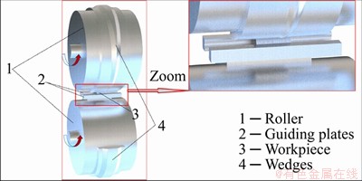
Figure 1 Mechanical structure of round cross wedge rolling process
Despite its advantages, many process defects occur because of the complicated deformation mechanism. Necking defects are among the most common problems of aluminium alloy due to the axial component force during the CWR process [8]. As shown in Figure 3(b), when a necking defect occurs, the product becomes thinner locally, and the mechanical performance of the productg drops sharply.
Many scholars have studied the necking mechanism. TSUKAMOTO and HAYAMA established the judgment conditions of limit- sectional shrinkage (LSS), in which the effect of parameters such as the forming angle ��, the spreading angle �� and sectional shrinkage �� is more comprehensively analyzed on the necking defects [9-11]. JIA et al [12, 13] performed an in-depth study of the necking mechanism of heavy section shrinkage in the CWR process and proposed the relationship between the spreading angle �� and the LSS. PATER et al [14] proposed a necking mechanism according to the first strength theory, which confirmed that necking would occur during the CWR process if the tensile stress (caused by the axial component) is greater than the yield stress of the material, and he recommended the new equations related to the forming angle, the spreading angle, the sectional shrinkage and other processing parameters to determine the limit condition for the CWR process. JIA et al [15] presented the distribution coefficient of area reduction to analyse the laws of necking in twice-stage.
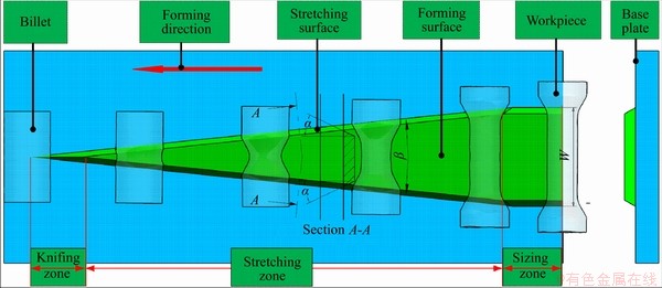
Figure 2 Typical CWR die and its division

Figure 3 Normal workpiece (a) and necking workpiece (b)
The judgement conditions above have explained the relationship among the die parameters, the sectional shrinkage and the necking mechanism clearly and have been applied in the analysis of many necking defects in the CWR process successfully. However, to improve plasticity, to reduce deformation resistance and to reduce process defects, the billet is often preheated in the CWR process [16]. And the forming performance of the heat-sensitive materials changes greatly with temperature, so the necking mechanism is much more complicated [17]. The 6082 aluminium alloy is a heat-sensitive material, so its tensile strength drops sharply at high temperatures, and its flow stress also changes greatly with the temperature and the strain rate. Therefore, the influence of the deformation temperature and the deformation rate on the properties of the material must be considered to predict necking defects accurately. In early studies, technical restrictions made it impossible to reasonably predict the distribution of the internal temperature field, which restricted further study of the necking mechanism. The development of computer technology has greatly facilitated the prediction of the distribution of the internal temperature field [18].
In this paper, the 6082 aluminium alloy rod extruded with the preheated temperature of 500 ��C and the rolling speed of 1 rad/s is taken. The distribution law of the temperature field in the deformation zone is obtained by theoretical calculation and numerical simulation, and the functional relationships among the limit radius rlim, the geometric parameter G and the material parameter M is obtained to determine the LSS. This theory thus has great significance for accurate prediction of the LSS and improvement in the quality of aluminium alloy products of CWR.
2 Thermal mechanical performance of 6082 aluminium alloy
In the CWR process, the material��s thermal performance is the most important factor for the forming quality. Because the 6082 aluminium alloy is a heat-sensitive material, its flow stress and strength limit will change significantly at high temperatures.
2.1 Calculation of strength limit ��b of dangerous section
The strength limit of the 6082 aluminium alloy drops sharply as the temperature increases above 200 ��C, and the relationship between the strength limit and the temperature of the 6082 aluminium alloy is approximately logarithmic and can be expressed by Formula (1) according to the experimental data [19].
 (1)
(1)
where T is the temperature of the material in ��, and ��b is the strength limit of 6082 aluminium alloy at temperature T. The strength limit ��b is calculated according to Formula (1).
2.2 Calculation of flow stress ��f in deformation zone
Rolling stock with sectional shrinkage of 57.8% (d2=26 mm) was selected to calculate the LSS. To calculate the flow stress ��f, the Z-parameter [20] must first be obtained, as shown in Formula (1). The average strain rate  in the forming process is obtained from Formulas (2) and (3) [21], and Z is calculated with instead of the strain rate
 for simplification.
 (2)
(2)
 (3)
(3)
 (4)
(4)
T in Formula (2) is the absolute temperature of the deformation area of 6082 aluminium alloy, d0 is the diameter of the billet (40 mm), ��d is the maximum reduction and R is the radius of the top surface of the dies. Finally, Z is substituted into Formula (4) to obtain the flow stress ��f.
 (5)
(5)
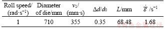
All parameters are shown in Table 1.
Table 1 Simulation scheme with different sectional shrinkages
2.3 Relationship curves of ��b and ��f with temperature
According to the Formulas (1), (2), (3), (4) and (5), the changes of ��b and ��f with temperature are shown in Figure 4; ��b and ��f can be obtained if the temperature distribution is known.

Figure 4 Relationship between flow stress ��b and strength limit ��f of 6082 aluminium allowy and temperature
3 Establishment of finite-element model
The billet drawing and the artifact drawing are shown in Figures 5(a) and (b), respectively. Because different sectional shrinkage must be used during the simulation and the experiment, the diameters in the sizing zone are expressed by the variable d.
The dies are important guarantee for product forming. As shown in Figure 6, the forming angle takes the value 30�� to avoid internal hole defects, and the spreading angle takes a larger value between 4�� to 9�� to reduce the length of the dies [9], where Rb is the radius of the base circle of the dies and R is the top radius of the dies.
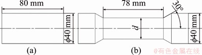
Figure 5 Billet drawing (a) and artifact drawing (b)
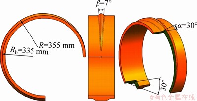
Figure 6 Design parameters of dies
To reduce the amount of calculation without affecting the accuracy of the simulation results in this project, the pre-processing of FEM is set as follows:
1) The process temperature has a great influence on the deformation process, so the FEM coupling deformation and heat transfer are established.
2) The billet is assumed to be isotropic, and Mises yield criterion is selected as the yield criterion.
3) Due to the large plastic deformation and even rheology of the deformed body during the CWR process, the elastic deformation can be ignored, so the deformed body adopts a rigid plastic FEM.
4) Little deformation occurs on the dies and the guides, so they are set as rigid bodies.
5) Shear friction is selected as the type of friction between the dies and the rolled piece.
All parameters related to the finite-element simulation are shown in Table 2.
The geometric model of the finite-element model (FEM) in the CWR process is shown in Figure 7.
4 Analysis of numerical simulation results
The simulation scheme is shown in Table 3.
Table 2 Parameter setting of CWR simulation parameter
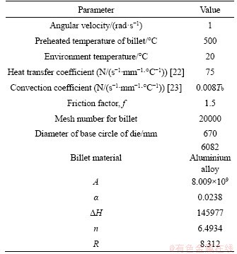
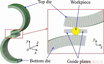
Figure 7 FEM of CWR
Table 3 Simulation scheme with different sectional shrinkage
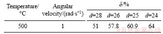
The sectional shrinkage of rolled pieces are selected between 50% and 70% by taking the integer value of final forming diameters between 24 and 28 mm.
4.1 Analysis of mechanism of necking defect
The heat exchange during hot CWR is a complicated physical process that includes heat conduction between the deformed body and the dies, the convective heat exchange between the deformed body and the air mixed with the heat radiation and the effect of deformation work. Because the 6082 aluminium alloy is a heat-sensitive material, the accuracy of numerical calculation of macro- mechanical indicators such as the strain and the stress can be greatly improved by considering the influence of temperature on the entire deformation [25].
Figure 8 shows a cross-sectional view of the rolling process, and the upper half of the deformation zone of the rolled piece is studied. Point K is the tangent point of the top fillet of the die and the sizing zone. A perpendicular line is drawn from K to the axle of the rolled piece, and the intersect point is drawn as A. The intersection point between the AK and the surface of the rolled product is B. The highest contact point of the die and the surface of the rolled piece is point C, so ��ABC is defined as the deformation zone during the CWR process.

Figure 8 Schematic of temperature distribution in deformation zone
As shown in Figure 8, four points are taken on lines BC and AB in the same distance, respectively, and P1 is selected as the common point. The average temperature on the line BC is the effective temperature T1, which is selected as the temperature to calculate the flow stress ��f, and the average temperature on line AB is the effective temperature T2, which is selected as the temperature to calculate the strength limit ��b. The temperature at point Pi is presented as Tpi. The effective temperature is shown as Formula (5).
 (6a)
(6a)
 (6b)
(6b)
It is assumed that a necking defect occurs if the effective stress on the cross-section AB of the rolled product exceeds the material��s strength limit ��b. The limit radius rlim without necking defects can be expressed as Formula (7).
 (7)
(7)
 (8)
(8)
 (9)
(9)

 (10)
(10)
where Saxial is the projected area of the deformed area in the axial direction, r0 is the radius of the billet, C is the distance between the centre of the die and the billet, R is the top radius of the dies and  is the flow stress, with strain rate
 and temperature T1 in the deformation zone.
  is the strength limit with the sectional temperature of T2.
In the end, the LSS ��lim can be expressed as Formula (11).
 (11)
(11)
Therefore, the limit condition for the CWR process relates not only to the geometric parameter G, but also to the material��s thermal performance parameter M. The larger the value of M, the smaller the limit section shrinkage. This can allow a more accurate judgment of the necking defect condition.
To calculate the LSS accurately, points tracked are taken in three positions in the stretching zone, including the initial stage, the middle stage and the end stage respectively. The temperature distribution lines are drawn in the deformation zone in Figures 9(a), (b) and (c), and four floating points on the lines AB and BC are selected for tracking in the deformation zone.
The changes in the temperatures of the tracked points are shown in Figure 10. It can be seen from the figure that the temperature begins to decline linearly, and obviously fluctuates from the adjacent stretching zone until entering the sizing zone, and begin to decreases steadily.
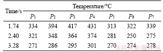
As shown in Table 4, the temperatures of different points with the maximum difference at the time of 1.74 s, 2.40 s and 3.28 s are obtained from the simulation data, respectively.
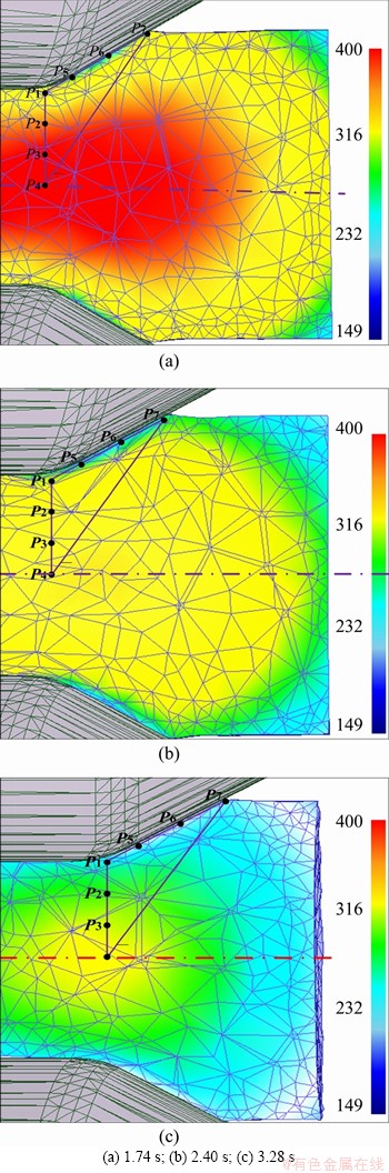
Figure 9 Tracked points in stretching zone at different times:
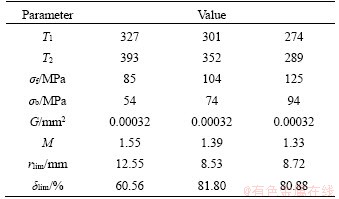
T1 and T2 can be obtained according to Formula (6a), (6b) and Table 4, so ��b and ��f can be obtained according to Figure 4. All geometric parameters are substituted into Formula (9) to obtain G. The LSS ��lim can be obtained according to Formula (11). The calculated results are shown in Table 5.
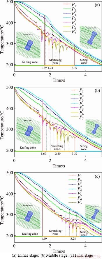
Figure 10 Changes in temperature of tracked points in stretching zone in different stages:
Table 4 Temperatures of points at maximum temperature difference in different positions
It is shown in Table 5 that the geometric parameter G of the rolled piece is a fixed value when the die parameters and the section shrinkage are determined, at various stages of the stretching section of CWR. However, the material parameter M differs completely in various stages because the effective temperatures on lines AB and BC of the rolled piece changes. According to Formula 9, the thermal properties of the 6082 aluminium alloy material, including its strength limit and flow stress, differ significantly, which affect the limit sectional shrinkage of the rolled part at various stages. The theoretical calculations above show that the most likely necking position is the initial stage of the stretching section at 1.74 s, as shown in Figure 9(a). It can be concluded that a necking defect will occur on the rolled piece when the LSS is greater than 60.56%.
Table 5 Calculated results
4.2 Prediction of shrinkage defects
4.2.1 Damage analysis of tracked points
The necking defects of rolling products relate to the generation and propagation of internal micro- cracks. The damage model developed by Cockcroft- Latham is mainly used in the Deform software, which is shown in Formula (12) [26].
 (12)
(12)
where D is the critical value for the macro-crack of the material, which indicates the degree of damage; ��1 is the first principal stress;  is the effective stress;
  is the effective plastic strain; and
  is the effective strain in the current state.
To compare the degree of damage to different rolled pieces at different positions in the Deform 3D software, two longitudinal feature points and two radial feature points were taken in the longitudinal section of every rolled piece with different sectional shrinkage. Figure 11 shows the location of these tracked points. The cross section A-A is the symmetry plane of the rolled piece, and the B-B plane is the cross section of the forming end position, and the distance from the B-B plane to section plane A-A is 38 mm. P1, P5, P9 and P13 are the points of the axis of the deformed body on the A-A surface; P2, P6, P10 and P14 are the points of the axis of the deformed body on the B-B plane; P3, P7, P11 and P15 are the points 1 mm below the forming surface on the A-A plane; and P4, P8, P12 and P16 are the points 1 mm below the forming surface on the B-B plane.
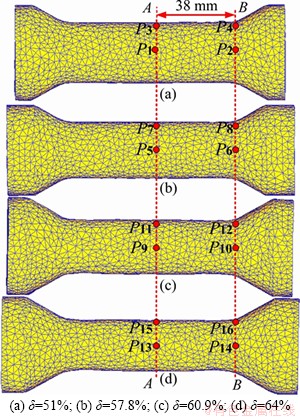
Figure 11 Damage factor with different shrinkage:
Figure 12 shows a comparison of the damage factor at the same location of the rolled pieces with different sectional shrinkage. Because the damage factor is the result of an accumulation of damage, it gradually increases as the process proceeds. The damage degree of a point is closely related to the sectional shrinkage of the rolled piece. At the same position, the higher the sectional shrinkage is, the greater the damage factor and the greater the possibility of damage at that point.
4.2.2 Analysis of internal fields
Figure 13 shows the differences in the damage factor, displacement field and temperature field in the rolled pieces with different sectional shrinkage.
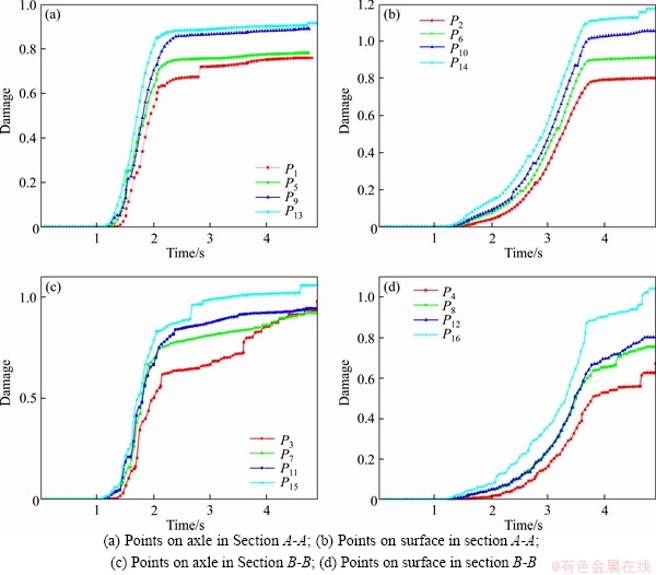
Figure 12 Position of tracked points with different sectional shrinkage:
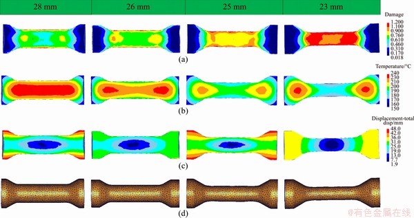
Figure 13 Comparison of damage factor (a), temperature field (b), internal displacement field (c) and FEM of rolled piece with different sectional shrinkage (d)
As is shown in Figure 13(a), the largest internal damage factor is less than 0.9 when the diameter is less than 26 mm. As the sectional shrinkage increases, the damage factor gradually increases. When the sectional shrinkage reaches 60.94%, which exceeds the calculated LSS of 60.56%, most of the stretching zone of the rolled part reaches 0.9 and even reaches 1.1 in some sections. When the sectional shrinkage reaches 66.94%, most of the damage factor of the stretching zone of the rolled part reaches 1.2, which indicates that the rolled product has been seriously damaged. As is shown in Figure 13(b), the temperature field distribution shows that the low-temperature metal on the surface and the high-temperature metal inside gradually form ��convection�� as the sectional shrinkage increases. When d=25 mm, the temperature distribution of the surface metal is discontinuous, which indicates that the inner and outer metals have combined. Thereby, surface defects are formed.
The displacement field describes the metal movement process. Figure 13(c) shows that when the sectional shrinkage is small, the metal flows in layers. As the cross-sectional shrinkage rate increases, the axial continuity of the metal displacement on the surface of the metal gradually breaks. When d=26 mm, the metal displacement field just happens to be damaged along the axial direction, which indicates that the metal of the rolled product has been separated on the surface, and when d=23 mm, the metal displacement field is obviously damaged along the axial direction and begins to become perpendicular to the axis. The discontinuity of the displacement in the axle indicates that the material has been separated, so the rolled part has experienced a severe surface spiral mark.
5 Experimental verification
The experimental scheme is shown in Table 6.
Table 6 Experimental scheme

It is shown in Table 5 that the LSS is 60.56%. To verify the accuracy of the calculation results, rolled pieces with different sectional shrinkage were rolled in the experiment. As shown in Figure 14, little change happened in the minimum cross- sectional diameter when d��26 mm. However, obvious necking defect occurs when the sectional shrinkage reaches 60.94%, and serious necking defects occur when the sectional shrinkage reaches 66.94%.
Figure 15 shows the parameters related to the necking defects. The assessment of the necking degree mainly includes parameters such as the final diameter, the necking diameter, the necking width and Dd. As the sectional shrinkage increases, the decrease in the necking diameter and the increase in the necking width gradually accelerate. As shown in Figure 16, the necking degree shows obvious acceleration when the sectional shrinkage exceeds the calculated LSS of 60.56%, which fully proves the accuracy of the calculated results.

Figure 14 Final deforming diameter and size of necking diameter

Figure 15 Diagram of necking product
6 Conclusions
The geometric parameter G and the material parameter M are considered in the new judgement condition of the necking defect of the CWR process based on the thermal performance of 6082 aluminium alloy. It can thus be used more widely with higher accuracy.
As the sectional shrinkage increases, surface quality defects will occur for the ��convection�� of the surface and internal metal in the WCR process of the 6082 aluminium alloy, which makes the surface temperature distribution uneven. The internal and external damage coefficient increases with the increasing of the sectional shrinkage, which indicates that the damage is more likely to occur.
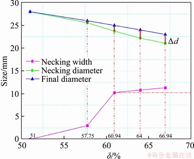
Figure 16 Analysis of necking degree with different sectional shrinkage
The simulation and experimental results show that necking defects will occur when the sectional shrinkage exceeds 60.56%, that is, the calculated LSS, and necking defects will accelerate with the increases of the sectional shrinkage.
Nomenclature
��b
The strength limit
��f
The flow stress
The strain rate

The average strain rate
��d
Cross wedge rolling reduction of diameter of billet
R
The radius of base circle of dies
v1
Linear speed of top surface of dies of rolling
d0
Diameter of the billet
Z
Z parameter of material
M
Material related parameter
G
Geometry related parameter
TPi
The temperature at point Pi
f
Coefficient of friction between dies and billet
��
The forming angle
��
The spreading angle
Saxial
The projected area of the deformed area in the axial direction
C
The distance between the centre of the die and the billet
��lim
The limit section shrinkage
Contributors
WANG Dong-gang makes the experimental plans, performs data processing, performs finite element simulations, and writes the paper. SHU Xue-dao determines the direction of the paper and the purpose of the experiment. WANG Rui assists to complete the experiment and helps to revise the paper. XU Sheng assists to complete the experiment and checks the literature.
Conflict of interest
WANG Dong-gang, SHU Xue-dao, WANG Rui and XU Sheng declare that they have no conflict of interest.
References
[1] WANG Tao. Key manufacturing technology and application status of aluminum alloy automotive body parts [J]. Automobile Applied Technology, 2020, 7: 187-189, 202. DOI: 10.16638/j.cnki.1671-7988.2020.07.055. (in Chinese)
[2] ZHANG Ping, SONG Ai-li, FANG Yu-xin, YUE Xiu-jie, WANG You-qiang, YU Xiao. A study on the dynamic mechanical behavior and microtexture of 6082 aluminum alloy under different direction [J]. Vacuum, 2020, 173: 109119. DOI: 10.1016/j.vacuum.2019.109119.
[3] RYOU H, ROMBERG E, PASHLEY D H, TAY F R, AROLA D. Importance of age on the dynamic mechanical behavior of intertubular and peritubular dentin [J]. J Mech Behav Biomed Mater, 2015, 42: 229�C242. DOI: 10.1016/j.jmbbm.2014.11.021.
[4] DENG Yu-ping, ZHAO Ning-ning, ZHAO Xiao-lian. Finite element simulation of cross wedge rolling aluminium alloy shaft parts [J]. Hot Working Technology, 2016, 45(3): 128-131,135. DOI: 10.14158/j.cnki.1001-3814. 2016.03. 036.
[5] BEHRENS B A. Cross wedge rolling [M]// The International Academy for Production. CHATTI S, LAPERRIERE L, REINHART G, TOLIO T. CIRP Encyclopedia of Production Engineering. Springer, Berlin, Heidelberg, 2018. https://doi.org/10.1007/978-3-642-35950-7_16804-2.
[6] JIA Zhi, ZHOU Jie, JI Jin-jin, YU Ying-yan, XIAO Chuan. Influence of tool parameters on internal voids in cross wedge rolling of aluminum alloy parts [J]. Transactions of Nonferrous Metals Society of China, 2012, 22(S1): 21-26. DOI: 10.1016/ S1003-6326(12)61678-1.
[7] LIU Yi-an, LIU Hua-min, WU Wei, WU Xiang-nan, WANG Hu. Simulation research of die forging process of 6082 aluminum alloy control arm [J]. Journal of North China Institute of Aerospace Engineering, 2016, 26(4): 11-13. DOI: 10.3969/ j.issn.1673-7938.2016.04.004. (in Chinese)
[8] CAI Ya-ning, ZHANG Kang-sheng, LOU Yi-zhi, HU Zheng- huan. Effect of forming angle on central defect of twice cross wedge rolling [J]. Forging & Stamping Technology, 2008, 33(3): 68-71. DOI: 10.3969/j.issn.1000-3940.2008.03.019.
[9] ZHOU Jie, YU Ying-yan, ZENG Qiang. Analysis and experimental studies of internal voids in multi-wedge cross wedge rolling stepped shaft [J]. International Journal of Advanced Manufacturing Technology, 2014, 72: 1559-1566. DOI: 10.1007/s00170-014-5768-9.
[10] KACHE H, NICKEL R, BEHRENS B A. An innovative cross wedge rolling preforming operation for warm forging [M]// Enabling Manufacturing Competitiveness and Economic Sustainability.Berlin, Heidelberg:SpringerBerlin Heidelberg, 2011: 310-315.
[11] PATER Z, GONTARZ A, WERONSKI W. Cross-wedge rolling by means of one flat wedge and two shaped rolls [J]. Journal of Materials Processing Technology, 2006, 177(1-3): 550-554. DOI: 10.1016/j.jmatprotec.2006.03.232.
[12] JIA Zhen, ZHANG Kang-sheng, YANG Cui-ping, HU Zheng-huan. Forming principle of heavy section shrinkage cross wedge rolling by single wedge [J]. Journal of University of Science and Technology Beijing, 2009, 31(8): 1046-1050. DOI: 10.13374/j.issn1001-053x.2009.08.013. (in Chinese)
[13] JIA Zhen, ZHANG Kang-sheng, TANG Xian-gang, HU Zheng-huan. Analysis on principle of spread width��s effect on cross wedge rolling limit-section shrinkage [J]. Transactions of Beijing Institute of Technology, 2010: 30(6): 655-659. DOI: 10.15918/j .tbi t1001 -0645.2010.06.007. (in Chinese)
[14] PATER Z, WERONSKI W, KAZANECKI J, GONTARZ A. Study of the process stability of cross wedge rolling [J]. Journal of Materials Processing Technology, 1999, 92-93: 458-462. DOI: 10.1016/s0924-0136(99)00229-0.
[15] JIA Zhi, ZHOU Jie, JI Jin-jin, LEI Zhen-zhen, XIANG Dong, SUN Xiao-tian. Influence analysis of area reduction for necking in twice-stage cross wedge rolling [J]. Int J Adv Manuf Technol, 2013, 66: 1407-1413. DOI: 10.1007/ s00170-012-4418-3.
[16] XU Huang, WANG Bao-yu, ZHOU Jing, JI Hong-chao, MU Yan-hong, LI Jun-ling. Comparative study of warm and hot cross-wedge rolling: Numerical simulation and experimental trial [J]. International Journal of Advanced Manufacturing Technology, 2017, 92(9-12): 3541-3551. DOI: 10.1007/ s00170-017-0399-6.
[17] LI Ju-qiang. Hot forge ability parameter identification and grain refinement study of wrought magnesium alloys [D]. Shanghai: Shanghai Jiao Tong University. 2015. (in Chinese)
[18] SHU Xue-dao, LIU De-yi, SHEN Guang-xian. Analyzing rolling pressure of rolling strip by multi-object contact multi-pole boundary element method [J]. Advanced Materials Research, 2012, 428: 14-18. DOI: 10.4028/www. scientific.net/AMR.428.14.
[19] SUN Xiao-hong, YANG Meng, KONG De-meng, HE Jian-ying, LI Xiao-ming. Research on mechanical property of 6082-T6 aluminum alloy at low and elevated temperature [J]. Electric Welding Machine, 2019, 49(2): 51-54. DOI: 10.7512/j.issn.1001-2303.2019.02.10. (in Chinese)
[20] SHI H, MCLAREN A J, SELLARS C M. Constitutive equations for high temperature flow stress of aluminum alloys [J]. Materials Science & Technology, 1997, 13(3): 210-216. DOI:10.1179/026708397790302421.
[21] ZHAO D W, TIE W L. A precise method of calculating the parameter: The mean strain rate in rolling [J]. Journal of Applied Sciences. 1995, 13(1): 103-108. DOI: CNKI:SUN: YYKX.0.1995-01-015. (in Chinese)
[22] GAO Feng-shan, XI An-min, LIU Hong-fei, WANG Chao. Analysis of temperature field of hot rolled work roller of aluminum sheet [J]. Journal of Northeastern University (Natural Science). 2015, 36(10): 1496-1500. DOI: 10.3969/ j.issn.1005-3026.2015.10.028. (in Chinese)
[23] AN Meng-meng, YANG Hong-hai, WU Ya-hong, ZHANG Wei-feng, DING Zhen-fang. Theoretical and experimental study on the characteristics of air plate-fin radiator [J]. Building Energy & Environment. 2018, 37(1): 27-31. DOI: CNKI:SUN: JZRK.0.2018-01-006. (in Chinese)
[24] WEI W. Research on hot deformation behavior and microstructure property of 6082 aluminum alloy forging with rib [D]. Beijing: Beijing Institute of Mechatronics, 2013. (in Chinese)
[25] SHU X D, SUN B S, PENG W F. Cross wedge rolling theory and forming technology [M]. Beijing: Science Press, 2014. (in Chinese)
[26] SILVA M L N, PIRES G H, BUTTON S T. Damage evolution during cross wedge rolling of steel DIN 38MnSiVS5 [J]. Procedia Engineering 2011, 10: 752-757. DOI: 10.1016/j.proeng.2011.04.125.
(Edited by HE Yun-bin)
���ĵ���
���ڲ��������ܵ�Ш��������6082���Ͻ���ľ�������
ժҪ�����Ͻ����������Ш���������еľ���ȱ�ݳ��������Ÿü�����ʵ�������е�Ӧ�á�ΪȷԤ�⾱��ȱ�ݷ���ʱ�ļ����������ʣ��������µĻ���6082���Ͻ������ܵľ���ȱ���ж�ģ�ͣ���ͨ�����ۼ�������-����ϵ�����Ԫģ�����ϵķ�ʽ��ʵ�ּ����������ʵ�Ԥ�⡣������ֱ��Ϊ40 mm��6082���Ͻ�ѹ��Ϊ����ģ��չ���Ǻͳ��νDz��䣬��Ԥ���¶�Ϊ500 ��C���������ٶ�Ϊ1 rad/s�������£��Բ�ͬ�����������µ�Ш�����ķ����������������˷����������ʵ�������������������ʵ��ڼ�����������ʱ�����Ͻ������û�г�������ȱ�ݣ����������ʸ��ڼ�����������ʱ�����������Ͻ�������ȱ�ݡ��ý��֤����6082���Ͻ�Ш��������ȱ�ݵ�Ԥ��ģ���ǿ��е�,���о�ΪШ�������ƺϸ�����Ͻ�����ṩ���������ݡ�
�ؼ��ʣ�6082���Ͻ�Ш�����������������ʣ������������¶ȳ�
Foundation item: Project(51975301) supported by the National Natural Science Foundation of China; Project(LZ17E050001) supported by the National Natural Science Foundation of Zhejiang Province of China
Received date: 2020-05-13; Accepted date: 2020-10-01
Corresponding author: SHU Xue-dao, PhD, Professor; E-mail: shuxuedao@nbu.edu.cn; ORCID: https://orcid.org/0000-0001-9928-7344
Abstract: Necking defects have long troubled the application of cross-wedge rolling technology in aluminium alloy shaft parts. To accurately predict necking defects, new judgement conditions are established based on the thermal performance of 6082 aluminium alloy. The limit-sectional shrinkage without necking defects is achieved by combining theoretical calculation and finite-element model analysis, which couples heat transfer and deformation. In this paper, a 6082 aluminium alloy extruded rod with a 40 mm diameter rolled at a preheated temperature of 500 ��C and a rolling angular velocity of 1 rad/s is taken as an example. The simulation and experimental results show that necking defects do not occur on the rolled pieces if the sectional shrinkage is below the limit-sectional shrinkage but will occur when the sectional shrinkage is above it. The results prove that the prediction model of necking defects in cross-wedge rolling of 6082 aluminum alloy is feasible, and this research provides a theoretical basis for the qualified aluminum alloy shafts produced by the cross-wedge rolling.
