

Structural characteristics and formation mechanisms of
crack-free multilayer TaC/SiC coatings on carbon-carbon composites
LI Guo-dong(�����)1, 2, XIONG Xiang(�� ��)1, HUANG Bai-yun(�Ʋ���)1, HUANG Ke-long(�ƿ���)2
1. State Key Laboratory of Powder Metallurgy, Central South University, Changsha 410083, China;
2. School of Chemistry and Chemical Engineering, Central South University, Changsha 410083, China
Received 1 June 2007; accepted 24 August 2007
Abstract:
In order to improve high temperature (over 2 273 K) ablation resistance, TaC and TaC/SiC composite coatings were deposited on carbon-carbon composites by CVD method utilizing reactive TaCl5-C3H6-H2-Ar and TaCl5-C3H6-CH3SiCl3-H2-Ar systems respectively. The structure and morphology of these coatings were analyzed by XRD and SEM. The results show that the double carbide coatings have good chemical compatibility during preparation. Two distinctive composition gradients are developed and used to produce multilayer TaC/SiC coatings with low internal stress, free crack and good resistant to thermal shock. A transition layer consisting of either C-TaC or C-SiC formed between the coating and the C/C matrix can reduce the residual stress effectively. The processing parameters were optimized and the possible growth mechanisms for these coatings were proposed. A designing methodology to prepare high performance multilayer TaC/SiC composite coatings was developed.
Key words:
carbon-carbon composite; TaC; SiC; structure; formation mechanism;
1 Introduction
With low density, high specific strength and retention of mechanical properties at elevated temperatures, carbon/carbon(C/C) composites offer many advantages over traditional structural materials. They have become candidate materials for hyperthermal ablation and were found wide applications in aerospace and aviation industry. However, C/C composites are prone to oxidation and can be washed out by high speed gas at high temperature[1-5]. These have then limited their applications for high performance aerospace vehicles.
Extensive work has been carried out and put on oxidation protection of C/C composites in last two decades[2-8]. External coating is an effective method to improve oxidation resistance of continuous carbon fiber strengthened C/C composites. For example, SiC, Si3N4, SiO2, borate glass and SiC-MoSi2 systems have exhibited good anti-oxidation ability below 2 023 K[9-10]. However, due to the increasing rate of oxidation, these materials cannot be used as anti-oxidation coatings alone in practice for prolonged service life.
STRIFE and SHEEHAN[5] have proposed a combined model for oxidation resistant coating over 2 073 K, where the constituent components of coating from outside to inside consist of oxide/SiO2 glass/ oxide/carbide. Some of the oxides could be HfO2, ZrO2, Y2O3 and ThO2 etc, while the carbides may include TaC, HfC, ZrC, TiC, SiC, etc. The outer layer of high hardness is functioned as the resistance to washout and hot erosion. The middle layer is used to prevent oxygen permeation. The bottom layer of low thermal expansion coefficient is designed such that it can produce strong bond with carbon matrix. However, due to its relative poor resistance to thermal shock, it is difficult to make ideal oxidation resistant coating. This is especially true when the thermal expansion coefficient of the carbide at the bottom layer happened to be larger than that of the C/C composites. At this moment, cracks can easily occur during the preparation, which affects the resistance to oxidation and causes the ablation of the coating. Accordingly, the preparation of crack-free carbide coatings compatible with the mechanical properties of C/C matrix is the key for the materials of good ablation resistance at ultrahigh temperature.
Besides high melting point (4 153-4 273 K), TaC has high hardness, good resistance to washout and erosion, and stable chemical property. TaC coating exhibits high strength in particular at high temperature and shows good chemical compatibility with the C/C composites. It does not have phase transformation below melting point. When being heated in oxidizing atmosphere over 2 260 K, a molten tantalum-oxide protective film will form on its surface to retard further oxidation of TaC. Therefore, TaC has been considered as a good candidate material of good ablation resistance for C/C composites at ultrahigh temperature. Unfortunately, in addition to poor resistance to thermal shock, the thermal expansion coefficient of TaC is too large compared with that of C/C composites (roughly by more than four times). On the other hand, of smaller expansion coefficient, SiC has high hardness, good resistance to washout and erosion, and good chemical stability. Its compatibility with C/C composites is fairly good too. In addition, its oxide (SiC+2O2=SiO2+CO2) shows excellent antioxidant performance below 2 023 K. It is therefore interesting to think about the strategy to combine TaC with SiC to make composition gradient composite coatings through some available means like chemical vapor deposition(CVD).
The objective of this work is then to investigate the design methodology, preparation and structural morphology of coatings of TaC (as reference) and TaC/SiC composite. The formation mechanism and optimal preparation conditions of crack-free TaC/SiC composite coatings were discussed.
2 Experimental
Utilizing the TaCl5-C3H6-H2-Ar and the CH3SiCl3- H2-Ar systems, TaC and SiC coatings can be produced on C/C surface by CVD method according to the following reactions:
TaCl5+1/3C3H6+3/2H2��TaC+5HCl (1)
CH3SiCl3+H2��SiC+3HCl+H2 (2)
where H2 is functioned as either the reactant in reaction (1) or catalyzer in reaction (2).
The scheme of CVD system is shown in Fig.1. The deposition was carried out in a graphite furnace. The furnace temperature was monitored by a photoelectric thermometer and controlled automatically. The gas flux was measured by flow meter. The flux of the reacting gas C3H6 and H2 is adjustable by a gas flux control system. The TaCl5 powders were fed by a special apparatus under the deposition furnace. The feeding system consists of powder bin, helical deliver pipe, agitator and motor. Adjusting the helix rotation speed of deliver pipe and the loading gas flux, we can control the flux of the TaCl5 powders. CH3SiCl3 (MTS) was heated to designed temperature by a constant temperature heater and carried by Ar. The transition of deposition or co-deposition can be adjusted by valve 1 and valve 2.
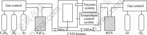
Fig.1 Scheme of CVD-TaC/SiC coating deposition system
The deposition temperature was chosen between 1 273 and 1 573 K, where both TaC and SiC coatings can be produced very well. The furnace pressure was controlled between 0.2 and 0.5 MPa. Other important parameters including the flux and ratio of TaCl5, CH3SiCl3, H2, C3H6 and Ar are listed in Table 1.
Table 1 Parameters of CVD-TaC/SiC coatings

The experimental matrix was C/C composites with a density of 1.8 g/cm3. The carbon fiber prefab was quasi-3D integral felt with matrix mainly consisting of CVI pyrolytic carbon. The sample (d 80 mm��50 mm) was first polished using 200 grit, then 600 grit waterproof abrasive papers, and cleaned with ultrasonic washer for 30 min, dried at 383 K for 2 h, and weighed.
The phase compositions and surface residual stress of the coatings were measured by D/max2550VB+18kW X-ray diffractometer with rotating target, and the morphologies of the coatings were observed by scanning electron microscope and optic microscope.
3 Results and discussion
3.1 Phase compositions of TaC-SiC compound ceramic
Little work on TaC-SiC compound ceramic has been reported in open literature. It has not been confirmed whether the intermediate compound between TaC and SiC could ever be produced, just as for the cases that TaC may react with either ZrC or HfC to form the intermediate compounds of ZrC?4TaC and HfC?4TaC due to the lack of relevant thermodynamic data[11].
We started with pure Ta, Si and C powders and they are mixed according to TaC to SiC mole ratio of 1?1. The mixture was compressed and heated in vacuum furnace at 2 473 K for 4 h. The XRD pattern of the product is shown in Fig.2. All samples display TaC, SiC and C peaks, but no other diffractive peaks are found. The appearance of low-intensity C peaks is attributed to the volatilization of Si during heat treatment. Moreover, there is no indication of any new phase formation even we vary the TaC to SiC ratio. This result indicates that there is no intermediate compound or solid-solution formed between TaC and SiC even during chemical vapor co-deposition of TaC and SiC. And consequently the two carbides should have good chemical compatibility at high temperature.

Fig.2 XRD pattern of products prepared from Ta, Si, C at 2 473 K
3.2 Characteristics of TaC coating
The surface morphology of a single TaC coating is generally canliflower-like[12-14], similar to that of SiC. As the thermal expansion coefficient of TaC ((6.7-8.2)�� 10-6 K-1) is more than 4 times larger than that of the C/C matrix, large elongated surface cracks often appear easily (see Fig.3(a)). Of heterogeneous nucleation nature, a thin and dense TaC layer of columnar crystals is deposited on the surface of C/C matrix. Crack-free transition structure of acicular crystals then form on top of the thin TaC layer. When the coating is thick enough, interlaminar cracks appear between the dense layer and the transition layer (Fig.3(b)) due to large internal stress.

Fig.3 Surface (a) and cross-sectional (b) SEM images of single TaC coating
Utilizing high speed CVD at low temperature, lots of nanosized pores are formed in the transition layer. Consequently, hardness, elastic modulus, linear expansibility and thermal stress of the TaC coating are decreased. So the thermal shock resistance of TaC coating is effectively improved[12-13].
3.3 Characteristics of multilayer TaC/SiC composite coatings
Due to good chemical compatibility with adjustable thermal expansion, TaC/SiC composite has exhibited novel layered structure with morphology differing significantly from both TaC and SiC single coating. The multilayer TaC/SiC composite coating consists of alternative interlayer of TaC and SiC with typical morphology shown in Fig.4. The crystal structure is still acicular or columnar and there is no obvious composition change between the layers. Besides the surface cracks are observed on apparent interface together with interlaminae between the TaC and SiC layers. This is due to the difference in chemical composition and the lattice parameters and thermal expansion mismatch as well. With SiC layer appeared on the top of the surface, there are break-ups or local bubbles presented on thick or thin coating (Figs.4(a) and (b)) due to the formation of tensile stress exerted by underneath TaC layer.

Fig.4 Surface morphologies (a, b) and cross-sectional SEM images (c, d) of TaC/SiC coatings (Arrows 1 and 2 show cracking tendency at interface of TaC and SiC. Region 1 shows surface cracks of coatings dispersed to many smaller and interlaminar ones instead of transfixion cracks)
Despite the fact that stress concentration is still presented at the interface between the layer of TaC and SiC, it is possible to get rid of cracks of the coating within suitable thickness range. Internal stress leading to the crack formation at natural fracture section can be seen from interfaces 1 and 2 in Fig.4(c). Once TaC layer appears on the surface, it is easy to get exfoliated, but the crack will not transfix in general. The interlaminar stress or cracks appeared in TaC/SiC composite coating with interlaminar composition gradients have been diversified to the transfixion cracks perpendicular to the surface. As can be seen in Fig.4(d), the big cracks in region 1 are divided or dispersed into many small and interlaminar ones in the third and fourth sub-layers. As the result of such a diversity or dispersion, both the break-up and rapid oxidation along the depth of transfixion cracks can be avoided or mitigated.
Note that the interface now becomes new growth surface for the next layer of coating. The interface not only provides heterogeneous nucleation sites for next layer, but also permits the transition region for lattice adjustment with such defects as amorphous phase and pores leading to the variation of thermal expansion. So the growth stress and thermal stress can be significantly released and absorbed.
3.4 Characteristics of multilayer TaC/SiC composite coatings with double gradients
As shown in Fig.5(a), the composite coating contains double composition gradients, i.e., local component gradient and integral component-wave-center gradient. In other words, the coating can be considered composed of sub-coatings with unique component waves. Locally at each sub-coating, the TaC component varies with continuous gradient change either from high to low or from low to high concentration, while the SiC component change is exactly in opposite direction. There is a co-deposition region of TaC-SiC with component variation existing in the interlamination with no apparent boundary observable between these two layers. The components of TaC or SiC alternate from low to high value and move backwards, which results in the component fluctuation similar to sine or cosine waves. The average component TaC of neighboring sub-coatings varies from low to high value moving towards coating surface from matrix, while that of SiC changes from high to low. Since average values change gradually, we called them component-wave-center gradients.

Fig.5 Cross-section SEM images of multilayer TaC/SiC composite coatings with double gradients
Since the existence of local component gradient (the first gradient) causes thermal expansion mismatch, it can therefore significantly reduce the thermal stress and decrease the tendency of crack formation, especially those interlaminar cracks. Consequently, the local component gradient can release the thermal stress of the coating. However, the thermal expansion coefficient of TaC/SiC composite coating is still higher than that of C/C composite. As a result, it is easy to form cracks perpendicular to coating surface.
As seen from Fig.5(b), transfixion cracks with poor resistance to thermal shock can be observed. Accordingly, general component gradient can decrease cracks, but not eliminate cracks.
The multilayer TaC/SiC composite coatings with double gradients are characterized by fluctuation of component and stress distribution. The otherwise concentrated stress is dispersed from one stress concentration zone to entire surface of the coating. In addition, the local tensile stress is counteracted by contiguous compression stress. When the SiC content of the outer layer is higher than that of the inner ones (i.e., in the second gradient), it will exert compression stress on the surface during cooling. The tensile stress caused by the higher expansion coefficient of TaC/SiC coating can be counteracted further. As a result, the big radial transfixion cracks and interlaminar ones, as shown in Fig.4(d), can be avoided.
The results of residual stresses of coating surfaces measured by X-ray diffractometer are listed in Table 2. From Table 2 we can see that, without composition gradient, multilayer TaC/SiC composite coating has larger tensile stress. While for double gradients, the coating surface has smaller compression stress and can effectively reduce the cracks and enhance the resistance to thermal shock, oxidation and ablation.
Table 2 Results of residual stress of coating surfaces (MPa)

3.5 Function of C-TaC and C-SiC transition coatings
With sufficient carbon, it is possible to have co-deposition of C-TaC or C-SiC. As the free carbon is deposited inside, this will lead to the inner structure change of the coating. The bonding strength between the coating and the matrix will increase and the thermal expansion coefficient of coatings will decrease. It��s effective to deposit C-TaC or C-SiC gradient transition coatings on the C/C matrix surface in order to reduce thermal stress and eliminate abnormal crack formations. As shown in Fig.5(a), a 2-5 ?m thick transition layer of C-TaC between the C/C matrix and TaC/SiC coating can avoid the interlaminar cracks parallel to the matrix surface (see Fig.3(b)). Either C-TaC or C-SiC can be deposited onto the gradient coating with component fluctuation. The reason that the fluctuating gradient composite coating is better than the general gradient coating has been explained in Ref.[13].
According to Table 2, with C-TaC, the surface tension of TaC coating is decreased effectively. Cracks are reduced remarkably once we use C-TaC as the transition layer between TaC coating and C/C matrix. With suitable adjustment, we can eliminate the cracks. This is attributed to the addition of free carbon by lowering the strain shrinkage during cooling. The reason is the thermal expansion coefficient of C-TaC is smaller than that of TaC coating. The structure of C-TaC is similar to that of TaC coating and they have good compatibility and strong combination. Moreover, the elastic modulus is decreased significantly. With proper control of gradient and thickness, the contractive cracking of inner TaC can be eliminated.
According to the law of additivity for composites, the elastic modulus Ec and linear thermal expansion coefficient ��c of the coating can be determined by the combination shape fraction (Ei, ��i) and volume fraction ��i of the raw materials[15]:
![]() (3)
(3)
![]() (4)
(4)
where -1��n��1 is determined by experiments. Since the elastic modulus and thermal expansion coefficient of CVD-C are much smaller than those of CVD-TaC, we are expected to see those values dropping for C-TaC coating based on Eqns.(3) and (4).
With temperature difference ?T, the maximum stress �� of the coating can be expressed as
��=Ec��c(Tm-T)/(1-��c) (5)
where Tm is the average temperature and ��c is Poisson ratio of the coating with smaller changes. Thus, if the temperature difference is the same, the maximum stress of C-TaC will be much smaller than that of TaC coating. With increasing the carbon content, the thermal stress of the C-TaC coating will reduce and its thermal shock resistance will increase. So, it is reliable to use the C-TaC gradient as transitional layer between matrix and the TaC coating.
Similarly, the interface stress and cracks can be effectively reduced by using the co-deposition layer of TaC-SiC as the gradient transition layer for TaC and SiC coatings.
3.6 Preparation of crack-free TaC/SiC composite coatings with low residual stress
An excellent TaC/SiC composite coating should meet the requirements for real working conditions with excellent resistance to high temperature washout, oxidation, ablation, and good compatibilities with the matrix. On one hand, the coating should have good chemical compatibility with the matrix without generating any new phase or leading to inhomogeneous aggregation. One good example is metal carbide which has the best chemical compatibility with C/C composites. On the other hand, the coating should have good mechanical compatibility with the matrix during preparation and in service. Thermal stress, growth stress, structural stress and corresponding strain from both coating interior and the interface between the coating and the matrix shall cause damage to the coating or matrix. No crack is permitted in order to meet such requirements. It is also required that the coating should have perfect resistance to thermal shock (for example, thermal gradient above 2 273 K/s during rocket ignition) with low residual stress (tensile stress) at room temperature (crack-free) and low compression stress as high temperature (no breaking from matrix). The brittleness and thermal expansion mismatch are the shortcoming of carbides and their compression strength is far beyond their tensile strength, which should be paid enough attention in choosing suitable deposition temperature, pressure and flow rate during the preparation. The conditions of crack-free TaC/SiC composite coatings with low residual stress are as follows.
Firstly, the uniformity of C/C matrix, especially the thermal expansion of C/C matrix parallel to coating orientation, is the key for high quality coatings. The difference of thermal expansion existing among carbon fiber in axial (Fig.5(a)) and radial direction (Fig.5(b)), and that between the carbon fiber and CVD-C can cause thermal expansion non-uniformity along different directions and on surface positions parallel to the fiber felt. Meanwhile, the C/C composite prepared by different carbon fiber felts can lead to the difference of thermal expansion uniformity in different directions.
Secondly, the gradient transition layer of C-TaC or C-SiC can enhance the bonding strength of the coating and matrix effectively and then reduce the interface stress and erase the cracks.
Thirdly, in the TaC/SiC composite coating, certain gradient has been formed between the TaC and SiC coating. The thickness of TaC or SiC layer should be less than 5-10 ?m, but the thickness of co-deposition of TaC-SiC coating can beyond 20 ?m. Apparently, double gradients coatings are better than single gradient coating.
Fourthly, the coating surface is composed of SiC or C-TaC, C-SiC, etc. Coatings with small expansion coefficients are beneficial to the formation of micro-compression-stress layers on the surface, which can help to eliminate the transfixion cracks.
Fig.6 shows a typical design of crack-free thick multilayer TaC/SiC composite coatings with low stress. The homogenous and dense C/C composites are chosen as the matrix material. The depositing layers are in turn CVD-C, C-TaC, SiC, TaC, SiC, TaC, ???, TaC-SiC, SiC-TaC, TaC-SiC, ???, TaC, SiC, ???, TaC and SiC. Each of these sub-layers has little thickness and gradient area with minimum component fluctuation. The surface stress is measured to be -3.35 MPa (see Table 2). The thermal shock experiment was carried out at 2 573 K with oxyacetylene flame and laser ablation[14]. The result shows no break-up and apparent abscission. This implies that the coating has good thermal shock resistance.

Fig.6 Cross-sectional SEM images of crack-free TaC/SiC composite coatings with low stress
4 Conclusions
1) Based on TaCl5-C3H6-H2-Ar and CH3SiCl3-H2-Ar reactive systems, the crack-free thick multilayer TaC/SiC composite coatings with low stress can be successfully produced on C/C surface by chemical vapor deposition.
2) Multilayer TaC/SiC composite coatings without composition gradient tend to cause stress concentration at interfaces and interlaminar cracks among layers. While those with double gradients can reduce stress concentration at interface, generate micro compression stress on the surface, which helps to eliminate transfixion cracks.
3) By taking C-TaC and C-SiC as transition layers between the matrix and coating, the stress concentration can be released. The bonding strength between the matrix and coating can be enhanced and the crack occurrence can be reduced.
Acknowledgments
The authors thank Professor ZOU Zhi-qiang of State Key Laboratory of Powder Metallurgy for important advice and suggestions in this study, also the authors thank Mr. ZHOU Zhong-lian of Powder Metallurgy institute for his helps in improving experimental conditions.
References
[1] BACOS M P, DORVAUX J M, LAVIGNE O, RENOLLET Y. C/C composite oxidation model (I): Morphological experimental investigations [J]. Carbon, 2000, 38(1): 77-92.
[2] BACOS M P, COCHON J L, DORVAUX J M, LAVIGNE O. C/C composites oxidation model (��): Oxidation experimental investigations [J]. Carbon, 2000, 38(1): 93-103.
[3] SCHMIDT D L, DAVIDSON K E, THEIBERT L S. Unique applications of carbon-carbon composites materials (Part one) [J]. SAMPE, 1999, 35(3): 27-39.
[4] WESTWOOD M E, WEBSTER J D, DAY R J, HAYES F H, TAYLOR R. Oxidation protection for carbon fiber composites [J]. J Mater Sci, 1996, 31: 1389-1397.
[5] STRIFE J R, SHEEHAN J E. Ceramic coatings for carbon-carbon composites [J]. Ceram Bull, 1988, 67(2): 369-374.
[6] LEE Y J, JOO H J. Ablation characteristics of carbon fiber reinforced carbon (CFRC) composites in the presence of silicon carbide (SiC) coating [J]. Surf Coat Tech, 2004, 180/181: 286-289.
[7] LAUB B. Thermochemical ablation of tantalum carbide loaded carbon-carbons [C]// AIAA 15th Thermophysics Conf. New York: AIAA-80-1476, 1980.
[8] HUANG H M, WANG J X, WU L Z, DU S Y. Ablation of carbon-carbon composite during re-entry [J]. J Harbin Tech Inst, 2000, 7(4): 16-20.
[9] VAUGHN W L, MAAHS H G. Active-to-passive transition in the oxidation of silicon carbide and silicon nitride in air [J]. J Am Ceram Soc, 1990, 73(6): 1540-1543
[10] MCCAULEY R A. Corrosion of ceramics [M]. New York: Marcel Dekker, 1995: 98-149.
[11] ANDRIEVSKII R A,STREL''NIKOVA N S, POLTORATSKII N I,KHARKHARDIN E D,SMIRNOV V S. Melting point in systems ZrC-HfC, TaC-ZrC, TaC-HfC [J]. Powder Metallurgy and Metal Ceramics, 1967, 6(1): 65-67.
[12] LI G D, XIONG X, HUANG B Y. Microstructure characteristic and formation mechanism of crackfree TaC coating on C/C composite [J]. Trans Nonferrous Met Soc China, 2005, 15(6): 1206-1213.
[13] LI G D, XIONG X, HUANG B Y. The influences of CVD temperature on composition, surface morphology and microstructure of TaC coatings [J]. The Chinese Journal of Nonferrous Metals, 2005, 15(4): 565-571. (in Chinese)
[14] LI G D, XIONG X. Study on ablation character of TaC coating by low power laser [J]. J Mater Sci Eng Powder Metall, 2005, 10(3): 155-159. (in Chinese)
[15] BOLEY B A, WEINER J H. Theory of thermal stress [M]. New York: Wiley, 1985: 202-290.
Foundation item: Project(2007AA03Z110) supported by the National Hi-tech Research and Development Program of China; Project(2006CB600908) supported by the National Basic Research Program of China; Project(20070420822) supported by the China Postdoctoral Science Foundation; Project(2007RS4027) supported by the Postdoctoral Science Foundation of Hunan Province, China; and Project supported by the Postdoctoral Science Foundation of Central South University, China
Corresponding author: LI Guo-dong; Tel: +86-731-8830899; E-mail: lgd63@163.com
