

Developing friction stir welding window for AA2219 aluminium alloy
A. K. LAKSHMINARAYANAN, S. MALARVIZHI, V. BALASUBRAMANIAN
Centre for Materials Joining & Research (CEMAJOR), Department of Manufacturing Engineering,
Annamalai University, Annamalai Nagar-608 002, Tamil Nadu, India
Received 27 January 2011; accepted 6 April 2011
Abstract:
A friction stir welding window was developed for effective joining of AA2219 aluminium alloy. Joints were fabricated using different combination of process parameters such as rotational speed and welding speed. Based on macrostructural analysis, the friction stir welding window was constructed. The strength values of joints at different regions of friction stir welding window were analyzed using tensile properties, microstructural studies, and the fracture location of joints was correlated with the lowest hardness distribution profiles. These windows will act as reference maps for selecting appropriate friction stir welding process parameters to get good quality welds of AA2219 aluminium alloys.
Key words:
friction stir welding window; aluminium alloy; lowest hardness distribution profile; tensile strength;
1 Introduction
Friction stir welding (FSW) is a revolutionary, environment friendly solid-state welding technology invented in 1991 by The Welding Institute (TWI), and ever since this method has gathered widespread interest in a variety of applications in automotive, aerospace and construction industries. Presently, the FSW studies have been mainly focused on the Al alloy plate, which has great demand in various industries over conventional welding process. The FSW process is at present entering into the initial stage of commercialization and the research has mainly been concentrated on the area of process development, including tool design and process control [1]. There is also a growing interest in numerical modeling of friction stir welding process, since in the FSW process the welding parameters are all chosen such that the softening of the workpiece material enables the mechanical deformation and material flow. However, unlike many other thermomechanical processes, the mechanisms of FSW are fully coupled, i.e., the heat generation is related to material flow and frictional/ contact conditions and vice versa [2].
Though numerical modelling of plastic flow can aid tool design and optimisation of weld quality, there is no application of models towards the prediction of practical processing maps or friction stir welding window (FSWW). From the previous studies [3-4], it is well understood that, the effect of some important parameters such as rotational speed and welding speed on weld properties is the major topics for researchers. In all the above cases, the FSW parameters are selected by trial and error to fix the working range to get defect free welds. This conventional approach is time consuming and calls for enormous resources. Hence, it is necessary to construct the friction stir welding window so that it will be useful to predict the optimum range of friction stir welding process parameters. The joints were fabricated under different processing conditions and the friction stir welding window was constructed based on macrostructural analysis. To further improve the joint efficiency of friction stir welded AA2219 aluminium joints, the optimum processing region within the FSWW was identified by analyzing the joints fabricated at different locations of friction stir welding window through tensile properties, lowest hardness distribution profile and microstructural studies.
2 Experimental
The rolled AA2219-T87 aluminium alloy plates of 8 mm in thickness were cut into the required size (300 mm��150 mm) by power hacksaw cutting and milling. Square butt joint configuration was prepared to fabricate FSW joints. The initial joint configuration was obtained by securing the plates in position using mechanical clamps. The direction of welding was normal to the rolling direction. Single pass welding procedure was followed to fabricate the joints. Non-consumable tools made of high carbon steel were used to fabricate the joints. The chemical composition and mechanical properties of the base metal are presented in Tables 1 and 2, respectively. An indigenously designed and developed machine (11 kW, 3 000 r/min, 25 kN) was used to fabricate the joints using different combination of rotational speed and welding speed. The welding process parameters, their levels and tool dimensions are shown in Table 3. The welded joints were sliced using power hacksaw and then machined into the required dimensions to prepare tensile specimens as shown in Fig. 1. American Society for Testing of Materials (ASTM-E8M-04) guidelines were followed for preparing the test specimens. Tensile tests were carried out in 100 kN, electro-mechanically controlled universal testing machine (Make: FIE-Bluestar, India; Model: UNITEK-94100). The specimen was loaded at the rate of 1.5 kN/min as per ASTM specifications, so that the tensile specimen underwent deformation. The specimen finally failed after necking and the load versus displacement was recorded. The 0.2% offset yield strength, ultimate tensile strength and percentage of elongation were evaluated. The Vicker��s microhardness testing machine (Make: Shimadzu, Japan; Model: HMV-2T)) was employed for measuring the hardness across the joint with 4.9 N load.
Table 1 Chemical composition of base metal (mass fraction, %)
![]()
Table 2 Mechanical properties of base metal

Table 3 Process parameters and levels
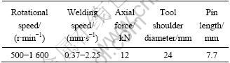

Fig. 1 Dimension of tensile specimen (unit: mm)
Macro and microstructural analyses were carried out using a light optical microscope (Make: MEJI, Japan; Model: MIL-7100) incorporated with an image analyzing software (metal vision). The specimens for metallographic examination were sectioned to the required sizes from the welded joints and polished using different grades of emery papers. Final polishing was done using the diamond compound (1 ��m particle size) in the disc polishing machine. Specimens were etched with Kellers reagent to reveal the macro and microstructures.
3 Developing friction stir welding window
In fusion welding of aluminium alloys, the defects like porosity, slag inclusion, solidification cracks, etc deteriorate the weld quality and joint properties. Usually, the friction stir welded joints are free from these defects since there is no melting taking place during welding and the metals are joined in the solid state due to the heat generated by the friction and flow of metal by the stirring action. However, FSW joints are prone to other defects like pinhole, tunnel defect, piping defect, kissing bond, cracks, etc due to improper flow of metal and insufficient consolidation of metal in the FSP region [5]. The flow-related defects occur outside the acceptable processing window with parameters that are considered either too hot or too cold. Under hot processing with stick conditions, excessive material flow results in flash formation, surface galling and nugget collapse. Under cold processing with slip conditions, insufficient flowing of material results in surface lack of fill, wormhole, or lack of consolidation defects on the advancing side. It is speculated that the optimum processing conditions to prevent flow related defects occur at a temperature where stick�Cslip wiping flow occurs and material flowing from the region ahead of the pin tool is exactly balanced with that flowing back into the vacated region behind the tool [6]. In this investigation, macrostructure analysis (defect free or defective joints) was used to find out the optimum processing condition by analyzing the joints fabricated using different combination of rotational speed and welding speed.
3.1 Macrostructural analysis
A large number of experimental runs were carried out using 8 mm-thick rolled plates of AA2219-T87 aluminium alloy to find out the feasible working limits of FSW process parameters. Different combinations of process parameters were used to carry out the trial runs. This was carried out by varying one of the factors while keeping the rest of them at constant values. All the joints fabricated in this investigation were analysed at low magnification (10��) using optical microscope to reveal the quality of FSP regions. The working range of each process parameter was decided upon by inspecting the macrostructure (cross section of weld) for a smooth appearance without any visible defects such as tunnel defect, pinhole, lazy S, etc. The rotational speed of 700 to 1 600 r/min yielded defect free joints depending on the welding speed used, and the welding speed in the range of 30 to 150 mm/min yielded defect free joints depending on the rotational speed used. At an average downward force of 12 kN, the rotational speed and welding speed were varied within the above mentioned processing range to find the defective and defect free joint of friction stir welded AA2219 joints. The macrostructures of the joints fabricated using welding speeds of 30-150 mm/min and rotational speeds of 500-1 300 r/min used to construct the FSWW are presented in Tables 4-8.
3.2 Constructing friction stir welding window
From the macrostructural analysis, the defective or defect free joints were identified and they were plotted in a two dimensional graph with the rotational speed in Y-axis and the welding speed in X-axis as shown in Fig. 2. The selection of friction stir welding process parameters inside the window region always yielded defect free friction stir welded joints of AA2129 aluminium alloys, and this was validated by conducting few more experiments. To understand the effect of welding condition (i.e. heat input) on the quality of joints, lower hardness distribution profile, microstructural analysis and tensile properties of three different regions within friction stir welding window (FSWW) were examined. The details of microstructural analysis, tensile behavior and lowest hardness distribution profile will be discussed in the following sections.
Table 4 Macrostructures of AA2219 aluminium alloy joints fabricated with welding speed of 30 mm/min

Table 5 Macrostructures of AA2219 aluminium alloy joints fabricated with welding speed of 60 mm/min
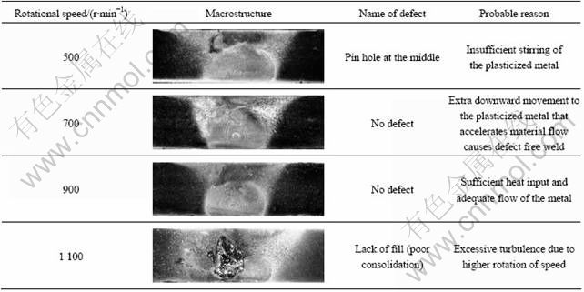
Table 6 Macrostructures of AA2219 aluminium alloy joint fabricated with welding speed of 90 mm/min
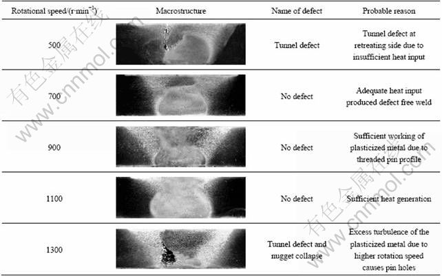
Table 7 Macrostructures of AA2219 aluminium alloy joint fabricated with welding speed of 120 mm/min

Table 8 Macrostructures of AA2219 aluminium alloy joint fabricated with welding speed of 150 mm/min
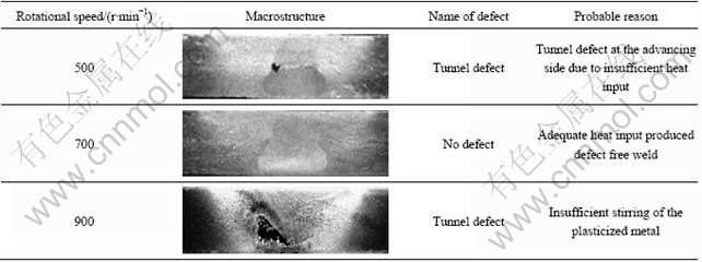
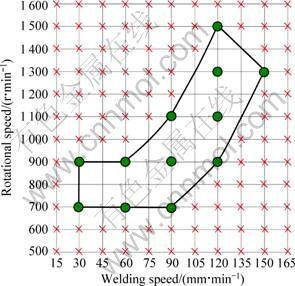
Fig. 2 Friction stir welding window based on macrostructural analysis
4 Results
4.1 Tensile properties
Transverse tensile properties of FSW joints such as yield strength, tensile strength and joint efficiency were evaluated. At constant welding speed, the tensile strength tends to decrease with the increase in the rotational speed. Similarly, at constant rotational speed, the tensile strength tends to increase with the increase in the welding speed. It was found that the tensile strength varies depending on the welding conditions used (at different regions of friction stir welding). The region of improved joint efficiency was identified and is presented in Fig. 3. The maximum tensile of 404 MPa was obtained at a rotational speed of 1 000 r/min and welding speed of 2 mm/s. It indicates that there is 12% decrease compared to that of the base metal. To identify the reason for change in tensile properties of AA2219 aluminium alloy with varying parameters, Vickers microhardness (lowest hardness distribution profile) of the joints fabricated using three different welding conditions (designated as 800-30, 1000-120 and 1400-120 welds) was analyzed and is presented. The three digit and two digit used in the designation indicate the rotational speed and welding speed respectively used to fabricate the joints.

Fig. 3 Friction stir welding window
4.2 Lowest hardness distribution profile (LHDP)
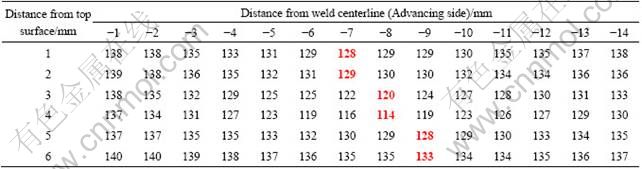
In friction stir welded joints of aluminium alloys, the failure will occur along the weakest region (the lowest hardness region). So far, the hardness profile was measured either along the mid thickness of FSW plate or along the top, center and bottom of the plate thickness to determine the lowest hardness points [7]. However, it should be pointed out that such hardness profiles could not predict the fracture behaviour of FSW aluminium alloy joints because of limited hardness points. The recent studies [8] revealed the construction of the hardness distribution profile around HAZ throughout the whole thickness of friction stir welded AA6061 aluminium alloy. It was indicated that the fracture path of welds was consistent with the lowest hardness distribution. In this study, the hardness distribution map was constructed by measuring the Vickers microhardness at an interval of 1 mm along the cross section of friction stir welded AA2219 aluminium alloy and LHDPs of 800-30, 1000-120 and 1400-120 welds are alone presented in Tables 9 to 11. From such a hardness distribution map, a LHDP was easily determined as shown in straight line in Fig. 4 due to distinct hardness difference between the LHDP and adjacent region. The increase in welding speed and decrease in rotational speed not only changed the position and inclination of the LHDPS, but also increased the hardness values of the LHDPs. The hardness values in the advancing side are relatively less compared to that in the retreating side for all the joints. At constant rotational speed, with increasing the welding speed from 30 to 120 mm/min, the distance of the LHDPs to weld center decreased, and the inclination of LHDPs to butting surface increased from ~15�� to ~45��. Similarly, at constant welding speed, increasing the rotational speed from 900 to 1 400 r/min resulted in the shift of LHDPs away from the weld center and decreased the hardness from HV 130 to HV 114. The inclination of LHDPs also decreased from ~30�� to ~10��with the increases in the rotational speed from 900 to 1 400 r/min. The LHDP of 800-30 welds is almost vertical, where the inclination of LHDPs of 1000-120 and 1400-120 welds are ~30�� and ~10��. Also the maximum hardness of HV 130 was obtained for 1000- 120 welds which is 8% and 12% greater than to that of 800-30 and 1400-120 welds, respectively. The fracture locations of all the welds are consistent with the lowest hardness distribution profile. All the specimens of the FSW joints failed on the advancing side where the lowest hardness region was observed.
Table 9 Lower distribution hardness profile for 800-30 weld (HV)

Table 10 Lower distribution hardness profile for 1000-120 welds (HV)
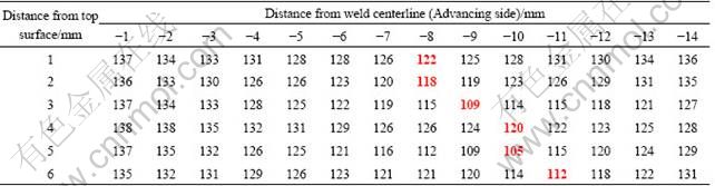
Table 11 Lower distribution hardness profile for 1400-120 welds (HV)
4.3 Microstructure
The fracture of the transverse tensile specimens (defect free) occurred at the HAZ, i.e. the weakest zone of joint, and hence, the optical micrographs of stir zone and HAZ of the three joints (i.e. 800-30, 1000-120, 1400-120) are presented in Figs. 4 and 5, respectively. The coarser grains are observed in the heat affected zone, whereas very finer grains are observed in the stir zone of the friction stir welded AA2219 aluminium alloy. The optical micrographs were taken at top, middle and bottom along the thickness direction, which are displayed in Fig. 4. From the microstructure analysis it is understood that the grains are coarser in the top region while the finer grains are observed at the bottom region. This may be due to the sufficient stirring action caused by the threaded pin at the bottom. And the top portion is coarse, which may be due to the excess heat input causing shoulder to workpiece interface. High temperature region very near to heat source (tool shoulder) leads to the formation of coarse grains due to slow cooling resulting in lowest hardness at the top region compared to the bottom region which is far away from the heat source where fast cooling results in very fine grains. However, the very fine grains were observed in 1000-120 welds while comparatively coarser grains were observed in 800-30 and 1400-120 welds.

Fig. 4 Optical micrographs of friction stir welded AA2219 aluminium alloy

Fig. 5 Optical micrographs of HAZ of friction stir welded AA2219 aluminium alloy
5 Discussion
Friction stir welding is similar to an extrusion process. During each rotation of the tool, a thin layer of plasticized material is pushed back of the tool [9]. The formation of void defect in the weld can be explained by the basic mechanics of FSW. The tool generates friction heat and causes a significant plastic deformation of the material. The weld is formed by forging the plasticized material into the cavity behind the tool from retreating side to advancing side [10]. The influence of process parameters on the weld quality can be related to the size of the cavity formed behind the tool. Based on the macrostructural analysis, the friction stir welding window is presented in Fig. 2. Higher rotational speed and lower welding speed result in excess flash formation and nugget collapse due to softening of the metal by the excess heat input during the FSW. Similarly, lower rotational speed and higher welding speed result in wormhole defect caused by insufficient heat input during the FSW. Wormhole defects were also observed at higher rotational speed and higher welding speed due to abnormal stirring. It is considered that the abnormal stirring is caused due to the higher temperature difference between the top and bottom region of weld region [11]. Based on the strength and joint efficiencies of the welds, the friction stir welding window is presented in Fig. 3. The quality of the welding also depends on the weld pitch or tool advance per revolution (refer to the ratio of welding speed to rotational speed) and can be increased by increasing the welding speed at constant rotational speed or by decreasing the rotational speed at constant welding speed. The specific weld energy of the weld increases as the weld pitch decreases. Therefore, welds with a low weld pitch are described as hot welds, while those with a relatively high weld pitch are described as cold welds. However, although the weld pitch is an important factor, weld made with the same pitch may have different energy inputs. The weld with higher welding speed and rotational speed will be in general colder than the one with lower welding speed and rotational speed. Too low weld pitch results in hotter weld which reduces the strength of joints; whereas too high weld pitch results in lower heat input which causes a tunnel at the trailing side of the tool. In FSW it is inferred that the plasticized material will flow from both sides of the pin towards the rear of the pin and may meet at the weld center. If the material does not flow fast enough to fill the cavity, a hole in the weld remain after welding and hence the weld pitch must be high enough to fill the cavity. In this investigation, the improved joint efficiencies were observed for the weld pitch values greater than 0.1 mm/r (Fig. 3). The maximum tensile strength of 404 MPa was obtained for 1000-120 weld. This may be due to the finer microstructure and higher hardness than those of the joints fabricated under other welding conditions (800-30 and 1400-120). The lower rotational speed and high welding speed result in reduced thermal exposure, thereby increasing the hardness and strength of the welds.
6 Conclusions
An age hardenable aluminum alloy, AA2219 (Al-Cu-Mn) was used as base material. Macrostructure analysis, microstructure analysis, microhardness survey, and tensile tests were carried out to characterize the FSW joints of AA2219 aluminium alloy, and the important conclusions made from this investigation are given below.
1) Defect free FSW AA2219 joints were produced under a wide range of rotational speed and welding speed. The friction stir welding window was developed to get defect free welds.
2) This window will act as a reference map to choose the best FSW process parameters to attain defect free joints in AA2219 aluminium alloy.
3) The lowest hardness distribution profiles (LHDP) with an inclination of 0��-30�� angle to the butting surface were determined by constructing hardness distribution maps around the HAZ. It was found that the inclination angle increases with the decrease in rotational speed and increase in welding speed.
References
[1] GOULD J E, FENG Z, DITZEL P. Preliminary modeling of the friction stir weld-ing process [C]//Proceedings of ICAWT, EWI. Columbus, Ohio, 1996: 297-310.
[2] GAO Y, WAGONER R H. A simplified model for heat generation during the uniaxial tensile test [J]. Metallurgical Transactions A, 1987, 18: 1001-1009.
[3] MURR L E, LIU G, McCLURE J C. A TEM study of precipitation and related microstructures in friction stir welded 6061 aluminum [J]. Journal of Materials Science, 1998, 33: 1243-1251.
[4] SATO Y S, KOKAWA H, ENOMOTO M, JOGAN S. Microstructural evolution of 6063 during friction stir welding [J]. Metallurgical and Materials Transactions A, 1999, 30: 2429-2437.
[5] RHODES C G, MAHONEY M W, BINGEL W H, SPURLING R A, BAMPTON C C. Effects of friction stir welding on microstructure of 7075 aluminum [J]. Scripta Materiala, 1997, 36(1): 69-75.
[6] JATA K V, SANKARAN K K, RUSCHAU J J. Friction-stir welding effects on microstructure and fatigue of aluminum alloy 7050-T7451 [J]. Metallurgical and Materials Transactions A, 2000, 31: 2181-2192.
[7] DAWES C J, THOMAS W M. Friction stir process welds aluminum alloys [J]. Welding Journal, 1996, 75(3): 41-45.
[8] CHEN Ying-chun, LIU Hui-jie, FENG Ji-cai. Friction stir welding characteristics of different heat-treated-state 2219 aluminium alloy plates [J]. Materials Science and Engineering A, 2006, 420: 21-25.
[9] LIENERT T J, GRYLLS R J, GOULD J E, FRASER H L. Deformation microstructures in friction stir welds on 6061-T651 [C]//Proceedings of Hot Deformation of Aluminum Alloys. TMS, 1998: 159-167.
[10] MAHONEY M W, RHODES C G, FLINTOFF J G, BINGEL W H, SPURLING R A. Properties of friction stir welded 7075 T651 aluminum [J]. Metallurgical and Materials Transactions A, 1998, 29: 1955-1964.
[11] JATA K V, SEMIATIN S L. Continuous dynamic recrystallization during friction stir welding of high-strength aluminum alloys [J]. Scripta Materiala, 2000, 43: 743-749.
AA2219���Ͻ����Ħ�����ӹ��մ��ڵĽ���
A. K. LAKSHMINARAYANAN, S. MALARVIZHI, V. BALASUBRAMANIAN
Centre for Materials Joining & Research (CEMAJOR), Department of Manufacturing Engineering,
Annamalai University, Annamalai Nagar-608 002, Tamil Nadu, India
ժ Ҫ������AA2219���Ͻ����Ħ�����ӵĹ��մ��ڡ����ò�ͬ�Ĺ��ղ�������ת�ٶȺͺ����ٶ������Ӹ����Ͻ�ͨ���Ժ��ӽ�ͷ�ĺ����ò��������������Ħ�����Ĺ��մ��ڡ�ͨ���������顢����֯�۲죬�Թ��մ��ڲ�ͬ����Ľ�ͷǿ�Ƚ��з��������ӽ�ͷ���ѵ�λ�������Ӳ�ȷֲ���ء��������Ĺ��մ��ڿ�������ѡ���ʵ��Ĺ��ղ�������ø�������AA2219���Ͻ����Ħ�����ӡ�
�ؼ��ʣ�����Ħ�������մ��ڣ����Ͻ����Ӳ�ȷֲ�������ǿ��
(Edited by YUAN Sai-qian)
Corresponding author: A. K. LAKSHMINARAYANAN; Tel: +91-4144-239734; Fax: +91-4144-238080; E-mail: akln2k2@yahoo.com
DOI: 10.1016/S1003-6326(11)61018-2
Abstract: A friction stir welding window was developed for effective joining of AA2219 aluminium alloy. Joints were fabricated using different combination of process parameters such as rotational speed and welding speed. Based on macrostructural analysis, the friction stir welding window was constructed. The strength values of joints at different regions of friction stir welding window were analyzed using tensile properties, microstructural studies, and the fracture location of joints was correlated with the lowest hardness distribution profiles. These windows will act as reference maps for selecting appropriate friction stir welding process parameters to get good quality welds of AA2219 aluminium alloys.
