
Trans. Nonferrous Met. Soc. China 24(2014) 462-469
Numerical analysis of coupled finite element with element-free Galerkin in sheet flexible-die forming
Zhong-jin WANG, Bin-xian YUAN
School of Materials Science and Engineering, Harbin Institute of Technology, Harbin 150001, China
Received 7 February 2013; accepted 9 August 2013
Abstract:
A numerical method for coupled deformation between sheet metal and flexible-die was proposed. Based on the updated Lagrangian (UL) formulation, the elastoplastic deformation of sheet metal was analyzed with finite element method (FEM) and the bulk deformation of flexible-die was analyzed with element-free Galerkin method (EFGM). The frictional contact between sheet metal and flexible-die was treated by the penalty function method. The sheet elastic flexible-die bulging process was analyzed with the FEM-EFGM program for coupled deformation between sheet metal and bulk flexible-die, called CDSB-FEM-EFGM for short. Compared with finite element code DEFORM-2D and experiment results, the CDSB-FEM-EFGM program is feasible. This method provides a suitable numerical method to analyze sheet flexible-die forming.
Key words:
sheet flexible-die forming; finite element method; element-free Galerkin method; coupling; aluminum alloy;
1 Introduction
With the development of industrial technology, conventional rigid die forming technology faces more challenges to form complex-shaped parts and difficulty to form lightweight materials, such as magnesium, aluminum and titanium alloy [1,2]. Compared with conventional sheet forming technology, sheet metal flexible-die forming is one of the efficient and potential techniques to solve existing problems. They have a good application on sheet metal forming in aerospace and automotive industry [3-7].
The numerical simulation is a powerful tool to analyze the sheet metal forming processes. While, in sheet metal flexible-die forming process, there is a coupled deformation between sheet metal and flexible-die, which raises some limitations and difficulties for existing commercial softwares. Hence, several simplified approaches have been conducted to simulate the sheet metal flexible-die forming process approximately. For example, viscous medium flexible-die for viscous pressure forming was treated to be an incompressible fluid that could not account for the viscoelastic effect of the viscous medium [8]. Especially, during the finite element analysis of sheet metal flexible-die forming, deformation of the flexible-die is very large and often leads to distorted meshes, thus it needs remeshing [9]. Remeshing, which is a bottleneck problem for finite element method, not only increases computational efforts significantly, but also results in a degradation of the overall accuracy. Furthermore, hexahedron element meshes have been proved to be superior to tetrahedron element meshes in terms of analysis accuracy, amount of meshes, distortion resistance and regeneration times. This turns hexahedra an attractive choice for the numerical analysis of bulk forming. While, none of the existing methods has been proven to be an all-encompassing algorithm and each has drawbacks to their use.
In the past decades, a node based numerical method, called meshless method, has been developed [10,11]. It discretizes a continuum body by a finite number of nodes, and the displacement field is interpolated under these nodes without the aid of an explicit mesh. Meshless methods require no costly mesh generation and remeshing. This characteristic can eliminate mesh distortion unavoidable in FEM. Based on these advantages mentioned above, meshless method can simulate bulk forming processes more effectively, especially when deformation is appreciable [12].
In this work, the deformation of sheet metal was analyzed by shell element based on the Mindlin shell theory, and the flexible-die was analyzed based on a common meshless method called element-free Galerkin method (EFGM). Frictional contact between the flexible-die and the sheet metal is treated by a node-point contact method. The R-minimum strategy is introduced to deal with the contact condition at the interface in the solution algorithm. A CDSB-FEM-EFGM program for coupled deformation between sheet metal and bulk flexible-die is developed based on the above theories. Numerical examples are presented to show the validity of the developed program.
2 Basic theories of finite element method and element-free Galerkin method
2.1 Mindlin thick-shell element model
Based on the Mindlin-Reissner theory, a 2-node axisymmetric degenerated shell element was employed for the finite element analysis of sheet metal [13], as shown in Fig. 1, where (r(x)Oz) is the global Cartesian coordinate system, (��, ��) is the local coordinate system, ui and wi represent the displacements of node i, and fi denotes the rotation angel of node i to the normal of mid-surface. The displacement of an arbitrary point in the element can be expressed by
 (1)
(1)
where ue is the nodal displacement vector of the element; N is the shape function matrix of the element; and
 ,
,  ;
;
 ;
;

 , and Ni(��) is the shape function of the element; tsi is the thickness of node i.
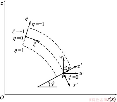
Fig. 1 2-node Mindlin thick-shell element
2.2 Element-free approximation
In the element-free Galerkin method, the displacement u(x) at point x is approximated by the moving least-squares (MLS) interpolants as
 (2)
(2)
where coefficients ai(x) are functions of x, m is the order of basis function pT(x) and pi(x) is monomial in the space coordinates x=[x, y]T. A linear basis in a two- dimensional domain is provided by
 (3)
(3)
and a quadratic basis by
 (4)
(4)
In the moving least-squares interpolants, coefficients ai(x) are obtained by minimizing
 (5)
(5)
where
 ;
;

and w(x-xI) is the weight function; 
The stationarity of Eq. (5) with respect to a leads to
 (6)
(6)
Where
 and
and  .
.
Substituting Eq. (6) into Eq. (2) yields
 (7)
(7)
where

Unlike the finite element method, the nodal value of the interpolation function uh(x) is not equal to the nodal value u(x) at the point x, namely uh(x)��u, so the essential boundary condition should be imposed by Lagrange multipliers or penalty method [10].
3 Coupled formulation of FEM-EFGM
The updated Lagrangian (UL) formulation was employed to describe the coupled deformation between sheet metal and flexible-die. The configuration at time t is adopted as the reference state to evaluate the deformation from time t to t+��t. The principle of virtual work-rate principle for the coupled deformation with updated Lagrange formulation is represented as [14]

 (8)
(8)
where V1 and V2 are body domains for sheet metal and flexible-die at time t, respectively; S denotes the surface boundary area for two bodies;  is the applied external surface force rate;
  is the Jaumann rate of Cauchy stress ��ij; Lij is the velocity gradient; Dij is the symmetric part of Lij;
  and
and  are the contact interfaces of sheet metal and flexible-die;
  is the surface force rate at contact surface
  (��=1,2).
3.1 Constitutive model
In this work, an elastoplastic material model is chosen for describing the deformation of sheet metal. The equivalent stress-equivalent plastic strain relation is represented by Swift equation:
 (9)
(9)
where  is the equivalent stress; ��0 is the initial yielding strain;
  represents the equivalent plastic strain; K is the material strength coefficient and n is the work hardening exponent.
In the local coordinate system x��O��y��, the constitutive equation can be expressed as follows:

 (10)
(10)
where represents the Jaumann rate of Cauchy stress; lkl is the velocity gradient in the local coordinate system;  denotes the elastoplastic constitutive matrix; E and �� are the elastic modulus and Poisson ratio, respectively; ��ij is the Kronecker delta tensor;
  corresponds to the slope of the equivalent stress divided by plastic strain
  ;
;  is the deviatoric stress components.
3.2 Formulation of contact problem
Aiming at the characteristics of coupled deformation between sheet metal and flexible-die, a slave-master node-to-point contact element is employed to treat the frictional contact between these two bodies. The flexible-die is defined as slave body and the sheet metal is master body. A slave node on the slave body and its contact point on the master segment compose a contact point pair. Therefore, the total contact force virtual power rates on the contact surface are the summation of contact force virtual power rate of each contact point pair.
 (11)
(11)
where nc is the number of contact point pairs,  is the equivalent contact force virtual rate of each contact point pair at time t+��t and can be calculated by
 (12)
(12)
where  is the relative nodal velocity; Nc is the shape function; t+��t�� is the coordinate transformation matrix at time t+��t.
The Coulomb friction model and penalty function method are chosen for solid flexible-die forming of sheet metal, the contact force rate on the contact surface can be expressed by
 (13)
(13)
where  is the contact force rate at the local coordinate system,
  is the relative velocity between the contact point pair (��=1, 2) and
  is the penetration rate in the normal direction.

where ��t is the tangential penalty factor, ��n is the normal penalty factor,  is the friction coefficient, and when the element is in the adhesive state ��=0, the element slide ��=1.
 (14)
(14)
where  is the value of peneration rate in the normal direction.
Substituting Eqs. (13) and (14) into Eq. (12), we get
 (15)
(15)
It can be written in the matrix form:
 (16)
(16)
where

Substituting Eqs. (1), (7), (10) and (16) into Eq.(8), the equilibrium equation is represented in the following form:
 (17)
(17)
where K is the total stiffness matrice of sheet metal deformation and bulk flexible-die deformation; Kc is the contact stiffness matrix between the sheet metal and the bulk flexible-die; ��U denotes the displacement increment of the nodes; ��F is the external force increment on the boundary area; ��Fc is the contact force increment on the contact surface.


where n1 is the element number of the sheet metal, n is the nodes number of the flexible-die, and �� is penalty coefficient that imposed the essential boundary condition of flexible-die.
3.3 Time integration algorithm
Because of strong non-linear during coupled deformations between sheet metal and bulk flexible-die in sheet metal flexible-die forming, a static-implicit algorithm may face the disadvantage of misconverged iteration. Unlike the static-implicit algorithm, the static-explicit algorithm controls the size of the time step to keep the material state and contact state stable in each loading step. In this work, a static-explicit algorithm called R-minimum strategy proposed by YAMADA and YOSHIMURA [15] has been adopted. It is suggested that all rates in Eq.(17) can be considered constant within a sufficiently small time increment from t to t+��t as long as there are no radical changes of materials or contact state take place. The increment of each loading step is controlled by the smallest value of the following five controlled parameters r1-r5 [16]:
1) For each elastic element, r1 is calculated to ascertain the equivalent stress just reaches the current yield stress;
2) For each element, r2 is obtained by the ratio of the default maximum strain increment 0.002 to the strain increment;
3) For each element, r3 is calculated by the defaulted maximum rotation increment 0.5 to the rotation increment;
4) For each node of flexible-die on contact surface, r4 is calculated such that the free nodes just contact the sheet metal or the contact nodes just separate from the contact surface;
5) For each contact node of flexible-die body, r5 is obtained to ensure the contact state just changes from sticking to sliding or from sliding to sticking.
The minimum value of the factors above is defined as rmin. By multiplying ��u by the rmin, we obtain the time step increment rmin��u.
4 Numerical examples
4.1 Sheet metal flexible-die bulging
In order to verify the reliability of the developed CDSB-FEM-EFGM code based on the above theory, the simulation of sheet flexible-die bulging of Al1060 sheet is conducted. Figure 2 shows the numerical analysis model of coupled deformation between sheet metal and flexible-die, which is an axisymmetric model. The flexible-die is a cylinder with height of 40.0 mm and radius of 50.0 mm, and is discretized with 456 nodes. The elastic modulus and Poisson ratio of the elastic flexible-die are 10.0 MPa and 0.49, respectively. The Al1060 sheet is discretized with 33 two-node Mindlin axisymmetric shell elements and its property parameters are listed in Table 1. In order to compare CDSB-FEM- EFGM with FEM results, the similar FEM analysis model is established by DEFORM-2D, and the initial model is shown in Fig. 3. Flexible-die is discretized with 500 four-node isoparametric elements.
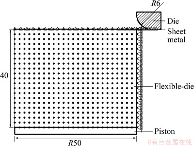
Fig. 2 Numerical analysis model of coupled deformation between sheet metal and flexible-die
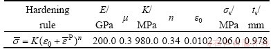
Table 1 Property parameters of Al1060 sheet
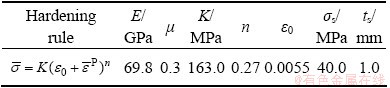
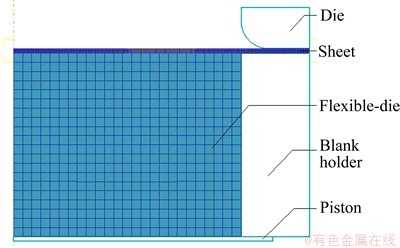
Fig. 3 Finite element analysis model of coupled deformation between sheet metal and flexible-die
Figure 4 shows the coupled deformations of both sheet metal and flexible-die with bulging height h=19.5 mm by proposed FEM-EFGM method and DEFORM-2D. A good agreement between them is observed. During finite element analysis, the meshes of flexible-die around the die outlet distort and need to remesh in the next incremental step, as shown in Fig. 5. While, because the flexible-die is discretized through meshless method in developed CDSB-FEM-EFGM program, it is free of the trouble caused by mesh distortion.
Both the radial and circumferential strain distributions of the sheet obtained by developed program and DEFORM-2D for the bulging height of 30.0 mm are shown in Fig. 6. It can be seen that both the radial and circumferential strains are increasing with the rise of the bulging height. The strain distribution trends and values obtained by the proposed methods and DEFORM-2D are similar. The thickness of the sheet with bulging height is shown in Fig. 7. It is obvious that CDSB-FEM-EFGM results are in good agreement with FEM results.
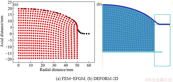
Fig. 4 Coupled deformation of sheet metal and flexible-die with bulging height of 19.5 mm
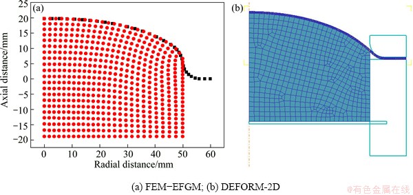
Fig. 5 Coupled deformation of sheet metal and flexible-die with bulging height of 19.7 mm
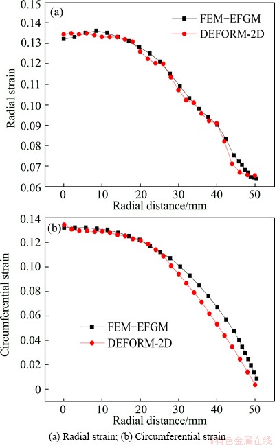
Fig. 6 Strain distribution of sheet metal with bulging height of 30.0 mm
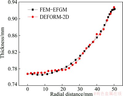
Fig. 7 Thickness distribution of sheet metal with bulging height of 30.0 mm
4.2 Polyurethane rubber bulging of sheet metal
The second example is to analyze the sheet metal polyurethane bulging process. In this example, sheet metal polyurethane bulging experiments of 1Cr18Ni9Ti sheet were carried out. Figure 8 shows the sketch of the polyurethane bulging. Circular meshes with the diameter of 2.0 mm are printed on the surface of sheet before experiments. Figure 9 shows the polyurethane rubber used in sheet metal polyurethane bulging and the stress-strain relationship curve of polyurethane is shown in Fig. 10. The sheet is clamped between blank holders to prevent any material from drawing-in. Then the piston was pushed to employ the pressure of polyurethane rubber on sheet blank, and the sheet deforms in a pure stretching condition. After the experiments, the strain state of deformed sheet metal can be obtained through measuring the shape of deformed meshes. Figure 11 shows the specimen with bulging heights of 15.0, 20.0, 30.0 and 35.0 mm.
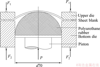
Fig. 8 Sketch of sheet metal polyurethane bulging test
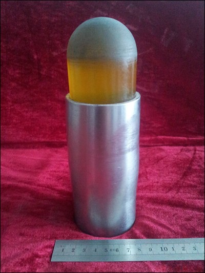
Fig. 9 Polyurethane rubber used in experiment
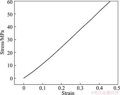
Fig. 10 Relationship between stress and strain of polyurethane
Polyurethane rubber bulging is simulated by the developed CDSB-FEM-EFGM program and the calculated results are compared with experimental measurements. The numerical analysis model of sheet metal polyurethane bulging is shown in Fig. 12. Since the geometry of the polyurethane bulging is axisymmetric, only a section of the geometry was analyzed. The diameter of die hole is 70.0 mm. The diameter of sheet blank is 90.0 mm and its initial thickness is 0.978 mm. The mechanical properties of 1Cr18Ni9Ti sheet are listed in Table 2. The finite element discretization includes 51 two-node Mindlin axisymmetric shell elements to model the sheet metal. The edge of sheet blank is constrained at all degrees of freedom. The polyurethane rubber is discretized with 546 nodes. The friction coefficient between polyurethane rubber and sheet metal is 0.1.
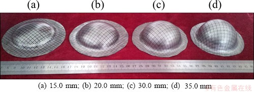
Fig. 11 Sample formed by polyurethane rubber bulging with bulging heights
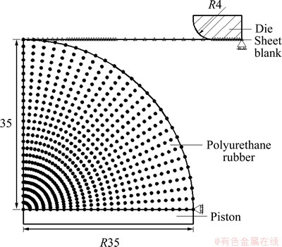
Fig. 12 Numerical analysis model of sheet metal polyurethane bulging
Table 2 Property parameters of 1Cr18Ni9Ti sheet
The comparisons of the calculated radial and circumferential strains, thickness distribution of bulge specimen and experimental ones at the dome height of 15.0, 20.0, 30.0 and 35.0 mm are shown in Figs. 13 and 14. It can be seen that both the radial and circumferential strains reach the maximum values at the dome center and decrease along the radius direction. The same conclusion can be obtained for thickness distribution, and the largest thinning of sheet occurs at dome center. From the comparison of numerical simulation results and experimental data, we can find that both of them have the similar tendency. The calculated radial and circumferential strains of specimen around the entrance of the die are a little bigger than those of experimental measurements. The difference between experimental data and numerical simulations can be attributed to mesh dividing of the sheet metal and the effect of die on the sheet.
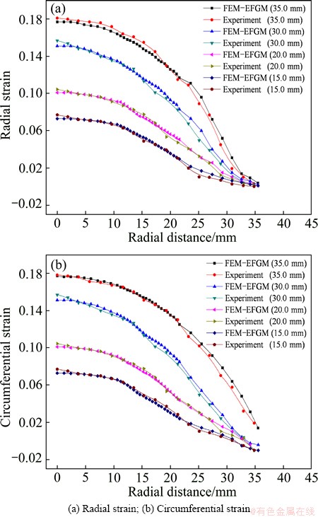
Fig. 13 Strain distribution of sheet metal with different bulging heights
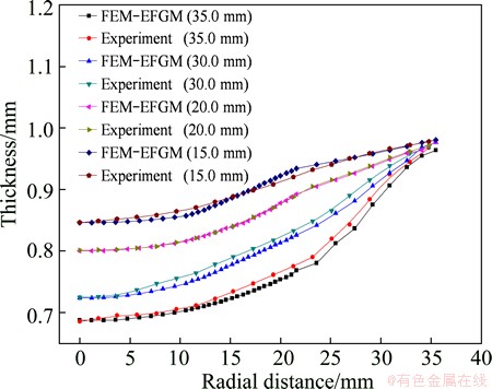
Fig. 14 Thickness distribution of sheet metal with different bulging heights
5 Conclusions
1) The element-free Galerkin method is introduced into the analysis of the sheet metal flexible-die forming, a numerical analysis method for coupling the deformation of sheet metal and flexible-die is developed.
2) The sheet flexible-die bulging process is analyzed with the developed CDSB-FEM-EFGM program. The strain and thickness distributions obtained by the CDSB-FEM-EFGM are compared with those by DEFORM-2D and experiments in detail. Clearly, the CDSB-FEM-EFGM simulation results are consistent with those obtained by DEFORM-2D and experiments. It shows that the FEM-EFGM model and key techniques for frictional contact are effective and accurate. With the introduction of element-free Galerkin method, the presented method avoids the need of expensive meshing and remeshing procedures unavoidable in conventional FEM. Especially, this method could be further developed to analyze the effect of mechanical properties (such as elastic, viscoelastic and visco-elastoplastic) of flexible- die on sheet metal in sheet flexible-die forming.
References
[1] SCHMOECKEL D, HIELSCHER C, HUBER R, GEIGER M. Metal forming of tubes and sheets with liquid and other flexible media [J]. Annals of CIRP, 1999, 48: 497-513.
[2] PENG L F, HU P, LAI X M, MEI D Q, NI J. Investigation of micro/meso sheet soft punch stamping process [J]. Simulation and Experiments, 2009, 30: 783-790.
[3] SIEGERT K. Recent developments in hydroforming technology [J]. Journal of Materials Processing Technology, 2000, 98: 251-258.
[4] WANG Z J, WANG X Y, WANG Z R. Viscous pressure forming (VPF) of corrugated thin-walled sheet part with small radius [J]. Journal of Materials Processing Technology, 2004, 145: 345-351.
[5] MONTAZEROLGHAEM H, FARZIN M, TEHRANI A F. Theoretical and experimental investigation of viscous pressure forming for manufacture of miniature parts [C]//Proceeding of the 9th International Conference Technology of Plasticity. Gyeongiu, Korea, 2008: 1134-1139.
[6] RAMEZANI M, RIPIN Z M, AHMAD R. Computer aided modelling of friction in rubber-pad forming process [J]. Journal of Materials Processing Technology, 2009, 209: 4925-4934.
[7] LIU Y X, HUA L, LAN J, WEI X. Studies of the deformation styles of the rubber-pad forming process used for manufacturing metallic bipolar plates [J]. Journal of Power Sources, 2010, 195: 8177-8184.
[8] MUSTAF A, JIANG H, SRIKANTH K. Hydroforming of sheet metal using a viscous pressure medium [J]. Journal of Materials Processing Technology, 2004, 146: 97-107.
[9] LIU Jian-guang, WANG Zhong-jin, SONG Hui. Numerical simulation of sheet flexible-die forming process [J]. Materials Science and Technology, 2008, 16(3): 430-434. (in Chinese)
[10] BELYTSCHKO T, LIU Y Y, GU L. Element-free Galerkin methods [J]. International Journal for Numerical Methods in Engineering, 1994, 37: 229-256.
[11] ZHANG Xiong, LIU Yan, MA Shang. Meshfree methods and their applications [J]. Advances in Mechanics, 2009, 39(1): 1-36. (in Chinese)
[12] GUAN Y J, WU X, ZHAO G Q, LU P. A nonlinear numerical analysis for metal-forming process using the rigid-(visco)plastic element-free Galerkin method [J]. International Journal of Advanced Manufacturing Technology, 2009, 42: 83-92.
[13] WANG Z J, LIU J G. Sectional finite element analysis of coupled deformation between elastoplastic sheet metal and visco-elastoplastic body [J]. Acta Mechanica Solida Sinica, 2011, 24: 153-165.
[14] MCMEEKING R M, RICE J R. Finite element formulations for problems of large elastic-plastic deformation [J]. International of Solids and Structures, 1975, 11: 601-616.
[15] YAMADA Y, YOSHIMURA N. Plastic stress-strain matrix and its application for the solution of elastic-plastic problem by the finite element method [J]. International Journal of Mechanical Science, 1968, 10: 343-354.
[16] LIU D K. Finite-element simulation of hole-flanging process of circular sheets of anisotropic materials [J]. International Journal of Mechanical Science, 1996, 38: 917-933.
�����ģ���ι�������Ԫ��������٤�ɽ���ϵ���ֵ����
���ҽ�Ԭ����
��������ҵ��ѧ ���Ͽ�ѧ�빤��ѧԺ�������� 150001
ժ Ҫ�����һ�ְ�ı��κ���ģ���������ϵ���ֵ�������������ڸ��µ���������(UL)��ʽ����ĵĵ����Ա��β�������Ԫ��(FEM)��������ģ��������β���������٤�ɽ�(EFGM)��������ĺ���ģ֮���Ħ���Ӵ�ͨ���������������������ÿ���������Ԫ-����������㷨����(CDSB-FEM-EFGM)������ĵ�����ģ���ι��̡�ͬ����Ԫ����DEFORM-2D�õ�����ֵ���Լ�ʵ������ȣ���֤���������������Ч�ԡ����ַ���Ϊ���������ģ�����ṩ��һ���ʺϵ���ֵ������
�ؼ��ʣ������ģ���Σ�����Ԫ����������٤�ɽ���ϣ����Ͻ�
(Edited by Xiang-qun LI)
Foundation item: Project (51275130) supported by the National Natural Science Foundation of China
Corresponding author: Zhong-jin WANG; Tel: +86-451-86413365; E-mail: wangzj@hit.edu.cn
DOI: 10.1016/S1003-6326(14)63083-1
Abstract: A numerical method for coupled deformation between sheet metal and flexible-die was proposed. Based on the updated Lagrangian (UL) formulation, the elastoplastic deformation of sheet metal was analyzed with finite element method (FEM) and the bulk deformation of flexible-die was analyzed with element-free Galerkin method (EFGM). The frictional contact between sheet metal and flexible-die was treated by the penalty function method. The sheet elastic flexible-die bulging process was analyzed with the FEM-EFGM program for coupled deformation between sheet metal and bulk flexible-die, called CDSB-FEM-EFGM for short. Compared with finite element code DEFORM-2D and experiment results, the CDSB-FEM-EFGM program is feasible. This method provides a suitable numerical method to analyze sheet flexible-die forming.
