
Trans. Nonferrous Met. Soc. China 22(2012) s408-s415
Warm hydroforming of magnesium alloy tube with large expansion ratio within non-uniform temperature field
LIU Gang, ZHANG Wen-da, HE Zhu-bin, YUAN Shi-jian, LIN Zhe
National Key Laboratory for Precision Hot Processing of Metals, Harbin Institute of Technology, Harbin 150001, China
Received 28 August 2012; accepted 25 October 2012
Abstract:
According to warm hydroforming with poor thickness uniformity and low expansion ratio, a new approach named warm hydroforming with non-uniform temperature field was presented. Warm hydroforming die with nonuniform temperature field was designed and temperature field along tube axis was established with differential temperature gradient. Then, the effect of the temperature difference between the forming zone and the feeding zone on thickness uniformity along the part axis was studied in a certain loading path. Thickening of the feeding zone decreases and the thickness uniformity of tubular part is improved by selecting appropriate temperature difference, for this experiment, suitable temperature difference is 150 ��C. Further, the effect of the preform shape formed by warm hydroforming on the limit expansion ratio of magnesium alloy tube was studied, using preform with wrinkles and preform with expansion ratio of 35% hydroformed by using differential temperature. The limit expansion ratio reaches 66.2% by using the preform with expansion ratio of 35%.
Key words:
magnesium alloy; warm hydroforming; nonuniform temperature field; limit expansion ratio;
1 Introduction
As typical light-weight structural materials with high specific strength [1,2], magnesium alloy sheets and tubes have been applied in automotive and aircraft industries to meet the demand of fuel saving. Therefore, magnesium alloy has a good application prospect [3]. Due to the poor room temperature plasticity of magnesium alloy [4,5], the complex structural parts are difficult to form [6,7]. Hydroforming at the elevated temperature can improve the plasticity and enhance the forming limit of these materials [8-10]. Warm hydroforming has a feature that thickness uniformity is poor, with high thinning ratio of the forming zone and high thickening ratio of the feeding zone [11]. The reason of such thickness distribution is that at a high temperature, the yield strength of tube materials is lower, while the friction coefficient value between the tube and the die is high, so that under the effects of the axial force generated by axial feeding and the friction force, upsetting deformation occurs at the end of the tube, and then induces thickening [12,13]. Therefore, the material is difficult to be pushed into the die cavity, and the expansion ratio of component is low [14]. Poor formability limits the application of tube hydroforming of magnesium alloy [15]. Consequently, the serious nonuniformity of thickness weakens the light-weight effect of applying magnesium alloy and induces material waste.
In this work, hydroforming of magnesium alloy tubular parts with nonuniform temperature fields was studied to provide a method of improving thickness uniformity and enhancing expansion ratio by controlling behaviors of plastic deformation based on the effects of temperature field on mechanical properties of materials.
2 Experimental setup and FE model
2.1 Experimental setup
The principle of warm hydroforming with nonuniform temperature field is shown in Fig. 1. The temperature gradient of tube blank can be realized through controlling the die temperature in the different zones separately, to obtain lower temperature in the feeding zone (T1) and higher temperature in the forming zone (T2). First, with higher yield strength at lower temperature, plastic deformation can be postponed and restrained in the feeding zone so that thickening of tube ends can be restrained. Second, at lower temperature, the friction coefficient in the forming zone might be reduced to promote the materials flowing into the die cavity during axial feeding. Experimental setup is shown in Fig. 1. The tube blank can be heated by continuously flowing heated oil medium. Temperature sensors are put into the die and the tube blank to detect the temperature and the results are fed back to the central control unit. Cooling water is used to keep the feeding zone temperature of the die lower than that of the forming zone to realize the designed temperature field of the tube blank.

Fig. 1 Principle of warm hydroforming with nonuniform temperature fields
2.2 FE model
The extruded AZ31 magnesium alloy is used in simulation and experiments. The outside diameter and thickness of the original tube blank are 65 mm and 2 mm, respectively. Because of the symmetrical shape, half model is chosen. Finite element analysis is carried out by using software Abaqus 6.10. Finite element model is shown in Fig. 2. Viscoplastic model is used in tube blank, and the die is set as a rigid body, using surface-to-surface contact between the tube blank and the die. Friction coefficient in forming zone is 0.15 and it is 0.1 in the feeding zone because its temperature is lower than that in the forming zone. Finite element solver using explicit function modules, the tube blank and die are both meshed by 4-node thermally coupled doubly curved thin or thick shell, reduced integration, hourglass control, finite membrane strains (S4RT). Figure 3 shows the true stress curves versus true strain at different strain rates and different temperatures.
3 Results and analysis
The effects of temperature differences between the forming zone and the feeding zone on formability and thickness distribution are mainly investigated. First, using the die with the expansion ratio of 35%, experiments were carried out to obtain a reasonable loading path and the best temperature difference. Second, using the die with the expansion ratio of 70%, the effect of preform shape on the limit expansion ratio of magnesium alloy tube was studied through experiments.

Fig. 2 FEM model

Fig. 3 True stress��true strain curves of AZ31 magnesium alloy tube
3.1 Effect of loading paths on formability
To form a tubular component with a large expansion ratio, a loading path with a matching relation between internal pressure and axial feeding was selected according to experiments. Three different loading paths were used in the experiments, as shown in Fig. 4. Under the same temperature conditions, the forming zone temperature of 240 ��C and the feeding zone temperature of 90 ��C, the experimental results from different loading paths are shown in Figs. 5-7.

Fig. 4 Loading paths
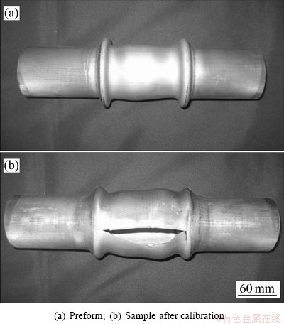
Fig. 5 Samples from loading path 1

Fig. 6 Samples from loading path 2

Fig. 7 Samples from loading path 3
The experimental results from loading path 1 are shown in Fig. 5. When the axial feeding is completed at pressure of 5.5 MPa, sharp wrinkles occur at both ends of the forming zone under low internal pressure, and then bursting occurs during calibration for uneven material distribution in the forming zone. The experimental results from loading path 2 are shown in Fig. 6, in which the axial feeding is executed at pressure of 7 MPa. The feeding material is distributed evener than that for the loading path 1, so that the workpiece is nearly formed, only with a tiny crack along the axial direction. Figure 7 shows the experimental results when the temperature difference is 150 ��C. With the matching relation between internal pressure and axial feeding, preform with wrinkles was formed firstly, as shown in Fig. 7(a), and then the component with expansion ratio of 35% was obtained after calibration, as shown in Fig. 7(b).
3.2 Effect of forming zone temperature on formability
To reveal the effect of the forming zone temperature on formability, the loading path 3 was applied to the experiments. The temperature difference was fixed at 150 ��C, and only the temperature of the forming zone was changed for different experiments to realize the temperature of 200, 220 and 240 ��C, respectively.
Figure 8 shows the experimental results when the forming zone temperature is 200 ��C. Bursting occurs during calibration and the maximum diameter is 86.4 mm.
Figure 9 shows the thinning ratio distribution of different forming zone temperature. The thickness distribution from the forming zone temperature 240 ��C is evener.

Fig. 8 Samples from forming zone temperature of 200 ��C

Fig. 9 Thinning ratio distribution along axial samples from different forming zone temperature
3.3 Effect of temperature difference on thickness distribution
To reveal the effect of temperature difference on thickness distribution, the loading path 3 was applied to the experiments. The temperature of the forming zone was fixed at 240 ��C, and only the temperature at the ends of the tube blanks was changed for different experiments to realize the temperature differences of 130, 150 and 170 ��C between the forming zone and the feeding zone.
First, the effect of temperature difference on wrinkling behavior was studied. The experimental results from different temperature differences are shown in Fig. 10. It can be seen that useful wrinkles are obtained before calibration. The wrinkles with similar shape and amount might be useful to increase the expansion ratio limit and induce the wall thickness distribution in warm tube hydroforming with nonuniform temperature field.

Fig. 10 Samples obtained from different temperature differences
Figure 11 shows the experimental samples in cross section for the three kinds of temperature differences, in which the maximum thickening positions and thinning positions for every sample are pointed out. The thinning ratio difference on the sample for temperature difference of 130 ��C has the biggest value of 21.6%, but 13.3% and 11.6% for temperature differences of 170 ��C and 150 ��C, respectively, as listed in Table 1. It illustrates that the thickness distribution is more even when temperature difference is 150 ��C.

Fig. 11 Cross sections of samples obtained from different temperature differences ��T
Table 1 Thickness variation ratios for different temperature differences

For temperature difference of 130 ��C, because the yielding stress is low at high temperature (feeding zone temperature of 110 ��C), the thickening ratio of feeding zone is more than that at temperature difference of 170 ��C (feeding zone temperature of 70 ��C). Meanwhile, since the material of the transition zone is deformed easily, which induces wrinkles in the transition zone so that less material is fed into the forming zone, consequently causes the bigger thinning ratio at temperature difference of 130 ��C. For temperature difference of 150 ��C, although thickening of the feeding zone is close to that of temperature difference of 170 ��C, deformation in the forming zone is more uniform so that the maximum thinning ratio of the forming zone is smaller than that of 170 ��C, which is the reason that the thickness distribution from temperature difference of 150 ��C is evener.
By comparison of experimental results, both thickening of the feeding zone and thinning of the forming zone are serious when temperature difference is small. However, the deformation non-uniformity in the forming zone becomes more significant when temperature difference is too large. Therefore, the temperature difference has an important effect on warm hydroforming with nonuniform temperature field. For this experiment, the suitable temperature difference is 150 ��C.
3.4 Research on limit expansion ratio
Limit expansion ratio shows the possibility that a process could be used for practical applications. As a structure material with poor formability at room temperature, the limit expansion ratio of magnesium tube is very small in conventional processes.
Further experiments were carried out to explore the potential to increase the limit expansion ratio by warm hydroforming with non-uniform temperature field. First of all, using the die with expansion ratio of 70%, the temperature of the forming zone was fixed at 240 ��C and temperature difference of 150 ��C, the maximum expansion ratio reached only 51.5%, as shown in Fig. 12(a). Using preform with wrinkles shown in Fig. 7(a), the maximum expansion ratio reached 62.5%, as shown in Fig. 12(b). Using preform with expansion ratio of 35% shown in Fig. 7(b), the limit expansion ratio reached 66.2%, as shown in Fig. 12(c).

Fig. 12 Experimental results
4 Effect of preform shape on limit expansion ratio
Finite element simulations were conducted to analyze the deformation during hydroforming. Figure 13 shows the thinning ratio distribution for different preformed billets. Figure 14 shows the simulated results of thinning ratio distribution that the limit expansion ratio reaches 66.2% by using different preforms.
It can be seen from the simulated results that, the thinning ratio of workpiece hydroformed by using preform with wrinkles reaches 30.5%, while the thinning ratio of workpiece hydroformed by using preform with expansion ratio of 35% reaches 25.5%.
Figure 15 shows the equivalent strain distribution hydroformed by using different preformed billets. It can be seen that the maximum deformation occurs at both ends of the forming zone. However, the maximum strain on the two workpieces has a great difference. For the workpiece hydroformed by preform with wrinkles, the maximum strain is 1.68, which will induce earlier crack. For the workpiece hydroformed by preform with expansion ratio of 35%, the maximum strain is only 0.95. It indicates that the latter preform is much better than the former one for forming a large expansion component.

Fig. 13 Thinning ratio distribution of preform
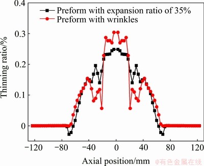
Fig. 14 Thinning ratio distributions of workpieces hydroformed by using different preforms

Fig. 15 Simulated equivalent strain distributions at temperature difference of 150 ��C
Figure 16 shows the strain paths of typical points in the second step hydroforming process. With different preforms, obvious differences appear for the three selected points (A, B and C in Fig. 7(a)). The most significant difference appears at point C located in the top of the wrinkle near the transition zone. The strain state from the preform with wrinkles is tensile in both hoop and axial direction. However, the strain state from the preform with expansion ratio of 35% is tensile in hoop direction, but compressive in axial direction.

Fig. 16 Strain paths of typical points
Therefore, the thinning of the workpiece from the preform with expansion ratio of 35% is smaller than that from the preform with wrinkle during the second hydroforming process.
At the bottom of the wrinkle (point B), though the strain states from the two preforms are both hoop tensile strain and axial compressive strain throughout the hydroforming process, there is large difference in the absolute value of thickness strain that can be calculated according to the incompressibility principle. For point B of preform with wrinkles, the final hoop strain is 0.45 and the value of axial strain is only -0.23, so the thickness strain is -0.22. For point B of preform with expansion ratio of 35%, the final axial strain is only -0.09 with hoop strain of 0.2 and the thickness strain of -0.11. By contrast, it is clear that the thickness from the preform with wrinkles is smaller than that from the preform with expansion ratio of 35%. For the point A, the similar result could be found due to different axial strains for the two kinds of preforms. The results illustrate that the material can be distributed to the more appropriate position during the formation of the preform with expansion ratio of 35%, and induce the better strain state during the second step hydroforming, consequently results in the larger expansion limit.
5 Conclusions
1) According to the effect of temperature difference on thickness uniformity of hydroformed tubular parts with expansion ratio of 35%, the best temperature difference is 150 ��C. Larger temperature difference induces non-uniform deformation in the forming zone, but lower temperature difference induces thickening at the feeding zone near the tube ends.
2) In one step warm hydroforming with differential temperature field, the limit expansion ratio is only 51.5%. Within two-step warm hydroforming, the limit expansion ratio of the magnesium alloy tube can be enhanced obviously through preforming. The limit expansion ratio reaches 66.2% by using preform with expansion ratio of 35%.
3) It can be concluded that with different preforms, the materials can be distributed into different positions and induce different strain states during the second hydroforming process. Using the preform with expansion ratio of 35%, the strain states in the workpiece are kept as compressive in axial direction and tensile in hoop direction, and then the absolute value of compressive strain in thickness direction is small so that the early bursting can be avoided to realize a larger expansion limit.
References
[1] MUSTAFA K K. Magnesium and its alloys applications in automotive industry [J]. International Journal of Advanced Manufacturing Technology, 2007, 39(9-10): 851-865.
[2] LUO A A. Magnesium: Current and potential automotive applications [J]. Journal of the Minerals, Metals and Materials Society, 2002, 54(2): 42-48.
[3] KULEKCI M K. Magnesium and its alloys applications in automotive industry [J]. Int J Adv Manuf Technol, 2008, 39(9): 851-865.
[4] HUANG C C, HUANG J C, LIN Y K, HWANG Y M. Basal-texture induced low formability during room temperature hydroforming of fine-grained AZ31 Mg tubes [J]. Materials Transactions, 2004, 45(11): 3142-3149.
[5] DOEGE E, ELEND L E, MEINERS F. Comparative study of massive and sheet light weight components formed of different light weight alloys for automobile applications [C]// Proceedings of the ISATA. Epsom: Epsom House, 2000: 87-94.
[6] MULT E H, GEIGER M. Sheet and tube hydroforming at elevated temperatures [C]// International Conference on Hydroforming, Fellbach, Germany, 2003: 259-278.
[7] PALANISWAMY H, NGAILE G, ALTAN T. Finite element simulation of magnesium alloy sheet forming at elevated temperature [J]. Journal of Materials Processing Technology, 2004, 146(1): 52-60.
[8] LIU Gang, HE Zhu-bin, QI Jun, TANG Ze-jun, YUAN Shi-jian. Hydro-formability evaluation of light-weight alloy tubes and manufacturing of tubular components at elevated temperature [J]. Forging & Stamping Technology, 2008, 33(3): 48-51.
[9] LIEWALD M, POP R, WAGNER S. Magnesium tube hydroforming [J]. Materialwissenschaft und Werkstofftechnik, 2008, 39(4-5): 343-348.
[10] NEUGEBAUER R, ALTAN T, GEIGER M, KLEINER M, STERZING A. Sheet metal forming at elevated temperature [J]. Annals of the CIRP, 2006, 55(2): 793-816.
[11] SILLEKENS W H, BOHLEN J. The MAGNEXTRUSCO project: European community research on hydrostatic extrusion of magnesium [C]// KAINER K U. Proceedings of the 6th Int Conf on Magnesium Alloys and their Applications. Weinheim: Wiley-Verlag, 2004: 1046-1051.
[12] ESNAOLA J A, TORCA I, GALDOS L, GARCIA C. Determination of the optimum forming conditions for warm tube hydroforming of ZM21 magnesium alloy [J]. Journal of Achievements in Materials and Manufacturing Engineering, 2009, 32(2): 188-195.
[13] TOROS S, OZTURK F, Kacar I. Review of warm forming of aluminum�Cmagnesium alloys [J]. Journal of Materials Processing Technology, 2008, 207(1-3): 1-12
[14] YUAN Shi-jian, HE Zhu-bin, WANG Xiao-song, LIU Gang, LIANG Ying-chun. Material characterization and formability evaluation of AZ31B Mg alloy tube for warm tube hydroforming [C]// Proceedings of the 9th International Conference on Technology of Plasticity, Korea: KSTP, 2008: 1274-1279.
[15] NGAILE G, YANG C. Analytical model for the characterization of the guiding zone tribotest for tube hydroforming [J]. Journal of Manufacturing Science and Engineering, 2009, 131(2): 021008-1- 021008-11.
þ�Ͻ�������ʹܼ�������ѹ����
�� ��, ���Ĵ�, ��ף��, Է����, �� ��
��������ҵ��ѧ ���������ȼӹ������Ƽ��ص�ʵ����, ������ 150001
ժ Ҫ�����þ�Ͻ�ܲ���̬��ѹ���δ��ڵıں���������С�����⣬��������¶Ȳ���Ʊ��εIJ�����ѹ�����·�������Ʋ�����ѹ����ģ����ƣ����عܲ������������¶��ݶȵķǾ����¶ȳ����о���һ���ļ���·���£������������������¶Ȳ���Լ�����ں�����Ե�Ӱ�졣�о����������ѡ����ʵ��²��ʹ���μ������������С���ں��������ߣ�����²�Ϊ150 ��C������������ѹ����Ԥ������״�Լ��������ʵ�Ӱ�죬ʹ��������Ϊ35%�ı侶����ΪԤ�������ɻ��66.2%�ļ��������ʡ�
�ؼ��ʣ�þ�Ͻ���̬��ѹ���Σ��Ǿ����¶ȳ�������������
(Edited by DENG L��-xiang)
Foundation item: Project (51075100) supported by the National Natural Science Foundation of China; Project (2011ZX04001-011) supported by the High-end CNC Machine Tools Basic Manufracturing Equipment Technology Major Project, China
Corresponding author: LIU Gang; Tel: +86-451-86418631; E-mail: gliu@hit.edu.cn
DOI: 10.1016/S1003-6326(12)61739-7
Abstract: According to warm hydroforming with poor thickness uniformity and low expansion ratio, a new approach named warm hydroforming with non-uniform temperature field was presented. Warm hydroforming die with nonuniform temperature field was designed and temperature field along tube axis was established with differential temperature gradient. Then, the effect of the temperature difference between the forming zone and the feeding zone on thickness uniformity along the part axis was studied in a certain loading path. Thickening of the feeding zone decreases and the thickness uniformity of tubular part is improved by selecting appropriate temperature difference, for this experiment, suitable temperature difference is 150 ��C. Further, the effect of the preform shape formed by warm hydroforming on the limit expansion ratio of magnesium alloy tube was studied, using preform with wrinkles and preform with expansion ratio of 35% hydroformed by using differential temperature. The limit expansion ratio reaches 66.2% by using the preform with expansion ratio of 35%.
