
Trans. Nonferrous Met. Soc. China 30(2020) 2143-2155
Microstructure and shear strength of ��-TiAl/GH536 joints brazed with Ti-Zr-Cu-Ni-Fe-Co-Mo filler alloy
Li LI1,2, Wei ZHAO1, Zhi-xue FENG1, Jia SUN3, Xiao-qiang LI2
1. School of Materials Science and Engineering, East China Jiaotong University, Nanchang 330013, China;
2. National Engineering Research Center of Near-net-shape Forming for Metallic Materials, South China University of Technology, Guangzhou 510640, China;
3. Bogie Design Department, CRRC Nanjing Puzhen Co. Ltd., Nanjing 210031, China
Received 18 September 2019; accepted 21 July 2020
Abstract:
The influence of brazing temperature and brazing time on the microstructure and shear strength of ��-TiAl/GH536 joints brazed with Ti-Zr-Cu-Ni-Fe-Co-Mo filler was investigated using SEM, EDS, XRD and universal testing machine. Results show that all the brazed joints mainly consist of four reaction layers regardless of the brazing temperature and brazing time. The thickness of the brazed seam and the average shear strength of the joint increase firstly and then decrease with brazing temperature in the range of 1090-1170 ��C and brazing time varying from 0 to 20 min. The maximum shear strength of 262 MPa is obtained at 1150 ��C for 10 min. The brittle Al3NiTi2 and TiNi3 intermetallics are the main controlling factors for the crack generation and deterioration of joint strength. The fracture surface is characterized as typical cleavage fracture and it mainly consists of massive brittle Al3NiTi2 intermetallics.
Key words:
��-TiAl alloy; Ni-based superalloy; vacuum brazing; amorphous filler; microstructure; shear strength;
1 Introduction
Although Ni-based superalloys are commonly used as key materials for gas turbines and rocket engines, the disadvantage of Ni-based superalloys is their high density of 8-9 g/cm3, which will increase the weight of airplane and consume much more fossil fuel [1,2]. TiAl alloy has the merits of low density (only half of traditional Ni-based superalloys, about 3.9 g/cm3), high melting point, good oxidation resistance and corrosion resistance, high specific stiffness and specific strength, which has been considered as the most potential materials to substitute traditional Ni-based superalloys in the aerospace field for significant weight saving [3-5]. However, TiAl alloys are extremely rare to be used as materials for aerospace engines, and it is necessary to join TiAl alloys with Ni-based superalloys effectively to further expand the scope of application.
At present, the researches on the techniques joining ��-TiAl alloy with Ni-based superalloy are mainly focused on diffusion bonding [6-9], fusion welding [10] and brazing [11-14]. HE et al [7] pointed out that the drawbacks such as complex process, long-time thermal cycle, and high bonding temperature limited the practical application for the diffusion bonding technique. CAI et al [10] reported that laser welding of TiAl alloy and Ni-based superalloy had high crack sensitivity and poor weldability. Brazing, due to its convenience and cost-effectiveness as well as lower joining pressure requirement and high quality, has been considered as a superior technique to join TiAl alloys with Ni-based superalloy. DONG et al [15] reported that ��-TiAl alloy and Ni-based superalloy were successfully brazed with amorphous Zr58.6Al15.4- Ni20Co6 foil, but the liquidus temperature of Zr-based filler alloy was only 950 ��C. LI et al [11] investigated the reactive brazing of ��-TiAl alloy and Ni-based alloy (GH99) with Ti foil as filler metal, but the liquidus temperature (1660 ��C) of the Ti foil was very high. Generally, high liquidus temperature of filler requires high brazing temperature, and the service temperature of joints brazed with the lower- melting-temperature filler is not high [16]. Based on the characteristics of Ti-Cu-Ni filler and Ti-Zr-Cu-Ni filler, YE et al [17] selected Ti-Zr-Cu-Ni-Fe filler with better wettability to braze Ti-48Al-2Nb-2Cr (at.%) alloy. According to Ti-Zr, Ti-Cu and Ti-Ni binary alloy phase diagrams [18], Zr is completely miscible with Ti, the liquidus temperature decreases with the increasing of Zr when the content of Zr is less than 40 at.%, and the lowest melting temperature is 1540 ��C. The liquidus temperature also decreases with the increasing of Cu and Ni when their contents are less than 43 and 24 at.%, respectively, and the corresponding lowest liquidus temperatures are 960 and 942 ��C, respectively. Therefore, increasing Zr content and decreasing Cu and Ni contents can improve the liquidus temperature of the Ti-Zr-Cu-Ni-Fe filler. Meanwhile, element Fe is equivalent to elements Cu and Ni, and they are ��-Ti active eutectoid elements with similar atomic size and crystal structure. Moreover, the addition of element Fe can improve the glass-forming ability of the Ti-based filler alloy [19]. LI et al [20] pointed out that addition of Co and Mo in Ti-based filler alloy could improve the high-temperature strength, creep resistance and corrosion resistance of the TiAl brazed joint. Hence, selection of Ti-Zr-Cu-Ni- Fe-Co-Mo alloy with low Cu and Ni contents as filler can give full play to the high temperature characteristic of ��-TiAl alloy and Ni-based superalloy. LI et al [20] and YANG et al [21] reported that TiAl alloy and Ti-based filler alloy (especially Ti and Zr elements) had strong affinity with hydrogen, nitrogen and oxygen, and easily formed hydride, nitride and oxide, which is harmful to the brazeability of Ti-based filler over TiAl alloy. Therefore, the brazing of TiAl alloy and Ni-based superalloy using Ti-Zr based filler should be performed in high-vacuum atmosphere.
In the present work, ��-TiAl alloy and Ni-based superalloy (GH536) were successfully vacuum brazed with amorphous Ti-25.7Zr-6.45Cu- 9.42Ni-1.83Fe-2.94Co-0.26Mo (wt.%) filler, and the influence of brazing temperature and brazing time on the microstructure and shear strength of the joints as well as the formation mechanism of interfacial microstructure were investigated comprehensively.
2 Experimental
The nominal compositions of ��-TiAl alloy and Ni-based superalloy (GH536) in this work were listed in Table 1. They were cut into dimensions of 5 mm �� 5 mm �� 3 mm and 10 mm �� 5 mm �� 3 mm by wire electro-discharge machine, respectively. The chemical composition of the filler was Ti- 25.7Zr-6.45Cu-9.42Ni-1.83Fe-2.94Co-0.26Mo(wt.%). Under high purity argon atmosphere, the filler alloy ingot was prepared by arc-melting in a water-cooled copper mold six times first and then homogenized at 900 ��C for 3 h to reduce the segregation. The obtained ingot was induction re-melted in a quartz tube, and subsequently, rapid solidification was carried out by the single-roller melt spinning technique with a rotating Cu wheel at circumferential speed of 20.5 m/s. The resulting filler foil had ribbon shape in width of 12-13 mm and thickness of ~80 ��m. The eventual size of the filler foil for brazing was about 7 mm �� 7 mm �� 60 ��m. The stand-by surfaces of all samples were ground by SiC papers up to 800 girt and then ultrasonically cleaned in acetone for 15 min before brazing. The schematic diagram of the brazing part is shown in Fig. 1.
The assembled specimens were brazed in the HP-12��12��12 vacuum furnace with a vacuum of ~1.33��10-2 Pa, the brazing temperature was selected from 1090 to 1170 ��C and the brazing time varied from 0 to 20 min. After brazing, the samples were cooled to ambient temperature with the furnace. And then, the cross-sections of brazed joint were ground to 2000 girt, then polished to a mirror finish, and finally etched using the solution of 6% HF + 31% HNO3 + 63% H2O. Shear tests were carried out at a constant speed of 1 mm/min by a universal testing machine (AG-X100kN) at room temperature. Scanning electron microscope (SEM) with energy dispersive spectrometer (EDS) was used to characterize the interfacial microstructure and elemental distribution of the brazed joint and the filler alloy as well as the fracture path and fracture surface after shear test. The phase constitution and state of the filler alloy were further verified using X-ray diffractometer (XRD) and transmission electron microscope (TEM) with selected area electron diffraction (SAED). The melting temperatures of the crystalline and amorphous Ti-Zr-Cu-Ni-Fe-Co-Mo filler alloys were measured by differential scanning calorimetry (DSC) at a heating rate of 20 ��C/min.
Table 1 Chemical compositions of base materials (at.%)
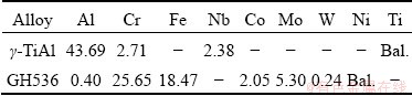
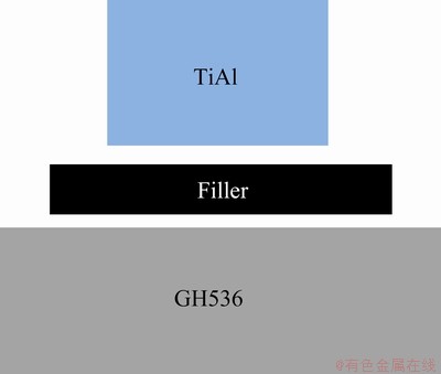
Fig. 1 Schematic diagram of assembling brazing parts
3 Results and discussion
3.1 Microstructure of Ti-Zr-Cu-Ni-Fe-Co-Mo filler alloy
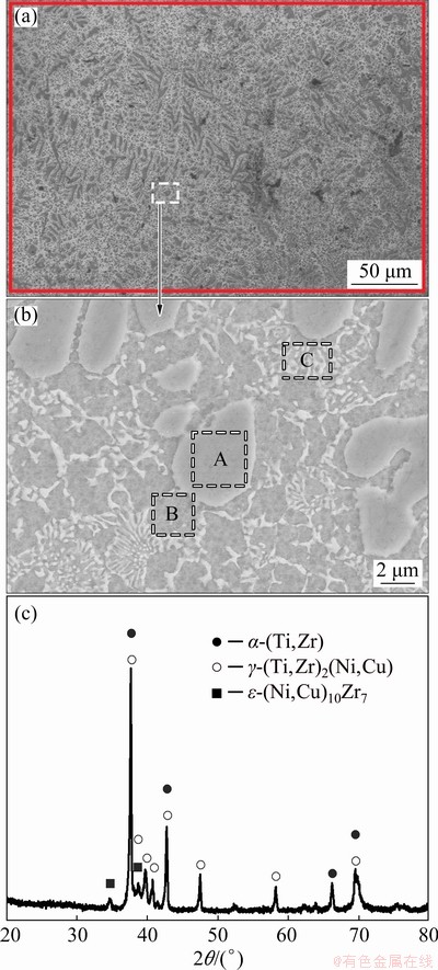
Fig. 2 Backscattered electron images (BEIs) (a, b) and XRD pattern (c) of Ti-Zr-Cu-Ni-Fe-Co-Mo crystalline filler
Figures 2(a, b) present the backscattered electron images (BEIs) of the crystalline Ti-Zr- Cu-Ni-Fe-Co-Mo filler alloy. The EDS result of the rectangular zone in Fig. 2(a) shows that the chemical composition is Ti-15.98Zr-5.82Cu- 9.35Ni-1.72Fe-2.75Co-0.23Mo (at.%), which is almost the same as the design composition of the filler alloy. This indicates that the metallurgical melting of the filler alloy is quite successful. Molybdenum equivalent [Mo]EQ is often used to classify titanium alloy on the basis of its composition and it is determined by the following equation [22,23]:
[Mo]EQ=[Mo]+[Cu]/1.3+[Ni]/0.9+[Fe]/0.35+[Co]/0.7 (1)
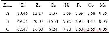
Calculated result shows that the [Mo]EQ of the crystalline filler alloy is approximate 23.94, demonstrating that the crystalline filler belongs to metastable ��-Ti alloy. According to the contrast difference in Fig. 2(b), the crystalline filler mainly consists of light gray blocky phase (marked by A), dark gray phase (marked by B) and white lamellar phase (marked by C). The EDS results of these phases are listed in Table 2. Zr is Ti neutral element characterized by chemical compatibility, and Zr is completely dissolved with Ti. Both of Cu and Ni as well as Co and Fe are ��-Ti eutectoid elements and they have similar atomic size and crystal structure. They can form an isomorphologic solid solution with each other [22,24,25]. Mo is the isomorphous element and moderate solid solution strengthener of ��-Ti, and it has high solubility in Ti [22]. Moreover, the total contents of Fe, Co and Mo are much less than those of Cu and Ni in the crystalline filler alloy, and especially the content of Mo is too little to be tested. Accordingly, both of Zr and Mo and both of Fe and Co, in a certain sense, are regarded as Ti and Ni/Cu, respectively. According to Ti-Ni (Cu, Co, Fe) binary alloy phase diagram [18], the maximum solubilities of Ni, Cu, Co and Fe are 10, 13.5, 14.5 and 22 at.%, respectively. By combining the EDS results of selected locations, our previous research [20] and Ti-Cu-Ni ternary alloy phase diagram [26] after comparison of the contents of Ni, Cu, Co and Fe in Zones A, B and C with their maximum solubilities in ��-Ti, it is concluded that the crystalline filler has a three-mixed micro- structure, i.e., the ��-(Ti,Zr) phase with Cu and Ni (marked as A), the ��-(Ti,Zr)2(Cu,Ni) with ��-(Ti,Zr) phase (marked as B) and the ��-(Ti,Zr) phase with ��-(Ti,Zr)2(Cu,Ni) (marked as C). This is further certified by the XRD pattern analysis (as shown in Fig. 2(c)).
Table 2 EDS results of each zone in Fig. 2(b) (at.%)
As shown in Fig. 3(a), the SEM image of the filler foil reveals a featureless contrast, indicating that the element distribution and microstructure of the filler foil are uniform. This is further confirmed by the EDS analysis of three random zones (marked by A, B and C, respectively), as given in Table 3. The Ti-Zr-Cu-Ni-Fe-Co-Mo filler foil is detected using X-ray diffraction, and the result shows that the pattern is only composed of a broad diffraction peak at 2�� of about 40�� (Fig. 3(b)), indicating that the filler foil is in the amorphous state. In addition, no obvious contrast is revealed in the bright-field TEM image of Fig. 3(c), and the inserted selected-area electron diffraction (SAED) pattern consists of only a diffusive halo ring, further demonstrating the amorphous nature of the filler foil.
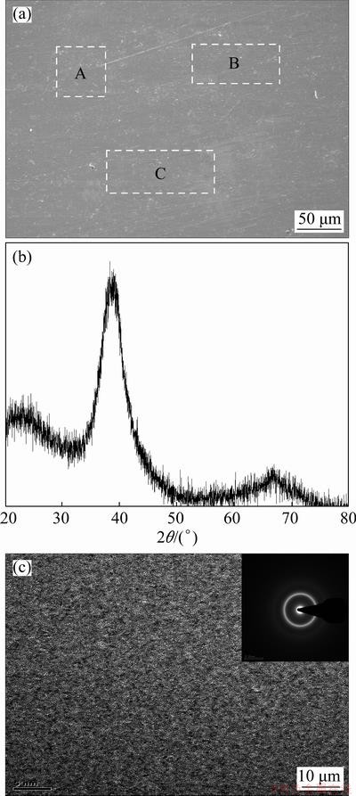
Fig. 3 Microstructure (a), XRD pattern (b) and bright- field TEM image inserted with corresponding SAED pattern (c) of Ti-Zr-Cu-Ni-Fe-Co-Mo filler foil
Table 3 EDS results of each zone in Fig. 3(a) (at.%)
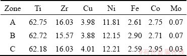
Figure 4 shows the DSC curves of amorphous and crystalline Ti-Zr-Cu-Ni-Fe-Co-Mo fillers. The melting range of the amorphous filler varies from 1039.2 to 1046.7 ��C and that of the crystalline filler varies from 1039.2 to 1065.4 ��C. Apparently, the melting temperature interval between solidus temperature (Ts) and liquidus temperature (Tl) of the amorphous filler is narrower than that of the crystalline filler, which is beneficial to reducing the void or crack formation in the brazed joint. Moreover, the liquidus temperature of the amorphous filler is lower compared with the crystalline filler, demonstrating lower brazing temperature to be employed for the amorphous filler. The lower brazing temperature can decrease the effects on microstructure and properties of parent metal and can reduce residual stress produced in the joint, which can enhance the joint strength.
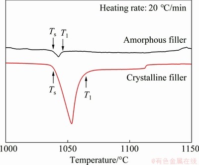
Fig. 4 DSC curves of amorphous and crystalline Ti-Zr- Cu-Ni-Fe-Co-Mo fillers
LIU et al [27] proved that the amorphous filler possessed better wettability, spreadability and adhesiveness compared with the crystalline filler. And they also pointed out that the amorphous filler contained a supercooled liquid region in an unstable state, which was inclined to accelerate the atomic diffusivity and interfacial reaction. This is favorable to obtain a sound brazed joint. Accordingly, in the following study, the amorphous Ti-Zr-Cu-Ni- Fe-Co-Mo filler is used to braze the ��-TiAl alloy and GH536. DONG et al [28] pointed out that the brazing temperature was generally at least 30 ��C above the liquidus temperature to ensure that the filler alloy was entirely melted during brazing. Therefore, the brazing temperatures ranging from 1090 to 1170 ��C are selected in this study.
3.2 Typical interfacial microstructure of ��-TiAl/ GH536 brazed joint
Figure 5 presents the BEIs of ��-TiAl/GH536 joint brazed at 1150 ��C for 10 min. As shown in Fig. 5(a), it can be clearly seen that the interfacial microstructure of the brazed joint can be divided into four reaction layers (marked by I, II, III and IV, respectively) based on the microstructural morphology. No defects such as pores or cracks are observed in the brazed joint, demonstrating that excellent metallurgical bonding occurs between the ��-TiAl/GH536 parent metal and the Ti-Zr-Cu-Ni- Fe-Co-Mo filler foil during brazing. Figure 5(b) presents the chemical composition profiles (Al, Cr, Fe, Ni and Zr) measured by EDS across the brazed joint along the bold black base line (as shown in Fig. 5(a)). It can be seen that the diffused depth of Ni atoms into the TiAl-side is significantly more than that of Zr atoms, which may be attributed to the better affinity of Ni with TiAl alloy than Zr. The similar phenomenon was also found in Ref. [28]. Meanwhile, the distributions of Cr and Fe in the brazed seam are similar, and they are mainly distributed in the Region IV. Furthermore, according to Figs. 5(a) and (b), it can be inferred that the thickness of reaction Layers I, II, III and IV are about 18, 6.8, 10.6 and 80 ��m, respectively. Accordingly, the total width of the brazed seam is about 115.4 ��m and it is about 1.9 times as the original thickness of the Ti-Zr-Cu-Ni-Fe-Co-Mo filler foil, which may be ascribed to the dissolution of the two substrates into the molten filler and increases the width of molten pool, thereby increasing the brazed seam thickness.
To verify the phase constitution in each reaction layer, we analyze the EDS results (listed in Table 4) of each spot on the basis of the contrast difference in the brazed joint. The details are as follows.
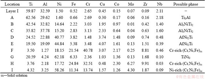
Layer I is solid-state diffusion layer of the TiAl substrate, and it is mainly composed of gray coarse acicular phase (marked by A in Fig. 5(c)) except for a little bright phase (marked by B in Fig. 5(c)), and the corresponding EDS results are listed in Table 4. Generally, the sufficient inward diffusion of filler elements into the parent alloy might lead to a change in the microstructure morphology and a decrease in melting temperature of the parent alloy [29]. Therefore, different microstructure morphologies between the matrix of reaction Layer I and the original TiAl parent alloy may result from the sufficient inward diffusion of filler elements into TiAl alloy. By combining Ti-Al binary alloy phase diagram [18] and Refs. [30-33], it is deduced that the gray coarse acicular phase A and the bright phase B are Ti3Al and Al3NiTi2, respectively. ZENG et al [34] pointed out that the Al3NiTi2 phase exhibited the structure of MgZn2 and its chemical composition ranged between Al30Ni28Ti42 (at.%) and Al50Ni16Ti34 (at.%). SCHUSTER et al [31] proposed that the Al3NiTi2 phase coexisted with liquid phase of Ti-Ni-Al above 969 ��C and precipitated during the cooling period. Therefore, the bright phase B can be considered as the Al3NiTi2 phase. Accordingly, Ti3Al is the main constitute of the reaction Layer I, which is further confirmed by the EDS result of the reaction Layer I (listed in Table 4).
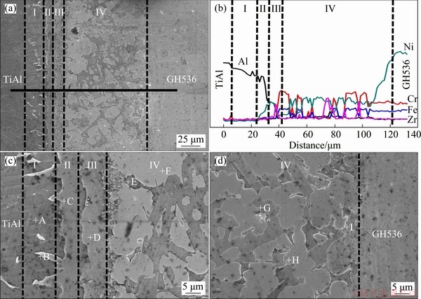
Fig. 5 Integral interfacial microstructure (a) and EDS line scanning of Al, Cr, Fe, Zr and Ni (b) of ��-TiAl/GH536 joint brazed at 1150 ��C for 10 min; high magnification BEIs of interface at TiAl-side (c) and interface at GH536-side (d)
Table 4 EDS results of each spot and Layer I in Fig. 5 (at.%)
Layer II is an isothermal solidification layer at TiAl-side. The successive inward diffusion of filler elements into TiAl alloy increases with increasing the temperature, and the concentration of filler elements decreases from the interface between filler alloy and TiAl alloy to the inner. When the temperature is up to the liquidus temperature of the filler or above, the high concentration zone of filler elements attains the appropriate solubility, and meanwhile, the TiAl substrate dissolves into the molten filler alloy. Generally, the dissolution of TiAl substrate into the molten filler alloy increases with increasing brazing temperature. The first part of the dissolution of TiAl substrate will cause the melting temperature of the molten filler to increase up to the brazing temperature, resulting in isothermal solidification occurring and the formation of isothermal solidification reaction Layer II. The second part of the dissolution of TiAl substrate will continue to diffuse in the molten filler and form mushy solidification layer with the molten filler alloy, as shown in the reaction Layer III of Fig. 5(c). The remaining part will further diffuse in molten filler alloy and generate sufficient metallurgical reaction. The main constitutions of the reaction Layers II and III are the gray phase C and the gray phase D, respectively. Based on Ti-Ni-Al ternary alloy phase diagram [26], Refs. [31-33] and the EDS analysis, it is deduced that the reaction Layer II is mainly composed of Al3NiTi2 and AlNi2Ti dominates in the reaction Layer III.
Layer IV is the widest in the brazed seam with thickness of ~80 ��m. In fact, the reaction Layer IV should include solid-state diffusion layer of the GH536 substrate, isothermal solidification layer and mushy solidification layer at GH536-side, and the residual filler layer (also named cooling solidification layer). However, the interdiffusion and metallurgical reaction between the filler alloy and GH536 parent alloy as well as Al element coming from TiAl parent alloy are so sufficient that the boundary among these layers is undistinguishable. As can be seen from Figs. 5(c, d), the reaction Layer IV mainly consists of five phases (marked by E, F, G, H and I). The Zr element mainly exists and enriches in Zones F and H, leading to higher atomic number and brighter contrast in the two zones. By combining the EDS results and Refs. [11,14,35], the zones marked by F and H can be deduced to be Cr-rich (Cr,Fe,Ni)ss. The other zones marked by E, G and I are AlNi2Ti, TiNi3 and Ni-rich (Ni,Cr,Fe)ss, respectively.
3.3 Effects of brazing temperature and brazing time on microstructure of ��-TiAl/GH536 brazed joints
Figure 6 presents the BEIs of ��-TiAl/GH536 joints brazed at different brazing temperatures for 10 min. All the brazed joints mainly include four reaction layers regardless of the brazing temperature. The thickness of brazed seam increases firstly and then decreases with increasing the brazing temperature. When the brazing temperature is lower (1090 ��C), the thickness of the brazed seam is only about 68.8 ��m, which is slightly larger than that of the original filler foil. The main reason may be related to less dissolution of parent metal into the molten filler alloy pool at lower temperature. The dissolution of parent metal into the molten filler alloy pool and the diffused depth of filler alloy atoms into the substrate increase with increasing the brazing temperature, resulting in the increasing of the brazed seam thickness, as shown in Figs. 6(b-d). Moreover, the flowability of the filler alloy is extremely excellent at high temperature and the molten filler is easily lost from the gap between the two base metals. Therefore, the thickness of the brazed seam decreases when the brazing temperature is further increased to 1150 and 1160 ��C, as shown in Figs. 5(a) and 6(e), and the corresponding thicknesses of the brazed seam are about 115.4 and 111.7 ��m, respectively. The maximum thickness of the brazed seam is about 136.2 ��m obtained at 1140 ��C.
It is worth noting that distinct microcracks on the side of TiAl alloy can be observed when the brazing temperature is 1090 ��C, and they mainly exist in the reaction Layer II, as shown in Fig. 6(a). By the EDS results listed in Table 5, overmuch brittle phase Al3NiTi2 exists in the reaction Layer II, which leads to internal stress concentration and the formation of microcracks during cooling process. The microcrack gradually decreases with increasing brazing temperature, and completely disappears at 1130 ��C, as shown in Fig. 6(c). No microcracks can be found in the brazed seam when the brazing temperature is 1140 and 1150 ��C, as shown in Figs. 6(d) and 5(a), respectively, which is beneficial to obtaining a sound brazed joint and improving the shear strength.
It is indicated that the brittle Al3NiTi2 intermetallic is the main controlling factor of crack generation. Generally, the presence of cracks deteriorates the shear strength of brazed joint. LEE and WU [36] pointed out that ��2-Ti3Al was stable at 1150 ��C. They also stated that once the continuous��2-Ti3Al fully formed in the brazed seam, the further atomic interdiffusion between TiAl parent alloy and filler alloy would be obstructed. Therefore, the reaction Layer I with continuous ��2-Ti3Al can be considered as a diffusion barrier for TiAl parent alloy atoms and filler alloy atoms. At lower brazing temperature (1090 and 1110 ��C), the element Al mainly enriches in the reaction Layers I and II, leading to the existence of overmuch brittle Al3NiTi2 intermetallics in the reaction Layer II, and thereby the microcrack formation. With increasing of the brazing temperature, the atomic inter- diffusion in the reaction Layers II, III and IV is accelerated, which makes metallurgical reaction more sufficient and decreases the contents of element Al and brittle Al3NiTi2 intermetallics in the reaction Layer II. Therefore, the cracks disappear when the brazing temperature is increased up to 1130 ��C. With further increasing of the brazing temperature, the adequate atomic interdiffusion and metallurgical reaction between the GH536 parent alloy and the filler alloy occur, and the Cr-rich (Cr,Ni,Fe)ss and TiNi3 phases in the reaction Layer IV are gradually refined and distribute evenly, as shown in Fig. 5(a) and Figs. 6(c, d), which will be beneficial to improving the joint strength. Nevertheless, when the brazing temperature exceeds 1150 ��C, the ��2-Ti3Al becomes unstable and the equilibrium of ��2-Ti3Al barrier layer is broken. Also, the atomic interdiffusion between TiAl parent alloy and filler alloy, and especially, the dissolution of TiAl parent alloy, increases sharply. Moreover, the residual stress in the brazed joint increases with increasing the brazing temperature due to different thermal expansion coefficients in each reaction layer. Accordingly, at the brazing temperature of 1170 ��C, overmuch Al3NiTi2 intermetallics form and micro-cracks occur in the reaction Layer II again, as shown in Fig. 6(f). Therefore, 1150 ��C is selected as brazing temperature to study the influence of brazing time on ��-TiAl/GH536 brazed joints.
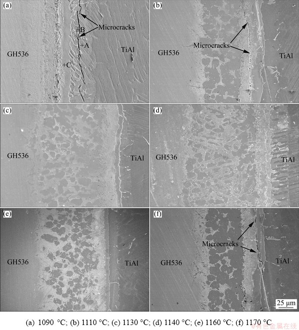
Fig. 6 Interfacial microstructures of ��-TiAl/GH536 joints brazed at different temperatures for 10 min
Table 5 EDS results of each spot in Fig. 6(a) (at.%)
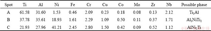
Figure 7 shows the BEIs of ��-TiAl/GH536 joints brazed at 1150 ��C for different time. The total thickness of brazed seam remains basically unchanged regardless of brazing time, but some obvious change occurs in the microstructure (e.g. the TiNi3 phase) of the reaction Layer IV with the variation of the brazing time. It is well known that the diffusion of the filler element especial Cu and Ni into TiAl alloy noticeably depends on their concentration gradients during brazing. At early stage (e.g. brazing time of 0 min), large amounts of Ni elements are enriched in the molten filler alloy due to the abrupt dissolution of the GH536 parent alloy. Meanwhile, only few Ni and Cu diffuse from the filler alloy into TiAl alloy and then solidification occurs quickly, resulting in the formation of massive bulky TiNi3 intermetallics in the reaction Layer IV. With increasing of the brazing time, more diffusion of Ni and Cu into the TiAl alloy and sufficient atomic interdiffusion and metallurgy reaction lead to dispersed distribution of brittle intermetallic TiNi3. Generally, low content of intermetallic compound precipitating in the brazed seam can act as second-phase particles and has dispersion strengthening effect, which is beneficial to improving the joint strength [25]. When the brazing time is up to 10 min, intermetallic TiNi3 sufficiently precipitates in the brazed seam, as shown in Fig. 5(a), resulting in obtaining the maximum joint strength. The corresponding filler element (mainly Ni and Cu) concentration should be up to the limit of solubility. As the brazing time is further prolonged to 15 and 20 min, more and more Ni elements continuously diffuse into the molten filler metal, and more TiNi3 intermetallics form and break the local equilibrium between the TiNi3 intermetallics and the solid-solution phases, resulting in the deterioration of the joint strength. Moreover, inconspicuous microcracks can be observed in the reaction Layer II, as shown in Fig. 7(d), which may be attributed to excess residual thermal stress resulted from the long thermal cycle or the content increase of TiNi3 intermetallics with increasing the brazing time.
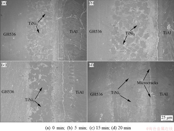
Fig. 7 Microstructures of ��-TiAl/GH536 joints brazed at 1150 ��C for different brazing time
3.4 Shear strength and fracture mechanism of ��-TiAl/GH536 brazed joints
Figure 8 shows the average shear strength of TiAl/GH536 joints brazed with different brazing parameters. The shear strength of the brazed joint increases firstly and then decreases with the brazing temperature or brazing time. It is clearly seen that the maximum shear strength of the brazed joint is 262 MPa obtained at 1150 ��C for 10 min, and variation in shear strength with the brazing parameters depends noticeably on the interfacial microstructure of the brazed joint. At lower brazing temperature (1090 and 1110 ��C), the brazed joints with microcracks existing in the reaction Layer II exhibit much lower shear strength compared with the brazed joints without microcracks (as shown in Fig. 8(a)), and the corresponding shear strengths are only 20 and 62 MPa, respectively. When the brazing time is short (0 min) at 1150 ��C, the shear strength is only 181 MPa. The likely reason is the insufficient metallurgical reaction in the brazed seam, which results from the low atomic diffusion and the insufficient dissolution reaction between the parent alloy and Ti-Zr-Cu-Ni-Fe-Co-Mo filler alloy at lower brazing temperature or shorter brazing time. And the insufficient metallurgical reaction may make much more Al elements from the dissolution of TiAl substrate enrich and overmuch brittle phase Al3NiTi2 generates in Layer II, resulting in the stress concentration and the formation of microcracks, which can weaken the joint. Generally, increasing brazing temperature or prolonging brazing time can enhance metallurgical reaction, thereby improving the shear strength of the brazed joint. Once the brazing temperature is increased up to 1160 ��C, Cr-rich (Cr,Fe,Ni)ss and TiNi3 become coarse, and the morphology of the reaction Layer IV changes obviously. Especially, the microcracks are found again in the reaction Layer II of the joint brazed at 1170 ��C, due to the formation of massive Al3NiTi2 intermetallics and residual stress. According to Ti-Ni-Al ternary alloy diagram [30] and works of SIMOES et al [37] and REN et al [14], Al3NiTi2 and TiNiAl intermetallics exhibit the similar structures and the hardness of AlNiTi is about 17.2 GPa, which is higher than that of AlNi2Ti, TiNi3, TiAl and Ti3Al intermetallics as well as TiAl and GH536 substrate. Generally, the harder the successive intermetallics layer is, the lower the bonding strength is obtained [38]. Accordingly, the shear strength of the brazed joint turns to decrease sharply with further increasing of the brazing temperature and is only 80 MPa at 1170 ��C. And nucleation and propagation of cracks prefer to occur in the Layer II mainly consisting of brittle Al3NiTi2, which is proven by the fracture behavior, as shown in Fig. 9. When the brazing time exceeds 10 min at 1150 ��C, the formation of excessive intermetallic compound TiNi3 decreases the shear strength, as shown in Fig. 8(b). So, the cracks and overmuch intermetallic compounds in the brazed seam should be avoided to obtain robust joint. It is notable that the variation of joint strength as a function of brazing temperature is more obvious than that of brazing time.
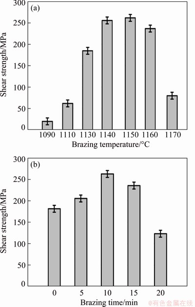
Fig. 8 Shear strength of ��-TiAl/GH536 joints brazed at different brazing temperatures for 10 min (a) and at 1150 ��C for different brazing time (b)
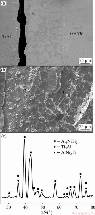
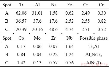
Fig. 9 Shear fracture path (a) and fracture morphology (b) of joint brazed at 1150 ��C for 10 min; XRD pattern of fracture surface after shear test (c)
The shear fracture should mainly occur in the reaction Layer II of the joints brazed at 1090, 1110 and 1170 ��C for 10 min due to the existence of cracks and overmuch brittle Al3NiTi2. According to aforementioned analysis, although the interfacial morphologies and phase compositions in each reaction layer of the joints brazed with other brazing parameters are almost similar, the maximum shear strength of the brazed joint is obtained at 1150 ��C for 10 min. Therefore, the shear fracture path and fracture morphology of ��-TiAl/ GH536 joint brazed at 1150 ��C for 10 min are selected typically, as shown in Figs. 9(a, b). It is obviously seen that the fracture surface exhibits typical cleavage fracture characteristics and the fracture mainly propagates in the reaction Layer II. The EDS results (Table 6) indicate that the brittle Al3NiTi2 intermetallics occupy most of the fracture surface, which is further confirmed by the XRD analysis of the fracture surface (as shown in Fig. 9(c)). Accordingly, it is inferred that the reaction Layer II primarily consisting of brittle Al3NiTi2 intermetallics is the weakest zone in the brazed seam.
Table 6 EDS results of each spot in Fig. 9(b) (at.%)
4 Conclusions
(1) The typical interfacial microstructure of ��-TiAl/GH536 joint brazed at 1150 ��C for 10 min is ��-TiAl/Ti3Al/Al3NiTi2/AlNi2Ti/Cr-rich (Cr,Ni,Fe)ss+ AlNi2Ti + Ni-rich (Ni,Cr,Fe)ss + TiNi3/GH536. Obvious microcracks mainly distribute in the reaction Layer II in the joint brazed at 1090, 1110 and 1170 ��C for 10 min, which result from the massive brittle Al3NiTi2 intermetallics.
(2) At a brazing time of 10 min, the average shear strength of the joint increases with brazing temperature from 1090 to 1150 ��C and then decreases from 1160 to 1170 ��C, which is consistent with the variation of the total thickness of the brazed seam. Meanwhile, the total thickness of brazed seam basically remains unchanged regardless of brazing time at 1150 ��C. The average shear strength increases firstly with the brazing time from 0 to 10 min and then decreases from 15 to 20 min, which noticeably depends on the microstructure and distribution of the TiNi3 in the reaction Layer IV. The maximum shear strength of 262 MPa is obtained at 1150 ��C for 10 min. In addition, the variation of joint strength as a function of brazing temperature is dramatic compared with the brazing time.
(3) The fracture surface exhibits typical cleavage fracture characteristics and the cracks mainly generate in the reaction Layer II and then gradually propagate to the reaction Layers I and III. The reaction Layer II is the weakest zone in the brazed seam and the brittle Al3NiTi2 intermetallics occupy most of the fracture surface.
References
[1] GAO Shuang, HOU Jie-shan, GUO Yong-an, ZHOU Lan-zhang. Phase precipitation behavior and tensile properties of as-cast Ni-based superalloy during heat treatment [J]. Transactions of Nonferrous Metals Society of China, 2018, 28: 1735-1744.
[2] PERRUT M, CARON P, THOMAS M, COURET A. High temperature materials for aerospace applications: Ni-based superalloys and ��-TiAl alloys [J]. Compets Rendus Physique, 2018, 19: 657-671.
[3] XU Zhen-zhen, DONG Zhi-qiang, YU Zhao-hui, WANG Wen-ke, ZHANG Jian-xun. Relationships between microhardness, microstructure, and grain orientation in laser-welded joints with different welding speeds for Ti6Al4V titanium alloy [J]. Transactions of Nonferrous Metals Society of China, 2020, 30: 1277-1278.
[4] KOKABI D, KAFLOU A, GHOLAMIPOUR R, POURANVARI M. Microstructural evaluation during dissimilar transient liquid phase bonding of TiAl/Ni-based superalloy [J]. Journal of Alloys and Compounds, 2020, 825: 153999.
[5] LI Li, LI Xiao-qiang, HU Ke, HE Bo-lin, MAN Hua. Brazeability evaluation of Ti-Zr-Cu-Ni-Co-Mo filler for vacuum brazing TiAl-based alloy [J]. Transactions of Nonferrous Metals Society of China, 2019, 29: 754-763.
[6] LUO G X, WU G Q, HUANG Z, RUAN Z J. Diffusion bonding of laser-surface-modified gamma titanium aluminide alloy to nickel-based casting alloy [J]. Scripta Materialia, 2007, 57: 521-524.
[7] HE Peng, WANG Jun, LIN Tie-Song, LI Hai-xin. Effect of hydrogen on diffusion bonding of TiAl-based intermetallics and Ni-based superalloy using hydrogenated Ti6Al4V interlayer [J]. International Journal Hydrogen Energy, 2014, 39: 1882-1887.
[8] LI Z F, WU G Q, HUANG Z, RUAN Z J. Diffusion bonding of laser surface modified TiAl alloy/Ni alloy [J]. Materials Letters, 2004, 58: 3470-3473.
[9] DONG K W, KONG J, WEI Z X, YANG Y, LIANG Y L, PENG Y, ZHOU Q, WANG K H. Thermoplastic bonding (TPB) of TiAl- and Ni-based alloys with Zr-Al-Ni-Cu bulk metallic glass [J]. Materials Design, 2019, 181: 107936.
[10] CAI Xiao-long, SUN Da-qian, LI Hong-mei, MENG Chao, WANG Lin, SHEN Cheng-jie. Dissimilar joining of TiAl alloy and Ni-based superalloy by laser welding technology using V/Cu composite interlayer [J]. Optics and Laser Technology, 2019, 111: 205-213.
[11] LI Hai-xin, WEI Hong-mei, HE Peng, LIN Tie-song, FENG Ji-cai, HUANG Yu-dong. Effects of alloying elements in GH99 superalloy on microstructure evolution of reactive brazing TiAl/GH99 joints [J]. Intermetallics, 2013, 34: 69-74.
[12] TETSUI T. Effects of brazing filler on properties of brazed joints between TiAl and metallic materials [J]. Intermetallics, 2001, 9: 253-260.
[13] SIMOES S, TAVARES C J, GUEDES A. Joining of ��-TiAl alloy to Ni-based superalloy using Ag-Cu sputtered coated Ti brazing filler foil [J]. Metals, 2018, 8(9): 723.
[14] REN H S, XIONG H P, LONG W M, SHEN Y X, PANG S J, CHEN B, CHENG Y Y. Interfacial diffusion reactions and mechanical properties of Ti3Al/Ni-based superalloy joints brazed with AgCuPd filler metal [J]. Materials Characterization, 2018, 144: 316-324.
[15] DONG Kei-wei, KONG Jian. A high-strength vacuum- brazed TiAl/Ni joint at room temperature and high temperature with an amorphous foil Zr-Al-Ni-Co filler metal [J]. Journal of Manufacturing Processes, 2019, 44: 389-396.
[16] SHI J M, ZHANG L X, TIAN X Y, LI H W, FENG J C. Vacuum brazing of the Cf/C composite and Ni base superalloy using MBF 20 filler [J]. Vacuum, 2018, 156: 427-433.
[17] YE L, XIONG H P, HUAI J F, CHEN B. Microstructures of the TiAl joints brazed with Ti-Zr-based filler metals [J]. Weld World, 2015, 59: 201-208.
[18] MASSALAKI T B, OKAMOTO H, SUBRAMANIAN P R, KACPRZAK L. Binary alloy phase diagrams [M]. 2nd ed. Ohio: ASM International, 1990.
[19] SUN Lu-lu, PANG Shu-jie, LIU Ying, XIONG Hua-ping, ZHANG Tao. A Ti-Zr-Cu-Ni-Co-Fe-Al-Sn amorphous filler metal for improving the strength of Ti-6Al-4V alloy brazing joint [J]. Progress in Natural Science: Materials International, 2017, 27: 687-694.
[20] LI Li, LI Xiao-qiang, HU Ke, QU Sheng-guan, YANG Chao, LI Zhi-feng. Effects of brazing temperature and testing temperature on the microstructure and shear strength of ��-TiAl joints [J]. Materials Science & Engineering A, 2015, 634: 91-98.
[21] YANG Zhen-wen, LIN Jia-mei, WANG Ying, WANG Dong-po. Characterization of microstructure and mechanical properties of Al2O3/TiAl joints vacuum-brazed with Ag-Cu-Ti + W composite filler [J]. Vacuum, 2017, 43: 294-302.
[22] LEYENS C, PRTER S. Titanium and titanium alloys [M]. Weinheim: Wiley-VCH GmbH & Co KGaA, 2003.
[23] HSIEH C T, CHU C Y, SHIUE R K, TSAY L W. The effect of post-weld heat treatment on the notched tensile fracture of Ti-6Al-4V to Ti-6Al-6V-2Sn dissimilar laser welds [J]. Materials and Design, 2014, 59: 227-232.
[24] CAI Y S, LIU R C, ZHU Z W, CUI Y Y, YANG R. Effect of brazing temperature and brazing time on the microstructure and tensile strength of TiAl-based alloy joints with Ti-Zr-Cu-Ni amorphous alloy as filler metal [J]. Intermetallics, 2017, 91: 35-44.
[25] PANG Shu-jie, SUN Lu-lu, XIONG Hua-ping, CHEN Chen, LIU Ying, LI Hai-fei, ZHANG Tao. A multicomponent TiZr-based amorphous brazing filler metal for high-strength joining of titanium alloy [J]. Scripta Materialia, 2016, 117: 55-59.
[26] VILLARS P, PRINCE A, OKAMOTO H. Handbook of ternary alloy phase diagrams [M]. Ohio: ASM International, 1997.
[27] LIU Y H, HU J D, SHEN P, HAN H X, LI J C. Microstructure and mechanical properties of jointed ZrO2/Ti-6Al-4V alloy using Ti33Zr17Cu50 amorphous brazing filler [J]. Materials Design, 2013, 47: 281-286.
[28] DONG Hong-gang, YANG Zhong-lin, YANG Guo-shun, DONG Chuang. Vacuum brazing of TiAl alloy to 40Cr steel with Ti60Ni22Cu10Zr8 alloy foil as filler metal [J]. Materials Science & Engineering A, 2013, 561: 252-258.
[29] SEKULIC D P. Advances in brazing-Science, technology and applications [M]. Philadelphia: Woodhead Publishing Limited, 2013.
[30] JUNG In-soo, KIM Min-chul, LEE Je-hyun, OH Myung-hoon, WEE Dang-moon. High temperature phase equilibria near Ti-50at.%Al composition in Ti-Al system studied by directional solidification [J]. Intermetallics, 1999, 7: 1247-1253.
[31] SCHUSTER J C, PAN Z, LIU S H, WEIZER F, DU Y. On the constitution of the ternary system Al-Ni-Ti [J]. Intermetallics, 2007, 15: 1257-1267.
[32] RAGHAVAN V. Al-Ni-Ti (aluminum-nickel-titanium) [J]. Journal of Phase Equilibria and Diffusion, 2005, 26: 268-272.
[33] WIERZBA B. Phase competition in ternary Ti-Ni-Al system [J]. Physica A, 2016, 454: 110-116.
[34] ZENG K, SCHMID-FETZER R, HUNEAU B, ROGL P, BAUER J. The ternary system Al-Ni-Ti. Part II: Thermodynamic assessment and experimental investigation of polythermal phase equilibria [J]. Intermetallics, 1999, 7: 1347-1359.
[35] YANG Z W, LIAN J, CAI X Q, WANG Y, WANG D P, LIU Y C. Microstructure and mechanical properties of Ni3Al- based alloy joint transient liquid phase bonded using Ni/Ti interlayer [J]. Intermetallics, 2019, 109: 179-188.
[36] LEE S J, WU S K. Infrared joining strength and interfacial microstructures of Ti-48Al-2Nb-2Cr intermetallics using Ti-15Cu-15Ni foil [J]. Intermetallics, 1999, 7: 11-21.
[37] SIMOES S, VIANA F, KOCAK M, RAMOS A S, VIEIRA M T, VIEIRA M F. Diffusion bonding of TiAl using reactive Ni/Al nanolayers and Ti and Ni foils [J]. Materials Chemistry and Physics, 2011, 128: 202-207.
[38] REN H S, XIONG H P, LONG W M, CHEN B, SHEN Y X, PANG S J. Microstructures and mechanical properties of Ti3Al/Ni-based superalloy joints brazed with AuNi filler metal [J]. Journal of Materials Science & Technology, 2019, 35: 2070-2078.
Ti-Zr-Cu-Ni-Fe-Co-Moǥ�ϺϽ�ǥ����-TiAl/GH536��ͷ������֯�����ǿ��
�� ��1,2���� Ρ1����־ѩ1���� ��3����Сǿ2
1. ������ͨ��ѧ ���Ͽ�ѧ�빤��ѧԺ���ϲ� 330013��
2. ����������ѧ ���ҽ������Ͻ������ι��̼����о����ģ����� 510640��
3. �г��Ͼ�����������˾ ת�����Ʋ����Ͼ� 210031
ժ Ҫ������Ti-Zr-Cu-Ni-Fe-Co-Mo��Ϊǥ�ϣ���ǥ���¶�1090~1170 ��C��ǥ��ʱ��0~20 min�Ĺ��ղ����£�ʵ�֦�-TiAl��GH536�Ͻ��ǥ�����ӣ�����SEM��EDS��XRD������������о�ǥ���¶Ⱥ�ǥ��ʱ���ǥ����ͷ����֯�ͼ���ǿ�ȵ�Ӱ�졣�����������ͬ���ղ����»�õĦ�-TiAl/GH536ǥ����ͷ������4�����淴Ӧ�㡣����ǥ���¶ȵ����ߺ�ǥ��ʱ����ӳ���ǥ����Ⱥ�ǥ����ͷ��ƽ������ǿ�Ⱦ�����������С��ǥ���¶�1150 ��C��ǥ��ʱ��10 minʱ��õ�ǥ����ͷ�ļ���ǿ�����262 MPa��Al3NiTi2��TiNi3���Խ����仯�����Dz������ƺͽ��ͽ�ͷǿ�ȵ��������أ�Al3NiTi2���Խ����仯���X��ռ�������ʵ��ͽ������������ļ��жϿڱ��档
�ؼ��ʣ���-TiAl�Ͻ��������ºϽ����ǥ�����Ǿ�ǥ�ϣ�����֯������ǿ��
(Edited by Bing YANG)
Foundation item: Project (51865012) supported by the National Natural Science Foundation of China; Project (20202BABL204040) supported by the Natural Science Foundation of Jiangxi Province, China; Project (2016005) supported by the Open Foundation of National Engineering Research Center of Near-net-shape Forming for Metallic Materials, China; Project (GJJ170372) supported by the Science Foundation of Educational Department of Jiangxi Province, China; Project (JCKY2016603C003) supported by the GF Basic Research Project, China; Project (JPPT125GH038) supported by the Research Project of Special Furnishment and Part, China
Corresponding author: Xiao-qiang LI; Tel/Fax: +86-20-87111080; E-mail: lixq@scut.edu.cn
DOI: 10.1016/S1003-6326(20)65367-5
Abstract: The influence of brazing temperature and brazing time on the microstructure and shear strength of ��-TiAl/GH536 joints brazed with Ti-Zr-Cu-Ni-Fe-Co-Mo filler was investigated using SEM, EDS, XRD and universal testing machine. Results show that all the brazed joints mainly consist of four reaction layers regardless of the brazing temperature and brazing time. The thickness of the brazed seam and the average shear strength of the joint increase firstly and then decrease with brazing temperature in the range of 1090-1170 ��C and brazing time varying from 0 to 20 min. The maximum shear strength of 262 MPa is obtained at 1150 ��C for 10 min. The brittle Al3NiTi2 and TiNi3 intermetallics are the main controlling factors for the crack generation and deterioration of joint strength. The fracture surface is characterized as typical cleavage fracture and it mainly consists of massive brittle Al3NiTi2 intermetallics.
