
Trans. Nonferrous Met. Soc. China 25(2015) 146-153
Fabrication and characterization of electrodeposited nanocrystalline Ni-Fe alloys for NiFe2O4 spinel coatings
Li MA1,2, Long ZHANG2, Xiao-bing LI1, Zhi-you LI2, Ke-chao ZHOU2
1. School of Metallurgy and Environment, Central South University, Changsha 410083, China;
2. State Key Laboratory of Powder Metallurgy, Central South University, Changsha 410083, China
Received 27 April 2013; accepted 21 November 2014
Abstract:
Nanocrystalline Ni-Fe FCC alloy coatings with Fe content of 1.3%-39% (mass fraction) were fabricated on the nickel substrates using a DC electrodeposition technique. The crystal structure, lattice strain, grain size and lattice constant of the Ni-Fe alloy coatings were studied by X-ray diffraction technique. The chemical composition and surface morphology of the FCC Ni-Fe alloy coatings were investigated with the energy dispersive X-ray spectroscopy (EDS) and atomic force microscopy (AFM). The results show that the Fe content of the Ni-Fe alloy coatings has a great influence on the preferred orientation, grain size, lattice constant and lattice strain. FCC Ni-Fe alloy coatings exhibit preferred orientations of (200) or (200)(111). With an increase of Fe content, the preferred growth orientation of (200) plane is weakened gradually, while the preferred growth orientation of (111) increases. An increase of the Fe content in the range of 1.3%-25% (mass fraction) results in a significant grain refinement of the coatings. Increasing the Fe content beyond 25% does not decrease the grain size of FCC Ni-Fe alloys further. The lattice strain increases with increasing the Fe content in the FCC Ni-Fe alloys. Since the alloys with Fe content not less than 25% has similar grain size (~11 nm), the increase in the lattice strain with the increase of Fe content cannot be attributed to the change in the grain size.
Key words:
Ni-Fe alloy; electrodeposition; nanocrystalline; NiFe2O4 spinel; coating;
1 Introduction
Ni-Fe alloy films are used in a wide variety of applications for storage, recording and memory devices for computers, magnetic actuators and magnetic shielding, because of their ability to exhibit stable, low coefficient of thermal expansion (CTE) and beneficial magnetic properties at room temperature [1,2]. Particularly, Ni-Fe alloy films from permalloy (Ni-20%Fe, mass fraction) to invar (Ni-64%Fe, mass fraction) have a wide spectrum of physical properties [3,4]{Cooke, 2003 #1921}. Permalloy films were commonly used in magnetoresistive sensors based on the intrinsic magnetoresistance of the ferromagnetic material (anisotropic magnetoresistance sensors) or on ferromagnetic/non-magnetic heterostructures (giant magnetoresistance multilayers, spin valve and tunneling magnetoresistance devices) [3]. Invar alloy films were used in the electronic, aerospace and mechanical industry, based on their low coefficient of thermal expansion [4].
Recently, Ni-Fe alloy electrodeposition followed by thermal oxidation to synthesize NiFe2O4 spinel coatings has received great attention due to low cost of this process and its capability to coat substrates with complex geometries. A spinel ferrite coating with general formula of MFe2O4, especially NiFe2O4 coating, is of increasing interest as this material finds or promises numerous applications in microwave devices [5], magnetic high-density data storage [6], solid oxide fuel cell (SOFC) [7] and inert anode materials for aluminium electrolysis [8-10].
Since the high-temperature treatment in air or oxygen-enriched atmosphere is unavoidable in spinel fabrication processes, metal or alloy oxidation will occur and result in microstructural change. The influence of such a microstructural change on the performance of spinels is by no means negligible. It has been reported that apart from oxidation temperature, many parameters, such as alloy composition, grain size, preferred orientation and lattice strain, greatly affect the growth kinetics and the oxide morphology [11-13]. For example, the nanocrystallization of Ni-based superalloys has been found to be capable of obviously enhancing their high-temperature oxidation resistance, because a refinement of the alloy grain size can promote a continuous protective Al2O3 or Cr2O3 external scale formed on the alloy surface due to the high concentration of grain boundaries which act as preferential and faster transport paths [12]. In addition, it has been found that between 873 and 1173 K, the oxide growth rate on (111) Ni face is over one order of magnitude lower than that observed for (100) Ni face [13]. The similar phenomena have also been observed in electrodeposited nanocrystalline Ni coatings with different preferred orientations in our previous studies [14].
It has recently reported that a NiO/NiFe2O4 composite coating thermally converted from an electroplated Ni-7Fe alloy exhibited increasing hot corrosion resistance under an atmosphere of Na3AlF6-AlF3-CaF molten salts and air at 960 ��C, compared with bare Ni metal, based on its dense structure, homogeneously dispersed intragranular and intergranular NiFe2O4 precipitates [13]. Therefore, the properties of NiFe2O4 coating, such as the magnetic and high-temperature corrosion resistance properties, strongly depended on the Ni-Fe alloy composition and its microstructure, such as grain size, preferred orientation and lattice strain. These parameters may be controlled by adjusting the deposition conditions such as the composition of the deposition bath. Thus, it is necessary to investigate the effects of the deposition conditions to produce optimum electrodeposits and spinel coating with uniform physical and chemical properties.
In this work, the electrodeposition method was adopted to prepare Ni-Fe coatings, and the effect of electrolyte composition on the Fe content in the alloy coating was focused on. The formation of nano-grains in the Ni�CFe coatings, and the variation of their microstructures such as grain size, preferred orientation and lattice strain with the electrolyte composition was investigated.
2 Experimental
2.1 Electrodeposition
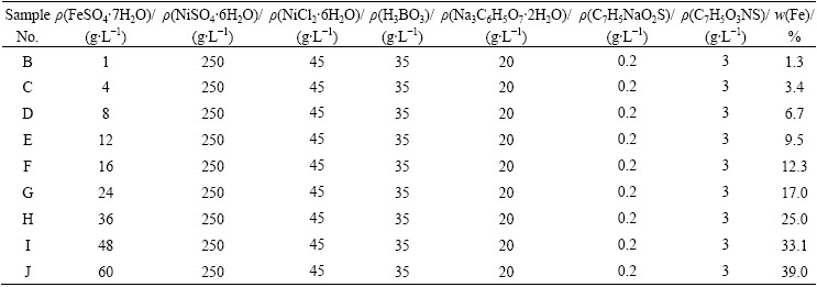
Pure nickel (99.5 %) specimens with dimensions of 30 mm��30 mm��2 mm were machined and polished using SiC paper up to 800-grit finish, and then electroplated (on all sides) with a film of Ni-(1.3%- 39%)Fe (mass fraction) from a bath containing nickel sulfamate, nickel chloride and iron sulfate. Each bath was composed of 250 g/L NiSO4��6H2O, 45 g/L NiCl2��6H2O, 35 g/L H3BO3, 20g/L sodium citrate, 0.2 g/L sodium benzenesulphinate, and 3 g/L saccharin. An appropriate mass of FeSO4��7H2O was added into each bath to satisfy the specified Ni/Fe ratio. The composition of the plating bath is shown in Table 1. The pH value of the bath was adjusted to 3.5 by H2SO4 solution. The bath temperature was kept at (55��3) ��C. The substrates were sequentially ultrasonically cleaned in ethanol, acetone, and distilled water, each for 10 min, then activated in an acidic solution (V(96% H2SO4):V(H2O))= 1:1 in volume) for 30 s, washed in distilled water, and finally immersed immediately in the plating bath for electrodeposition. The applied current (DC) density was 5 A/dm2 for all coatings. The thickness of the coatings was in the range of 160-180 ��m.
2.2 Coating characterization
X-ray diffraction (XRD, Rigaku/MAX-3A) technique with Cu Ka radiation (��=0.154 nm, scanning rate 4 (��)/min) was employed to characterize the crystal structure, lattice strain, grain size and lattice constant using the Philips APD3720. The line profile software, which accompanies the Philips system, was used for the analysis of the XRD results. Single line analysis (X-ray diffraction line broadening analysis) was employed for the calculation of the grain size and strain. The lattice parameters were measured by analyzing either the (111) or the (200) peak for the FCC Ni-Fe alloys depending on their crystal structures. The crystallite size and internal strains were estimated based on the (111) and (200) peaks of all the FCC Ni-Fe alloys. The analysis of the chemical composition was carried out on an energy dispersive X-ray spectroscopy (EDX, Oxford Link ISIS 300). The surface morphologies of the samples were investigated using the atomic force microscopy (AFM).
Table 1 Compositions of plating bath
3 Results and discussion
3.1 Composition of Ni-Fe coatings
At a fixed content of Ni2+, the dependence of the composition of Ni-Fe alloys on the Fe2+ content in the electrolyte is presented in Fig. 1. It should be noted that the accuracy of iron in nickel, which can be measured by microprobe analysis, is approximately ��0.5%. It can be seen in Fig.1 that Fe2+ content of the plating bath has a great influence on the composition of Ni-Fe alloy plating. A slight change of Fe2+ content in the bath leads to a great change of Fe content in the plating. This indicates that abnormal codeposition happened during the codeposition Ni-Fe alloy. The standard reduction potential of Ni2+ ( ) is 0.191V, which is higher than that of Fe2+ (
 ). In theory, nickel is deposited on the cathode first; however, the result showed that iron was deposited on the cathode first. It has been reported that during the codeposition process of Ni-Fe alloy, hydrogen evolution reaction occurred on the cathode surface, leading to the increase of the pH value around the cathode surface. Then, a lot of OH- ions were enriched in the cathode, reacting with the Fe2+ that spread to the cathode surface to form Fe(OH)+ and other intermediate products [15]. These intermediate products were absorbed to the cathode surface, hindering the deposition of nickel. As a result, abnormal codeposition took place [16]. Such a vast amount of hydrogen evolution occurred only when the current density was high [16]. However, abnormal codeposition also occurred during the electrodeposition of Ni-Fe alloy coating, although a low current density (J=5 A/dm2) was applied in this work. Such phenomenon cannot be explained by the above theories. Furthermore, another viewpoint was put forward by someone. On the cathode surface, the activity of Fe2+ is higher than that of Ni2+. Fe2+ was adsorbed preferentially on the cathode surface where Fe2+ discharged easily, hindering the deposition of Ni2+. As a result, it made the depositing rate of Ni2+ slow, while Fe2+ was deposited preferentially [17].
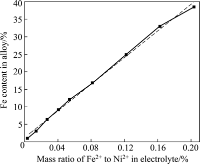
Fig. 1 Fe content in Ni-Fe alloy vs mass ratio of Fe2+ to Ni2+ in electrolyte
3.2 Structure of Ni-Fe coatings
3.2.1 XRD results
The XRD patterns of the Ni-Fe alloy coatings and the pure nickel substrate are shown in Fig. 2. Only Ni diffraction peaks appear for samples B-J, while no Fe diffraction peak could be observed. Thus, the XRD patterns confirm that the electrodeposited Ni-Fe alloy coating is composed of a solid solution. In comparison with the nickel substrate, the XRD patterns of the electrodeposited materials show changes in peak widths, peak locations and peak intensities. The relative intensities of Ni(111) and Ni(200) peaks change a lot. Preferred orientations of the coating, full width at half maximum (FWHM) of diffraction peak, lattice constant, grain size, and the change of microstress will be addressed in the following in details.
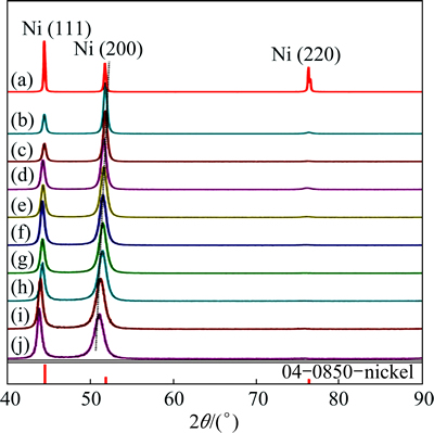
Fig. 2 XRD patterns of Ni-Fe alloy coatings with different Fe contents ((a)-(j) correspond to samples A-J, and sample A is nickel substrate)
3.2.2 Preferred orientations of coatings
It can be seen from Fig. 2 that there are considerable changes in the peak intensities of the electrodeposited materials in comparison with the nickel standard (04-0850) in PDF card in Jade 5.0. For all coatings, the (220) peak intensity is reduced very much compared with a random crystal distribution. On the other hand, the (200) peak intensity is enhanced over the random distribution, indicating the presence of a (200) texture component. However, with increasing Fe content in the coatings, the relative intensity of (200) plane decreases gradually, while the relative intensity of (111) plane increases gradually.
In order to compare the crystal preferred growth orientations of Ni-Fe alloy coatings with different Fe contents, the (111) and (200) texture coefficients (TC) of Ni-Fe alloy coatings are calculated by [18]
 (1)
(1)
where I(hkl) and I0(hkl) are the diffraction intensities of the (hkl) plane measured in the diffractogram for the coating and the standard Ni powder sample, respectively. There are only three basic reflection lines from the Ni-Fe alloy to be considered, i.e., (111), (200) and (220), since the diffraction lines of (222) and (400) are the second-order diffraction of the (111) and (200) planes, respectively. TC(hkl) denotes the percentage of the relative intensity of a given orientation (hkl) among the three crystallographic orientations of each sample, while a preferred orientation of the (hkl) plane is indicated by a value of TC(hkl)>33.3%.
The results are shown in Fig. 3. It can be seen from Fig. 3 that all the texture coefficients of (200) plane for all the Ni-Fe coatings are greater than 33.3%. This indicates that all the coatings have a preferred growth orientation of (200). With an increase of the Fe content, the texture coefficient of (200) plane decreases, while the texture coefficient of (111) plane increases. This indicates that with an increase of Fe content, the preferred growth orientation of (200) plane is weakened, while the preferred growth orientation of (111) increases gradually. From the XRD patterns and the texture coefficients, it could be concluded that at a low Fe content, the (200) fiber texture is predominant. As the Fe content increases, the (111) fiber texture is strongly developed.
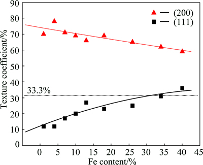
Fig. 3 Texture coefficients of (111) and (200) planes vs Fe content in Ni-Fe alloy coatings
It was reported that the preferred orientations of coatings changed with the change of alloy compositions [19,20]. In the TiSiN coatings [20], with an increase of Si content, the preferred growth orientation of coating was weakened significantly. According to the related theories of coating (or film) preferential growth, the plane with the highest surface free energy is the one that grows the fastest, in order to minimize the energy as far as possible. Finally, the exposing plane is the one that grows the slowest, with the lowest surface free energy.
Among the crystal surfaces that parallel to the matrix surface, the plane that grows the fastest determines the preferred orientation of the coating. By adding alloy elements (especially solid solution elements), the difference of the element itself characteristics (including surface free energy), and the microstrain in the substitutional solid solution will significantly impact the surface free energy of each crystal surface, leading to the change of the growth orientation of coatings.
3.2.3 Lattice constants of coatings
It can clearly be seen that the lattice constant of the alloy increases with increasing Fe content. It has been confirmed in XRD patterns (Fig. 2) that Ni-Fe alloys are solid solutions of Fe in Ni. Since the atomic radius of Fe is larger than that of Ni, with an increase of Fe content, lattice constant of Ni-Fe coating will inevitably increase gradually.
In this work, Rietveld method [21] was used to calculate the lattice constant of Ni-Fe coating with different Fe contents. In terms of nickel diffraction peaks in XRD patterns of Ni-Fe alloy coatings, the relative intensities of (111) and (200) peaks are larger than those of the other peaks. Consequently, in this work, the lattice constants of Ni-Fe coating were estimated by using (111) and (200) diffraction peaks. As shown in Fig. 4, the linear relationship between lattice constant and Fe content of the alloy coating is observed, and the expression of the lattice constant with the change of Fe content is expressed by
a=0.358+0.00009x (2)
where a is the lattice constant of Ni-Fe coating; x is Fe content (mass fraction, %) of Ni-Fe coating.
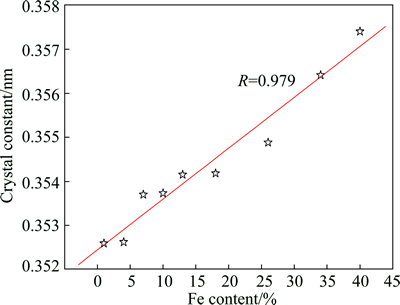
Fig. 4 Lattice constants of Ni-Fe coatings calculated by rietveld method vs Fe content of coating
3.2.4 FWHM and grain size of alloy
FWHM analysis was conducted using the Scherrer equation on the (200) peak, with a correction of instrumental broadening. The FWHM as a function of Fe content in Ni-Fe coatings is shown in Fig. 5. It can be seen from Fig. 5 that with an increase of Fe content, the FWHM increases gradually. Usually, the reasons for peak broadening may be the grain refinement and the increase of stress in the coating [22,23].
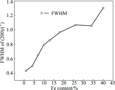
Fig. 5 FWHM vs Fe content in Ni-Fe alloy coatings
In principle, the Bragg peak broadening in an XRD pattern is due to the combination of grain refinement and lattice strain, which can be determined by the integral breadth method [24]. WILLIAMSON and HALL [25] suggested a Cauchy-Cauchy approximation to separate the crystallite size (d) and strain (��). Firstly, assuming that both the crystalline grain size and microstrains contribute to the line broadening, the broadening due to crystallite size (��c) and lattice strain (��s) are represented by
 ,
,  (3)
(3)
where �� is the X-ray wave length of Cu K��, 1.54056  ; �� is Bragg��s diffraction angle (the position of the analyzed peak maximum); d and ��, respectively, indicate the grain size and microstrain of the crystalline phase investigated. The total broadening is the sum of the above contributions. The following relationship holds
 (4)
(4)
Then, Eq. (4) can be turned into
 (5)
(5)
Thus, by plotting ��cos ��/�� against sin ��/��, the microstrain and grain size can be estimated from the slope and the intercept, respectively. In this work, the grain size and microstrain values of Ni-Fe coatings were estimated by using (111) and (200) diffraction peaks.
The grain size in the Ni-Fe alloy coating as a function of Fe content is shown in Fig. 6. When the Fe content decreases below 25% (mass fraction), the grain size increases very rapidly with the decrease of Fe content. This finding is consistent with results in Ref. [4] although they employed different deposition parameters. When the Ni-Fe alloys are deposited, they form solid solutions. Because of the difference in the atomic radius of Fe and Ni (Fe: 0.126 nm, Ni: 0.125 nm), the lattice strain will be produced. With the increase of Fe content, the lattice distortion will be aggravated and result in lattice defects such as dislocation and vacancy. When the number of dislocations accumulates to a certain degree, small-angle grain boundaries will appear, leading to the grain size refinement of the coating. However, the grain size remains approximately constant (~11 nm) for the electrodeposited FCC alloys with Fe content in the range of 25%-40%. This indicates that the grain size of the Ni-Fe coatings is independent of the Fe content in the compositional range of 25%-40%. This is consistent with the results reported for Ni-Fe coatings fabricated from a sulfamate-based bath [26]. The important factors that affect the nucleation rate during the electrodeposition are overpotential and presence of additives [27].
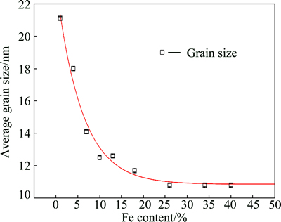
Fig. 6 Average grain size vs Fe content in Ni-Fe alloy coatings
3.2.5 Lattice microscopic strain of coatings
Figure 7 presents the lattice microstrain values and FWHM as a function of the Fe content in Ni-Fe coatings. The lattice microstrain values were calculated based on the method proposed by WILLIAMSON and HALL [25]. While there are some scatters in the values at low Fe contents, the lattice strain increases with increasing the Fe content of the FCC Ni-Fe alloys. The scatter in the alloys with low Fe content can be attributed to the variation in the grain size in these coatings. Since the alloys with Fe content not less than 25% have similar grain sizes (~11 nm), the increase in the lattice strain cannot be attributed to a change in the grain size. The formation of defects such as vacancies, dislocations, voids and twins as well as any local inhomogeneity in the alloys can contribute to the development of lattice strains.
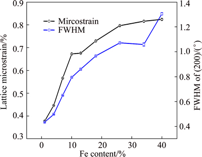
Fig. 7 Lattice microstrain and FWHM vs Fe content in Ni-Fe alloy coatings
3.3 Surface and cross-section morphologies of Ni-Fe coatings
The surface and cross-section morphologies of Ni-Fe alloy coatings with different Fe contents are quite similar. Thus, only the surface and cross-section morphologies of Ni-7Fe coating are shown in Fig. 8. It can be seen from Fig. 8(a) that the surface of Ni-7Fe alloy coating is quite smooth and compact, without any hole or crack. Furthermore, it can also be found that the grain size of Ni-7Fe coating is less than 100 nm. And from Fig. 8(b), the thickness of the coating is about 170 ��m, and the coating is very flat and combines well with the substrate.
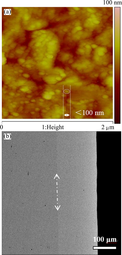
Fig. 8 Surface AFM image (a) and cross-section SEM image (b) of as-deposited Ni-7Fe coating on Ni substrate
4 Conclusions
1) Nanocrystalline Ni-Fe FCC alloys with different compositions were fabricated on nickel substrates using a DC electrodeposition technique. The composition of the coatings was varied by changing the mass ratio of Ni to Fe in the electrolyte.
2) The Fe content of the Ni-Fe alloy coatings has a great influence on the growth preferred orientation, grain size and residual stress. The coatings exhibit preferred orientations of (111) and (200) for FCC alloys. At a low Fe content, the (200) fiber texture is predominant. As the Fe content increases, the (111) fiber texture is strongly developed. Under similar deposition conditions, an increase in the Fe content in the range of 1%-25% results in a significant grain refinement. Increasing the Fe content beyond 25% does not decrease the grain size of FCC alloys any further. The lattice strain increases with increasing the Fe content of the Ni-Fe FCC alloys. Since the alloys with equal or more than 25% Fe have similar grain sizes (~11 nm) the increase in the lattice strain cannot be attributed to a change in the grain size.
References
[1] GHORBANI M, IRAJI ZAD A, DOLATI A, GHASEMPOUR R. The effect of the Cr and Mo on the physical properties of electrodeposited Ni-Fe alloy films [J]. Journal of Alloys and Compounds, 2005, 386(1-2): 43-46.
[2] QIN X Y, KIM J G, LEE J S. Synthesis and magnetic properties of nanostructured ��-Ni-Fe alloys [J]. Nanostructured Materials, 1999, 11(2): 259-270.
[3] SZMAJA W, BALCERSKI J, KOZLOWSKI W, CICHOMSKI M, GROBELNY J, SMONY M, KOWALCZYK P J. Study of thermally evaporated thin permalloy films by the Fresnel mode of TEM and AFM [J]. Journal of Alloys and Compounds, 2012, 521: 174-177.
[4] CHEUNG C, DJUANDA F, ERB U, PALUMBO G. Electrodeposition of nanocrystalline Ni-Fe alloys [J]. Nanostructured Materials, 1995, 5(5): 513-523.
[5] HARRIS V G, GEILER A, CHEN Y, YOON S D, WU M, YANG A, CHEN Z, HE P, PARIMI P V, ZUO X, PATTON C E, ABE M, ACHER O, VITTORIA C. Recent advances in processing and applications of microwave ferrites [J]. Journal of Magnetism and Magnetic Materials, 2009, 321(14): 2035-2047.
[6] WANG Y, TENG X, WANG J S, YANG H. Solvent-free atom transfer radical polymerization in the synthesis of Fe2O3@polystyrene core-shell nanoparticles [J]. Nano Letters, 2003, 3(6): 789-793.
[7] GENG Shu-jiang, LI Yan-dong, XIANG Dong, ZHOU Shi-gang. Electrodeposition of Fe-Ni alloy coating on ferritic stainless steel [J]. Transactions of Nonferrous Metals Society of China, 2010, 20(S1): s226-s230.
[8] MA L, ZHOU K, LI Z, WEI Q, ZHANG L. Hot corrosion of a novel NiO/NiFe2O4 composite coating thermally converted from the electroplated Ni-Fe alloy [J]. Corrosion Science, 2011, 53(11): 3712-3724.
[9] MURALIDHARAN S, SARASWATHY V, BERCHMANS L J, THANGVEL K, ANN K Y. Nickel ferrite (NiFe2O4): A possible candidate material as reference electrode for corrosion monitoring of steel in concrete environments [J]. Sensors and Actuators B: Chemical, 2010, 145: 225-231.
[10] CHEN Duan, ZOU Zhong, TIAN Zhong-lian, XIN Pang-fei, LIU Kai, LAI Yan-qing, LI Jie. Effect of sintering atmosphere on phase composition and mechanical properties of 5Ni/(10NiO-NiFe2O4) [J].Transactions of Nonferrous Metals Society of China, 2012, 22(1): 124-128.
[11] ZHOU Ke-chao, MA Li, LI Zhi-you. Oxidation behaviors of electrodeposited Nickel-cobalt coatings at 960 ��C in air [J]. Transactions of Nonferrous Metals Society of China, 2011, 21(5): 1052-1060.
[12] RAHMAN A, JAYAGANTHAN R, PRAKASH S, CHAWLA V, CHANDRA R. High temperature oxidation behavior of nanostructured Ni-Al coatings on superalloy [J]. Journal of Alloys and Compounds, 2009, 472(1-2): 478-483.
[13] HERCHL R, KHOI N N, HOMMA T, SEMELTZER W W. Short- circuit diffusion in the growth of nickel oxide scales on nickel crystal faces [J]. Oxidation of Metals, 1972, 4(1): 35-49.
[14] MA L, ZHOU K C, ZHANG L, LI Z Y. A study on the oxidation behavior of nickel coatings with different grain sizes and preferred orientations [J]. Advanced Materials Research, 2011, 183-185: 1762-1766.
[15] YIN K M, LEE C C. Effect of ferrous ion concentration on the electrodeposition of iron�Cnickel alloys [J]. Journal of Chemical Technology & Biotechnology, 1997, 70(4): 337-342.
[16] ZECH N, PODLAHA E J, LANDOLT D. Anomalous codeposition of iron group metals. I. Experimental results [J]. Journal of the Electrochemical Society, 1999, 146(8): 2886-2900.
[17] NGUYEN A M, CERCELARU S, TREMBLAY G, PERRON J C, HESTO P. Magnetic and electrical characterizations of thin Ni-Fe and Ni-Fe-Mo films [J]. Thin Solid Films, 1996, 275(1-2): 231-234.
[18] CHEN L, WANG L ZENG Z, XU T. Influence of pulse frequency on the microstructure and wear resistance of electrodeposited Ni-Al2O3 composite coatings [J]. Surface and Coatings Technology, 2006, 201(3-4): 599-605.
[19] KIM G, KIM B, LEE S. High-speed wear behaviors of CrSiN coatings for the industrial applications of water hydraulics [J]. Surface and Coatings Technology, 2005, 200(5-6): 1814-1818.
[20] DISERENS M, PATSCHEIDER J, LEVY F. Improving the properties of titanium nitride by incorporation of silicon [J]. Surface and Coatings Technology, 1998, 108-109: 241-246.
[21] YOUNG R A. The rietveld method [M]. Oxford: Oxford University Press, 1993.
[22] GORCZYCA I, CHRISTENSEN N E, PERLIN P, GRZEGORY I, JUN J, BOCKOWSKI, M. High pressure phase transition in aluminium nitride [J]. Solid State Communications, 1991, 79(12): 1033-1034.
[23] WUHRER R, YEUNG W Y. A comparative study of magnetron co-sputtered nanocrystalline titanium aluminium and chromium aluminium nitride coatings [J]. Scripta Materialia, 2004, 50(12): 1461-1466.
[24] ISHIKAWA N, YAMAMOTO S, CHIMI Y. Structural changes in anatase TiO2 thin films irradiated with high-energy heavy ions [J]. Nuclear Instruments and Methods in Physics Research Section B: Beam Interactions with Materials and Atoms, 2006, 250(1-2): 250-253.
[25] WILLIAMSON G K, HALL W H. X-ray line broadening from filed aluminium and wolfram [J]. Acta Metallurgica, 1995, 1(1): 22-31.
[26] LI H, EBRAHIMI F. Synthesis and characterization of electrodeposited nanocrystalline nickel�Ciron alloys [J]. Materials Science and Engineering A, 2003, 347(1-2): 93-101.
[27] WALSH F C, HERRON M E. Electrocrystallization and electrochemical control of crystal growth: Fundamental considerations and electrodeposition of metals [J]. Journal of Physics D: Applied Physics, 1991, 24(2): 217-225.
NiFe2O4�⾧ʯͿ��������Ni-Fe�Ͻ�ĵ�����Ʊ������
�� ��1, 2���� ��2����С��1����־��2���ܿƳ�2
1. ���ϴ�ѧ ұ���뻷��ѧԺ����ɳ 410083��
2. ���ϴ�ѧ ��ĩұ������ص�ʵ���ң���ɳ 410083
ժ Ҫ������ֱ�������������Ni�������Ʊ�Fe����Ϊ1%~39%(��������)������FCC Ni-Fe�Ͻ�Ϳ�㡣����X�������似���о�Ni-Fe�Ͻ�Ϳ��ľ���ṹ������Ӧ�䡢�����ߴ�;�����������X����������ɢ����(EDS)��ԭ��������(AFM)����������Ļ�ѧ�ɷֺͱ�����̬�����������Fe�����������Ͻ�����������ȡ�����ߴ硢�������;���Ӧ���нϴ�Ӱ�졣FCC Ni-Fe�Ͻ�Ϳ�������ȡ��Ϊ(200)��(200)(111)������Fe���������ӣ�(200)���������ȡ����������(111) ���������ȡ������ǿ����Fe����Ϊ1.3 %~ 25%(��������)ʱ��Fe����������ʹ������ľ�������ϸ������Fe��������25%ʱ��Fe���������Ӳ���ʹFCC Ni-Fe�Ͻ����ߴ��С��FCC Ni-Fe�Ͻ�ľ���Ӧ����Fe���������Ӷ���������Fe����������25%�ĺϽ�������Ƶľ����ߴ�(ԼΪ11 nm)�����Ծ���Ӧ����Fe���������Ӳ��ܹ����ھ����ߴ�ı仯��
�ؼ��ʣ�Ni-Fe�Ͻ𣻵������������NiFe2O4�⾧ʯ��Ϳ��
(Edited by Wei-ping CHEN)
Foundation item: Project (51021063) supported by the National Natural Science Fund for Innovation Group of China; Project (2012M521540) supported by China Post Doctoral Science Foundation; Project (2013RS4027) supported by the Post Doctoral Scientific Foundation of Hunan Province, China; Project (CSUZC2013023) supported by the Precious Apparatus Open Share Foundation of Central South University, China
Corresponding author: Ke-chao ZHOU; Tel: +86-731-88836264; E-mail: zhoukc2@csu.edu.cn
DOI: 10.1016/S1003-6326(15)63589-0
Abstract: Nanocrystalline Ni-Fe FCC alloy coatings with Fe content of 1.3%-39% (mass fraction) were fabricated on the nickel substrates using a DC electrodeposition technique. The crystal structure, lattice strain, grain size and lattice constant of the Ni-Fe alloy coatings were studied by X-ray diffraction technique. The chemical composition and surface morphology of the FCC Ni-Fe alloy coatings were investigated with the energy dispersive X-ray spectroscopy (EDS) and atomic force microscopy (AFM). The results show that the Fe content of the Ni-Fe alloy coatings has a great influence on the preferred orientation, grain size, lattice constant and lattice strain. FCC Ni-Fe alloy coatings exhibit preferred orientations of (200) or (200)(111). With an increase of Fe content, the preferred growth orientation of (200) plane is weakened gradually, while the preferred growth orientation of (111) increases. An increase of the Fe content in the range of 1.3%-25% (mass fraction) results in a significant grain refinement of the coatings. Increasing the Fe content beyond 25% does not decrease the grain size of FCC Ni-Fe alloys further. The lattice strain increases with increasing the Fe content in the FCC Ni-Fe alloys. Since the alloys with Fe content not less than 25% has similar grain size (~11 nm), the increase in the lattice strain with the increase of Fe content cannot be attributed to the change in the grain size.
