

Characteristics of two Al based functionally gradient composites reinforced by primary Si particles and Si/in situ Mg2Si particles in centrifugal casting
ZHAI Yan-bo(���岩), LIU Chang-ming(������), WANG Kai(�� ��), ZOU Mao-hua(��ï��), XIE Yong(л ��)
College of Material Science and Engineering, Chongqing University, Chongqing 400030, China
Received 26 December 2008; accepted 4 May 2009
Abstract:
Two kinds of Al based functionally gradient composite tubes reinforced by primary Si particles alone and primary Si/ in situ Mg2Si particles jointly were successfully prepared by centrifugal casting, and their structural and mechanical characters were compared. It is found that the composite reinforced with primary Si particles takes a characteristic of particles distribution both in the inner and outer layers. However, composite reinforced with primary Si/Mg2Si particles jointly takes a characteristic of particles distribution only in the inner layer and shows a sudden change of particles distribution across the section of inner and outer layers. The hardness and wear resistance of Al-19Si-5Mg tube in the inner layer are greatly higher than that in the other layers of Al-19Si-5Mg tube and Al-19Si tube. Theoretical analysis reveals that the existence of Mg2Si particles is the key factor to form this sudden change of gradient distribution of two kinds of particles. Because Mg2Si particles with a lower density have a higher centripetal moving velocity than primary Si particles, in a field of centrifugal force, they would collide with primary Si particles and then impel the later to move together forward to the inner layer of the tube.
Key words:
centrifugal casting; functionally gradient composites; in situ primary Si particles; in situ Mg2Si particles;
1 Introduction
The concept of functionally gradient material (FGM) was firstly reported in 1980s by researchers of Japan[1]. Compared with traditional materials, the main merits of the functionally gradient composites are that their performance and microstructure may be designed and controlled. Thus, the intensity, toughness, rigidity, optics, electricity and thermodynamics characteristics can be artificially designed and controlled to satisfy different application situations[2]. Common methods used to prepare functionally gradient composites are built-up welding, laser melting, double-current casting, gas phase deposition, hot spraying duplicate, power metallurgy and so on[3]. Recently, along with the unceasing progress of the hyper-eutectic Al-Si alloy crystal grain refinement research work, as well as wide applications of Al-Si functionally gradient composites in the industries of automobile, astronautics and the electronic seal domain, in situ primary Si particle reinforced Al based functionally gradient composites and in situ Mg2Si particles reinforced Al based functionally gradient composites were paid more and more attention by researchers all over the world[4-6]. TOMIDA et al[7] prepared primary Si particle reinforced surface functionally gradient composites by laser surface remelting process. NIKANOROV et al[8] prepared hyper-eutectic Al-Si functionally gradient composites by remelting and fast cooling process. PUT et al[9] prepared hyper-eutectic Al-Si functionally gradient composites by electrophoretic deposition process. TAN[10-11] prepared a single kind of in situ primary Si particles to reinforce Al based functionally gradient composites using centrifugal casting process. SONG et al[12] prepared Al-Si functionally gradient composites by electromagnetic separation method. ZHANG et al[13] prepared single kind of in situ Mg2Si particles to reinforce Al based functionally gradient composites using centrifugal casting process. QIN et al[14-16] prepared single kind of Mg2Si particles to reinforce Al based functionally gradient composites using an electric arc remelting technology. However, there were some limits by introducing only the single primary Si or Mg2Si as reinforced particles into functionally gradient composites. If the quantity of Si or Mg2Si particles is higher, not only the castability of an alloy is weakened, but also the primary Si or Mg2Si particles grows up quickly to form coarse ones, which leads Si or Mg2Si particles slough off easily from matrix of the alloy under a stress when in using[17]. On the other hand, if the quantity of Si or Mg2Si particles is lower, a perfect effect of reinforcement can not be achieved. In order to overcome the shortages mentioned above, Mg element can be added into an Al-Si alloy and its quantity may be adjusted to form both Mg2Si and primary Si particles to reinforce composites[18]. In this work, two kinds of Al-Si alloys or composites without Mg and with partial Mg were prepared using centrifugal casting process, and the characteristics of structures and mechanical properties of two alloys or composites in centrifugal casting were compared.
In centrifugal casting technology, density difference between particles and a fused mass of master alloy were used to prepare in situ primary Si or Mg2Si particles reinforced Al based functionally gradient function composites under a centripetal force[19]. This force impels the particles moving toward the core location to form a reinforced region in inner layer of the tube. Because the primary Si particles have a higher micro-hardness, 12 308 MPa for primary Si particle and 4 410 MPa for Mg2Si[17], and excellent thermal stability, the reinforced layers possess a higher hardness, an excellent wear resistance and a thermal stability. This kind of functionally gradient composites is hopefully applied as engine cylinder liner, piston or electronic seal material[5].
2 Experimental
2.1 Materials
Commercial Zl104 alloy, AZ91D alloy and Al-29Si high Si alloy were taken as raw materials. Al-19Si alloy and Al-19Si-5Mg alloy were respectively smelted using these raw materials.
2.2 Experimental process
2.2.1 Smelting
Same smelting process was adopted to make two different ingredient alloys. Firstly, 20 kg prepared raw material was smelted at 750 �� in an electrical resistance furnace. Secondly, hexachloroethane of 0.6% (mass fraction) of total quantity of the melt was added into the melt for the first fining processing. Thirdly, the melt was heated up to 820 �� and then, PM (powder metallurgy) modificator of 1.6% (mass fraction) was pressed into the melt using a plunger to carry on modification. Finally, the melt was heated-up to 840 �� and treated for the last fining processing by inert gas of argon. The melt was kept at 840 �� for pouring.
2.2.2 Casting
Hot mold casting was adopted. The casting mould was preheated to 220-250 ��, and the centrifugal rotational speed was controlled at 2 000 r/min. The mass of poured liquid was controlled to about 2.5 kg by a quantitative casting ladle. The dimension of the tube obtained was 109 mm in external diameter, 15 mm in wall thickness and 190 mm in length. Fig.1 shows its shape and dimensions.
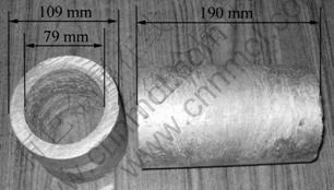
Fig.1 Composites material tubes obtained by centrifugal casting
2.3 Structure observation and phase analysis
2.3.1 Structure observation
Along the radial direction in the wall of the tube, samples with 10 mm width were taken in the middle of the tubular pieces, then sanded and polished for structure observation. A digital photographic camera and a metallography light microscope were introduced to carry out.
2.3.2 Phase analysis
The Al-19Si alloy is a typical Al alloy, so the phase analysis is mainly aiming at the Al-19Si-5Mg alloy. XRD (X-ray Diffraction), SEM (Scanning Electron Microscopy) and EDS (Energy Dispersive Spectrometer) methods were adopted.
2.4 Rockwell hardness and friction testing
2.4.1 Rockwell hardness testing
TIME TH300 Rockwell hardness apparatus (1.587 mm steel ball, 100 kg) was adopted to test HRB hardness. Testing sites were located in inner layer��intermediate layer and outer layer respectively, as shown in Fig.2.
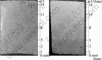
Fig.2 Cross-section macroscopic appearances: (a) Al-19Si; (b) Al-19Si-5Mg tubes
2.4.2 Friction testing
Friction test was taken on a self-refiting friction testing machine. The friction disk was a carborundum grinding head with a diameter of 8 mm. In the friction test, the rubbing time was 10 min and the total friction force was 200 N (the pressure was 4��106 Pa). The wear mass loss of a specimen was weighed by 0.1 mg precision analytical balance and then, it was converted to the volume loss according to the actual density of debris from a specimen rubbed.
3 Results
3.1 Macroscopic appearance characteristics of sections of tubes
Fig.2 shows the macroscopic appearances of sections of Al-19Si and Al-19Si-5Mg tubes which were photoed by a digital photographic camera. According to the macroscopic appearance characteristics of sections, the wall of tubes is divided into three layers as shown in Fig.2, the inner layer, which is a region of 0-5 mm apart from the inwall, the intermediate layer, which is a region of 5-11 mm apart from the inwall, and the outer layer, which is a region of 11-15 mm apart from the inwall. It is seen from Fig.2(a) that the particles mainly distribute in the inner layer and the outer layer, and also a few particles assemble in the intermediate layer. Therefore, it is concluded that after the centrifugal cast forming, the Al-19Si alloy forms the gradual functionally gradient composites tube in which both the inner layer and outer layer in its radial cross section are reinforced with particles.
It can be seen from Fig.2(b) that after centrifugal cast forming, reinforcement particles are mostly completely gathered in the inner layer with a thickness of about 5 mm, only an 0.5 mm or so thickness region of enhancement particles exist in the most outer layer of the tube. There is an obvious borderline between the inner layer and the intermediate layer, a new concept of ��sudden change�� functionally gradient composites is adopted in this research.
Through the contrast and analyzing above, it is concluded that Mg is a key factor of forming Al-Si sudden change functionally gradient composites in the same smelting and centrifugal casting process.
3.2 Results of phase analysis
Fig.3 shows XRD patterns of Al-19Si-5Mg tube at inner layer (0-5 mm), intermediate layer (5-11 mm) and outer layer (11-15 mm), respectively. There are approximate phase compositions of Al, Si and Mg2Si in the three layers. Mg leads to the emergence of Mg2Si phase as a certain amount of Mg is added into the Al-Si alloy. The density of Mg2Si is 1.93 g/cm3, the density of primary Si is 2.34 g/cm3, and the density of Al-Si alloy is 2.37 g/cm3[17]. The density of Mg2Si is smaller than that of primary Si and Al-Si alloy.
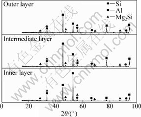
Fig.3 XRD patterns of Al-19Si-5Mg tube
Fig.4 shows the SEM morphologies of the reinforcement layer and un-reinforcement layer of Al-19Si-5Mg tube. Tables 1 and 2 show the results of energy spectrum analysis for Si, Al and Mg. Combined with the results of XRD, SEM and EDS analyses, primary Si, eutectic Si, primary Mg2Si, eutectic Mg2Si and �� can be defined. As shown in Fig.4(a), points 1, 2, 3 and 4 mark the primary Mg2Si, primary Si, �� and eutectic Si, respectively. As shown in Fig.4(b), points 1, 2 and 3 mark the ��, eutectic Si and eutectic Mg2Si, respectively.
Table 1 EDS results in Fig.4(a) (mole fraction, %)
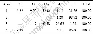
Table 2 EDS results in Fig.4(b) (mole fraction, %)
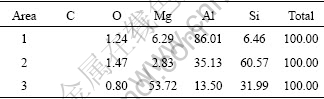
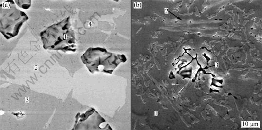
Fig.4 SEM images of Si, Mg2Si and EDS points of Al-19Si-5Mg tube: (a) Primary Si, Mg2Si and Al; (b) Eutectic Si, Mg2Si and Al
3.3 Microstructure of sections
Fig.5 shows the microstructures of an Al-19Si tube at different locations in radial section. Fig.5(a), (b), (c), (d), (e) and (f) respectively present microstructures at locations of 1, 3, 5, 8, 11, and 14 mm apart from the inwall of the tube as shown in Fig.2(a).
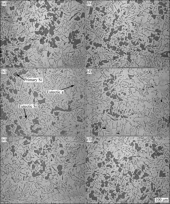
Fig.5 SEM images of Al-19Si tube in Fig.2(a): (a) 1-3 mm; (b) 3-5 mm; (c) 5-8 mm; (d) 8-10 mm; (e) 10-14 mm; (f) 14-15 mm
Fig.6 shows the microstructures of an Al-19Si-5Mg tube at different locations in radial section. Fig.6(a), (b), (c), (d), (e) and (f) respectively present microstructures at locations of 1, 3, 5, 8, 11, and 14 mm apart from the inwall of the tube as shown in Fig.2(b).
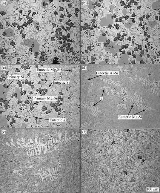
Fig.6 SEM images of Al-19Si-5Mg tube in Fig.2(b): (a) 1-3 mm; (b) 3-5 mm; (c) 5-8 mm; (d) 8-10 mm; (e) 10-14 mm; (f) 14-15 mm)
According to the results of XRD, SEM, and EDS and microstructure characteristics of hyper-eutectic Al-Si alloy[17, 20-21], it can be determined that in Fig.6, the massive black lumps are primary Mg2Si particles and the tiny black network structure is eutectic Mg2Si phase[17, 22-23], as shown in Fig.7. Fig.7 shows an enlarged network microstructure of Mg2Si in eutectics under an optical microscope. The tiny black network structure is named eutectic Mg2Si. From Fig.5 and Fig.6, the following microstructure differences between Al-19Si tube and Al-19Si-5Mg tube can be found.
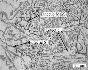
Fig.7 SEM image of network microstructures in intermediate layer of Al-19Si-5Mg tube
1) Types and quantities of reinforcement particles
As shown in Fig.5 and Fig.6, there is only primary Si particle as reinforcement phase in the Al-19Si tube, but primary Si and Mg2Si particles coexist in the Al-19Si-5Mg tube. At the same time, because Si element is consumed to form Mg2Si by adding Mg into the melt, the quantity of primary Si particles in Al-19Si-5Mg tube is lower than that in the Al-19Si tube, as shown in Fig.8 and Fig.9 that are obtained by area estimating. However, the consumed Mg forms the massive tiny black Mg2Si particles (e.g. Figs.6(a)-(c) and (f) ) and a few network eutectic Mg2Si (e.g. Fig.9 and Fig.4(b)).
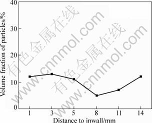
Fig.8 Primary Si particles distribution curve in Al-19Si tube
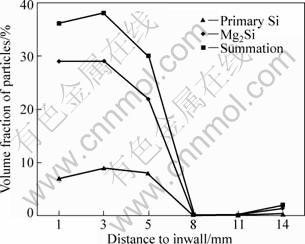
Fig.9 Primary Si and Mg2Si particles distribution curve in cross-section of Al-19Si-5Mg tube
2) Particles gathering characteristic
In Fig.5, the primary Si particles present a gradual gradient distribution tendency. In the inner layer (Figs.5(a) and (b)), primary Si particles distribute evenly, and take up a higher volume fraction. Along with the wall thickness increasing, the quantity of particles reduces gradually (e.g. Fig.5(c)). In the intermediate layer (Figs.5(d) and (e)), the volume fraction of the particles is the lowest, and they distribute the form of non-aggregation. In the outer layer (Fig.5(f)), a mass of particles appear again. The quantitative analysis result of primary Si particles distribution in Fig.8 shows that primary Si particles have not really been aggregated in the inwall of the tube. Different from Fig.5, in Fig.6 the inner layer (Figs.6(a)-(c)) gathers a vast gray primary Si and black Mg2Si particles. In the intermediate layer (Figs.6(d) and (e)), nearly no particles appear and microstructure mainly consists of Al-Si eutectic, dendritic �� phase and a few black eutectic Mg2Si. In the outer layer (Fig.6(f)), a few primary Si and Mg2Si particles appear again, but the size of the particles is smaller than that in the inner layer. Contrasting Fig.5(f) and Fig.6(f), the volume of particles in Al-19Si-5Mg is much smaller than that in Al-19Si tube in the same outer layer. This is because the velocity of primary Si particles in Al-19Si tube is slower than that of coagulation, a number of primary Si particles is retained in the outer layer. But as to Al-19Si-5Mg tube, the multiple primary particles are shifted before the freezing face arrives in the same mould cooling condition with Al-19Si tube, so only a few particles remain. The quantitative analysis results of primary Si and Mg2Si particles distribution are shown in Fig.9, which shows the sudden changes of distributions of primary Si and Mg2Si particles in the direction of the thickness of the tube.
3) Appearances of particles
It can be seen in Fig.5 that primary Si particles in the Al-19Si tube are uniform and tiny, and the size of particles is 30-50 ��m. Different from Fig.5, the particles in the inner layer of Al-19Si-5Mg tube aggregate seriously in Fig.6. Several primary Si particles stick up together and primary Mg2Si particle is wrapped up by primary Si particles to form a big single mix particle, as shown in Figs.6(a)-(c). In the most outer layer (Fig.6(f)), particles are tiny and even, and the aggregation of particles does not occur. According to a staff guage, the size of primary Si particles in the inner layer is 80-120 ��m and is about 30 ��m in the outer layer. As for Mg2Si particles, the size is 30-40 ��m in the inner layer and is about 30 ��m in the outer layer.
3.4 Results of hardness and friction tests
Fig.10 and Fig.11 show the results of hardness and friction tests of Al-19Si tube and Al-19Si-5Mg tube, respectively. It can be seen from these two figures, that, 1) in the inner layer of Al-19Si-5Mg tube, the hardness is the highest and the volume loss is the lowest, but for Al-19Si tube, the highest hardness and the lowest volume loss appear in the outer layer, and 2) in the tube of Al-19Si-5Mg, the hardness at the inner layer is obviously greater than that in the intermediate layer and the outer layer; the volume loss at the inner layer is about one third smaller than that in the intermediate layer and the outer layer; however, in the tube of Al-19Si, there are no great differences of hardness and volume loss between three layers.
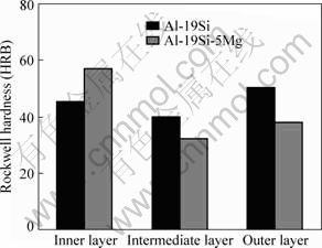
Fig.10 Rockwell hardness of three layers of two tubes
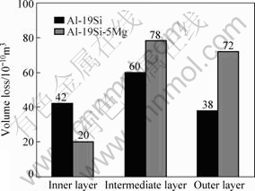
Fig.11 Wearing capacity of three layers of two tubes
As to the Al-19Si tube, 11%-13% (volume fraction) of primary Si reinforcement particles are distributed in the inner layer and outer layer, therefore, there are relatively higher hardness and wear resistance in the inner layer and outer layer than that in the intermediate layer. As to the outer layer, due to the effect of splat cooling of the mould, the structure is thinner and more compact than that in the inner layer, so the hardness and wear resisting property are better than those in the inner layer. As to Al-19Si-5Mg tube, 30%-38% reinforcement particles are distributed in the inner layer, so the reinforcement effect of two kinds of particles occupies a dominant position in the process of hardness and friction tests and it leads the inner layer to hold the highest hardness and wear resistance. In the intermediate layer, thick eutectics and �� dentrites make the hardness and the wear resistance to reduce violently. In the outer layer, a spot of reinforcement particles makes the hardness and the wear resistance a little higher than that in the intermediate layer.
4 Particles assembling mechanism in centrifugal force field
4.1 Stress and movement velocity relationship of primary Si and Mg2Si particles in centrifugal force field
A particle receives a centrifugal force Fc, a centrifugal floatage Fr, and a viscous resistance Fd in a centrifugal force field, as shown in Fig.12, and,
Fc=mpr��2 (1)
Fd=3�Ц�dpvp (2)
Fr=mLr��2 (3)
So the resultant force of the particles received is
F=Fr-Fc-Fd=mLr��2-mpr��2-3��dpvp (4)

Fig.12 Stress of particles along radial direction
where F is the resultant force of the particles received; Fc is the centrifugal force of the particles received; Fd is the viscous resistance of the particles received among moving; Fv is the centrifugal floatage of the particles received; mp is the quality of particles; mL is the quality of fused mass exhausted by particles; r is centrifugal radius; �� is the revolution angular velocity; dp is the diameter of particles; vp is the velocity of the particles and �� is the viscosity coefficient of the particles.
It can be seen from Eq.(4) that the motion model of the particles in the centrifugal fields is very complex. In order to simplify the model and only analyse the stress of particles, we may presume that the initial velocity of particles is zero, in other words, only the incipient stage of forming the in situ particles is considered. And thus Eq.(4) is changed into
F=Fr-Fc=mLr��2-mpr��2 (5)
According to Ref.[19], Eq.(5) can be simplified again as:
F=0.01vRn2(��1-��2) (6)
where ��1 is the fused mass density and ��2 is the density of reinforcement particles.
The centripetal acceleration of reinforcement particles, ��c, can be derived as:
![]()
![]()
![]() (7)
(7)
In composite material slurry, the densities of primary Si, Mg2Si and fused Al mass are 2.33 g/cm3, 1.93 g/cm3 and 2.37 g/cm3, respectively. Substituting these data into Eq.(7), the centripetal accelerations of primary Si and Mg2Si particles can be obtained as:
For primary Si particle
![]() (8)
(8)
For Mg2Si particles
![]() (9)
(9)
In an identical centrifugal radius, the ratio of centripetal acceleration (n) of Mg2Si and primary Si particles is
![]() (10)
(10)
As the initial velocity is zero, the relationship between acceleration and speed can be given as:
v=at (11)
From Eqs.(10) and (11), it may be inferred that, at an identical spot of centrifugal casting mould, the centripetal moving velocity of Mg2Si particle is 13.9 times that of the primary Si particle.
4.2 Assembling mechanism of primary Si and Mg2Si particles in centrifugal stress field
Through analyzing stress and velocity relationship of primary Si and Mg2si particles, it is found that Mg2Si particles are much easier to move toward the inner layer than primary Si in the same condition, because its centripetal moving velocity is 13.9 times that of primary Si. Considering microstructures characteristic of Al-19Si and Al-19Si-5Mg tubes shown in Figs.5 and 6, the assembling model of two kinds of particles can be established as shown in Fig.13.
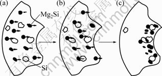
Fig.13 Schematic of primary Si and Mg2Si particles assembling in off-centering field: (a) Particles forming; (b) Mg2Si particles colliding with primary Si particles and moving together; (c) Mg2Si wrapped by primary Si particles and primary Si particles adhere each other
The first stage of the model is the particles formation in outer layer, as shown in Fig.13(a). After melt is poured into a casting mould, for the effect of chilling of metal mould on the melt, the melt that contacts with the surface of cavity of the mould freezes so quickly that there is no enough time for particles to move and they are retained at the outer layer, as shown in Fig.5(f) and Fig.6(f).
The second stage is the moving of two kinds of particles toward the inner layer, as shown in Figs.13(b), 14(a)-(b). When the melt in the most outer layer freezes, it releases a massive crystallization latent heat that causes the melt in the intermediate layer and inner layer to keep a liquid state. Under this condition, primary Si and Mg2Si particles, whose densities are smaller than that of the melt, start to move toward the inner layer under an effect of the centrifugal force. Because the centripetal acceleration of Mg2Si particle is 13.9 times that of primary crystal Si, the centripetal velocity of Mg2Si particle is higher than that of primary Si particle by far. As massive tiny Mg2Si particles move toward the inner layer, they collide with primary Si particles which move slower relatively, as shown in Fig.13(b) and Fig.14(a). After collision, the Mg2Si particles impel the primary Si particles moving together at a higher speed, as shown in Fig.6(c) and 14(b). As there is no effect of impelling of the Mg2Si particles, the primary Si particles with a slower moving velocity, remained in the intermediate layer and form a microstructure characteristic as shown in Fig.5.
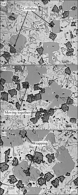
Fig.14 Process of Mg2Si particles colliding, adhering with primary Si
The third stage is that primary Si particles adhere together and some of Mg2Si particles are wrapped up by the primary Si particles, as shown in Fig.13(c) and Fig.14(c). When several Mg2Si particles impel a primary crystal Si particle together moving to the inner layer, they still have a higher velocity. And now, if in front of the Mg2Si particles, there is a primary Si particle or a primary Si particle mixing with Mg2Si particles moving with a slower movement velocity, these two groups would collide and this collision results in a Mg2Si particle to be wrapped by primary Si particles or several primary Si particles be adhered together, as shown in Figs.6(a)-(c) and Fig.14(c). This kind of mixed movement and the adhesion model causes the primary Si particle in the inner layer in Al-19Si-5Mg tube to be much bigger than that in Al-19Si tube.
Therefore, in the process of preparing primary Si and Mg2Si particles reinforced Al-Si gradient function composite material tube by centrifugal casting, the Mg2Si particle is the key aspect to promote particles to assemble and form a sudden change of gradient function distribution of the particles.
5 Conclusions
1) Al-19Si and Al-19Si-5Mg functionally gradient composites tubes that are reinforced by in situ particles were successfully prepared by hot mold centrifugal casting process. It is demonstrated by XRD analysis that the reinforcement particles in Al-19Si tube are single kind of primary Si particles and are primary Si particles mixing with Mg2Si particles in Al-19Si-5Mg tube.
2) Macroscopic appearance of two kinds of tubes reveals that, the Al-19Si tube takes on gradual gradient characteristic and primary Si particles mainly distribute both in the inner layer and outer layer; but for the Al-19Si-5Mg tube, reinforcement particles of primary Si particles and Mg2Si particles distribute only in the inner layer and take on a sudden change gradient characteristic.
3) Microstructure appearance of two kinds of tubes reveals that, particles in the Al-19Si tube reinforced by primary Si particles alone are even and tiny; but in Al-19Si-5Mg tube reinforced by both primary Si particles and Mg2Si particles, they are wrapped up or adhere together to cause an increase of primary Si particles size obviously.
4) The tube of Al-19Si-5Mg possesses a higher hardness and wear resistance than the tube of Al-19Si in the inner layer. As to Al-19Si tube, a relatively high hardness and wear resistance appear in the outer layer; however, as to Al-19Si-5Mg tube, the highest hardness and wear resistance appear in the inner layer. Hardness and wear resistance of Al-19Si-5Mg tube in the inner layer are greatly higher than those in the other layers of Al-19Si-5Mg tube and Al-19Si tube.
5) The assembling mechanism analyzing reveals that the Mg2Si particle is a key aspect of forming the sudden change functionally gradient composites tubes. In a centrifugal force field, the centripetal accelerations of Mg2Si particles with smaller density is 13.9 times that of primary Si particles, so its centripetal movement velocity is higher than that of primary Si particles by far. During moving toward the center, massive tiny Mg2Si particles collide and adhere with primary Si particles and then, Mg2Si particles impel primary Si particles moving together and a sudden change functionally gradient composite reinforced by two kinds of in situ particles is formed.
References
[1] MATSUZAK F. Production of functionally gradient materials (FGM) by a gas pressure combustion sintering process [J]. Powder and Powder Metall, 1990, 37(7): 937-941.
[2] KAWASAKI A. Concept and P/M fabrication of functionally gradient materials [J]. Ceramics International, 1997, 23(1): 73-83.
[3] HAO Yuan-kai, XIAO Jia-yu. High Performance composite materials [M]. Beijing: Chemical Industry Press, 2004: 209-226. (in Chinese)
[4] LU De-hong, JIANG Ye-hua, GUAN Gui-sheng. Refinement of primary Si in hypereutectic Al-Si alloy by electromagnetic stirring [J]. Journal of Materials Processing Technology, 2007, 189: 13-18.
[5] MA Ming-tu, SHA Wei. Progress of Material Science and Engineering. Mechanical Industry Press [M]. Beijing: China Machine Press, 2000: 629-670. (in Chinese)
[6] DHEERENDRA K D. Wear behaviour of cast hypereutectic aluminium silicon alloys [J]. Materials and Design, 2006, 27: 610-616.
[7] TOMIDA S, NAKATA K, SHIBATA S. Improvement in wear resistance of hyper-eutectic Al-Si cast alloy by laser surface remelting [J]. Surface and Coating Technology, 2003, 169/170: 468-471.
[8] NIKANOROV S P, VOLKOV M P, GURIN V N. Structural and mechanical properties of Al-Si alloys obtained by fast cooling of a levitated melt [J]. Materials Science and Engineering A, 2005, 390: 63-69.
[9] PUT S, VLEUGELS J. Microstructural engineering of functionally graded materials by electrophoretic deposition [J]. Journal of Materials Processing Technology, 2003, 143/144: 572-577.
[10] TAN Yin-yuan. In situ gradient composites of Al-16wt Si alloy by centrifugal casting [J]. Acta Materiae Compositae Sinica, 2002, 19(5): 48-51. (in Chinese)
[11] TAN Yin-yuan. In situ gradient composite of hypereutectic Al-Si alloy by centrifugal casting and its damping property [J]. The Chinese Journal of Nonferrous Metals, 2002, 12(2): 353-357. (in Chinese)
[12] SONG Chang-jiang, XU Zhen-ming, LI Jian-guo. Structure of in situ Al/Si functionally graded materials by electromagnetic separation method [J]. Materials and Design, 2007, 28: 1012-1015.
[13] ZHANG Jiang, FAN Zhong-yun, WANG Yu-qing, ZHOU Ben-lian. Hypereutectic aluminium alloy tubes with graded distribution of Mg2Si particles prepared by centrifugal casting [J]. Materials and Design, 2000, 21: 149-153.
[14] QIN Q D, ZHAO Y G, LIU C, CONG P J, ZHOU W. Strontium modification and formation of cubic primary Mg2Si crystals in Mg2Si/Al composite [J]. Journal of Alloys and Compounds, 2008, 454: 142-146.
[15] QIN Q D, ZHAO Y G, CONG P J, LIANG Y H, ZHOU W. Multi-layer functionally graded Mg2Si/Al composite produced by directional remelting and quenching process [J]. Materials Science and Engineering A, 2006, 418: 193-198.
[16] QIN Q D, ZHAO Y G, CONG P J, LIANG Y H, ZHOU W. Functionally graded Mg2Si/Al composite produced by an electric arc remelting process [J]. Journal of Alloys and Compounds, 2006, 420: 121-125.
[17] WANG Zhao-tang, TIAN Rong-zhang. Al alloys and machining manual [M]. Changsha: Central South University of Technology Press, 1989: 456-478. (in Chinese)
[18] LIU Hong, ZHAO Gang, LIU Chun-ming, ZUO Liang. Effects of magnesium content on phase constituents of Al-Mg-Si-Cu alloys [J]. Transactions of Nonferrous Metals Society of China, 2006, 16: 378-381.
[19] ZHANG Bai-ming. Centrifugal casting [M]. Bejing: China Machine Press, 2006: 55-98. (in Chinese)
[20] WANG Ru-yao, LU Wei-hua, HOGAN L M, Growth morphology of primary silicon in cast Al-Si alloys and the mechanism of concentric growth [J]. Journal of Crystal Growth, 1999, 207: 43-54.
[21] TOSHIO H, HIDEKI I, HISAKI W. Casting of Al-Si hypereutectic aluminum alloy strip using an unequal diameter twin roll caster [J]. Journal of Materials Processing Technology, 2007, 191: 238-241.
[22] TAKAGI N, SATO Y, MATSUYAMA��. Growth and structure properties of Mg2Si and Ca2Si bulk crystals [J]. Applied Surface Science, 2005, 244: 330-333.
[23] QIN Q D, ZHAO Y G. Nonfaceted growth of intermetallic Mg2Si in Al melt during rapid solidification [J]. Journal of Alloys and Compounds, 2008, 462: L28-L31.
Foundation item: Project(2008BB4177) supported by the Natural Science Foundation of Chongqing, China
Corresponding author: ZHAI Yan-bo; Tel: +86-15909324797; E-mail: bird513@163.com; cdcmliu@x263.net
DOI: 10.1016/S1003-6326(09)60147-3
