
J. Cent. South Univ. (2017) 24: 71-80
DOI: 10.1007/s11771-017-3410-3

Thermo-structural analysis on evaluating effects of friction and transient heat transfer on performance of gears in high-precision assemblies
Hossein Golbakhshi, Moslem Namjoo
Department of Mechanical Engineering of Biosystems, University of Jiroft, Jiroft 78671-61167, Iran
 Central South University Press and Springer-Verlag Berlin Heidelberg 2017
Abstract:
The high precision assemblies with considerable radial interference should be accompanied by heating and cooling processes. However, the mechanical properties of metals are greatly affected by thermal operations. So, for evaluating the stress distribution and distortion of teeth profiles in a gear/shaft assembly, a transient thermal analysis is necessary for finding the change in mechanical properties. The friction on the contact surface is another important parameter in interaction of the gear with the shaft. Evaluating the gear stress and deformation fields for several modes of heat transfer and friction coefficients showed that the maximum radial or tangential stresses on contact surface of the joint may have more than 8% increase by increasing friction coefficient; while the intensity of heat transfer at cooling stage has lower effect on stress distribution.
Key words:
1 Introduction
Connecting the parts by shrinking them into each other provides good alignment of jointed elements in a reliable low-cost manner [1]. For special case of automotive transmission gearing that the components precision is a major concern, this mode of assembly has almost replaced other methods like securing the parts by inserting a pin in a groove and welding process [2]. However, improper design of shrink fitted junctions may lead to contact separation and relative slippage, or fully- plastic state and direct collapse of the parts. So, it is essential to have an accurate and optimum determination for shrink interference.
Nowadays, development of some powerful numerical methods such as finite element method (FEM) enables investigating many practical engineering problems with complex geometry and real working conditions. This allows modeling and investigation of more advanced research on shrink-fitted joints.
MACK and BENGRI [3] performed a transient elastic-plastic stress analysis for a shrink-fit joint with solid inclusion. SEN and AKSAKAL [4] considered the plastic zone along the interference contact line of the shaft-hub assembly. Using FE analysis, EYERCIOGLU et al [5] designed a tool for forging shrunk parts to ensure the final dimensions of the final products.  ZEL et al [6] simulated the flexible joints in order to improve the assembly design. Frictional contact problems associated with fretting the shrunk parts were investigated by ZHU and JIN [7]. JIA et al [8] found that the main factors causing the unstable and vibrating gear shaft shoulder are the large tightening torque and too large static friction coefficient. SNIEZEK et al [9] showed that producing a geometric de-phasing treatment on the shaft and the bore has considerable effect on reinforcing the joints. According to the analysis performed by ZEL et al [6] the geometrical aspects have a significant effect on the stresses and deformations at the beginning and the end of fit zone. ZHU et al [10] studied the effects of roll sleeve thickness and shrink range on the stress-strain fields.
When two deformable cylindrical parts are assembled by shrink-fit process, each body deforms due to creation of contact pressure. Meanwhile, heat conduction takes place between the heated gear and the shaft [11]. So, for evaluating the stress field and distortion in gear structure under both thermal and mechanical loads should be considered. In recent works performed on shrink fit assemblies, the transient heat transfer conduction through shaft and gear hub is well studied [4, 6, 11-14]. The effect of cooling rate on contact pressure between outer diameter of shaft and inner diameter of gear has also been analyzed [15].
However, during the cooling stage temperature- dependent properties of the material, like yield stress and elastic modulus which mainly accounts for deformation of the structures decrease with increased temperature. So for special case of gear/shaft assembly, the excessive stresses and deformations occurring on fitting stage may have harmful effects on the joint strength and dynamic response of the gears [16]. Including the thermal variation of mechanical properties in this study, the generated stresses and deformations in gear structure are mainly investigated in an individual shrink-fit process. The results of the analysis for several modes of heat transfer and frictional conditions are used to select the optimum thermo-mechanical conditions for implementation of the assembly.
2 Theoretical analysis
The analytical models have the highest priority to design stages by allowing direct and fast parametric calculations. The Lame��s equations derived for thick-wall cylinders in linear elastic state, are originally used to analytical study of shrink-fit process [17, 18]. For evaluating the stresses and deformations generated at the interface of two parts assembled together by the shrink-fitting procedure, the following general equations of equilibrium in cylindrical coordinates should be used.
 (1)
(1)
 (2)
(2)
 (3)
(3)
Since the bodies are assumed to be axisymmetric thick walled cylinders, the stress component ��r�� and all partial derivatives of the other stress components with respect to �� are zero. Also, it is assumed in theory that the longitudinal elongation is constant on the cross section and any right section of the cylinder remains to be plane after stressing. Hence, the condition is designated as plane stress providing ��zr=��z��=��zz=0. So, the system of Eqs. (1), (2) and (3) can be reduced as
 (4)
(4)
The compatibility conditions in terms of stress and strain and the relation between the tangential strain, ���Ȧ�, and the radial displacement, ur, are given by relations Eqs. (5), (6) and (7) respectively.
 (5)
(5)
 (6)
(6)
 (7)
(7)
In assemblies with high radial interference, the fitting process should be performed by heating the outer body up to a specific temperature and then cooling down the assembly. So, the Hooke��s law in cylindrical coordinates given in Eqs. (8) and (9) should contain the thermal strains [19].
 (8)
(8)
 (9)
(9)
The unrestricted unit thermal expansion at a point is the same in all directions, ����T, where �� is the coefficient of thermal expansion and ��T the temperature rise above the reference temperature. The reference temperature is the temperature at which the material is strain-free.
Now, the sum of the absolute values of hole expansion and shaft contraction equals the radial interference �� at the reference temperature.
 (10)
(10)
The solving of Eq. (4) leads to Eq. (11) for generated contact pressure p0 between the two cylinders.
 (11)
(11)
The response in radial and circumferential stresses in the solids shown in Fig. 1 is given by Eqs. (12) and (13):
 (12)
(12)
 (13)
(13)
The displacement in each body can be readily obtained by Eqs. (14) and (15) for outer and inner bodies, respectively.
 (14)
(14)
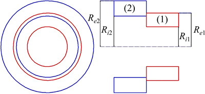
Fig. 1 Schematic illustration of shrink-fit assembly
 (15)
(15)
However, this solution is just limited to simple cylindrical parts in linear elastic state and cannot produce reliable results for most industrial cases like shrink- fitted connection of gear shaped bodies [2, 14, 20]. So, a numerical study is required for re-optimizing the parameters of the assemblies.
3 Thermal considerations
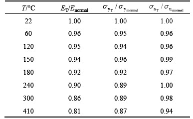
When the steel elements and structures are subjected to high temperatures, their stiffness and load carrying capacity will progressively decrease. The reduction factors of elastic modulus ET/Enormal, yieldpoint  and ultimate stress
  of high strength steel obtained from transient-state tensile test are presented in Table 1. It is noted that for given range of temperatures, the reduction factors have a maximum variation of 8%. While for temperatures greater than 500 ��C, a maximum variation of 56% was reported in Ref. [21]. So, before evaluating the distortion of gear teeth and strength of assembly, a transient thermal analysis is needed for the heated gear to predict the temperature history of the parts.
The most important part in thermal analysis is determination of the convective coefficient of heat transfer between fluid flow and external surfaces of thetwo bodies. For a wide range of Reynolds and Prandtl numbers, CHURCHILL and BERNSTEIN [22] have proposed a comprehensive and accurate equation for obtaining the convection coefficient.
Table 1 Reduction factors of yield and ultimate strength and elastic modulus of high strength steel [21]
 (16)
(16)
where is average Nusselte number; ReD is Reynolds number and Pr is Pranthle number.
When the bodies come into contact, there is heat flux across the surfaces. During the cooling phase, as the magnitude of contact pressure between the fitted gear and the shaft increases, the thermal contact resistance will sharply reduce. Knowing the variation of contact pressure with the time, the changes in thermal contact resistance in each time step of transient analysis can be readily obtained from Eq. (17) [15].
 (17)
(17)
where R is thermal resistance; P is contact pressure and A is contact area. Subsequently, the obtained results from the transient thermal analysis can then be applied as body loads in a nonlinear structural analysis for evaluating the stress and deformation fields at each time interval of structural analysis.
4 Details of finite element analysis
As an example for numerical investigation, the 3rd gear currently used in 1500-2000 mL automobiles is considered in this work. The initial diameter of the gear bore is 30 mm and the inner radius of the shaft may vary from 30.8 mm to 30.1 mm [11]. Since the maximum amount of deformation in gear teeth profile is observed for radial interference of 0.1 mm, this value is considered in this analysis. The primary specifications of modeled gear are presented in Table 2.
As shown in Fig. 2, the domain structure of gear can be divided into several sub-partitions that have equal temperature in each time interval of heat transfer. So, for each region of gear structure, the change rate of temperature and consequently, variation of temperature- dependent mechanical properties such as elastic modulus can be readily achieved.
The gear supplied with variable contact pressure on its hub has different values of stiffness in each time increment of the structural analysis. So, in each time step of investigation the corresponding value of elastic modulus should be assigned to the different regions of the gear. The obtained results in each time step are then applied as the boundary conditions for the next step of simulation.
Table 2 Thermal and mechanical properties of material at room temperature
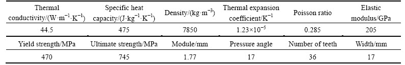
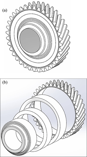
Fig. 2 Assembled structure for gear (a) and four sub-partitions considered for modeling gear structure (b)
For gear and solid shaft shown in Fig. 3, the commercial package, COSMOS, is used for numerically modeling the shrink-fit process. Since the stresses at the interface of the shrink-fitted bodies are the main concern, refined elements are used in this region. More sparse elements at the other regions of gear and shaft cause a considerable reduction computing cost of the simulation. The friction at the interface affects the radial displacement of the gear and resultant deformation of teeth profile. So, the friction is included using the elastic Coulomb friction model [23, 24]. Considering the fact that there is a little difference between the diameters of gear hub and the shaft, in practice they are modeled with the same diameter 30 mm for simplifying the thermal analysis. The same mesh used in the thermal analysis was used for the thermal-mechanical analysis with differing element types.
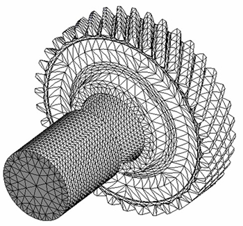
Fig. 3 Created meshes for thermal and mechanical analysis of problem (Finer mesh is adopted for contact area)
5 Results and discussion
The heating process for compensating the radial interference is analyzed through heat conduction from surface to inside of gear after generating convection between the environment with flame temperature of 1000 ��C and convection coefficient 50 W/(m2��K). For the local temperatures above 500 ��C, the material can be tempered and then softened. This softening will result in a disaster for the shrink fit strength. It is also dangerous if a longer time heating is allowed. So, the heating time and the heating method must be strictly checked and controlled. After 60 s heating time, internal radius of the gear hub is increased by 0.9 mm. The gradient of temperature induced in the gear is shown in Fig. 4. It is clear that the gear temperature does not exceed the mentioned critical value.
Just after mating the two bodies, thermal conduction between the bodies and radiation/convection heat exchange with surrounding occurs because of temperature difference. In this work, as previously stated, the shrink-fit assembly is considered a transient thermo- mechanical process. As result, the average contact pressure at the midpoint of fit-length would be a time- dependent parameter of which intensity of variation may be affected by cooling and contact conditions. For several modes of heat convection and frictioncoefficients, the results of FEM for average contact pressure are given in Figs. 5 and 6. It can be observed that for all cases the average contact pressure between the bodies sharply increases and finally converges to a specific value.
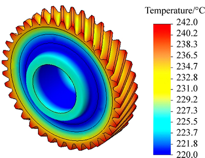
Fig. 4 Gear temperature gradient after 60 s heating process
In order to show the reliability of current simulation, distributions of stresses along the gear central line are determined by FEM and Lame��s equations. The finite element analysis is performed for friction coefficient f=0.5 and cool down rate h=5 W/(m2��K). Figure 7 showsthat the results are compatible with the results of analytical solution.
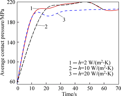
Fig. 5 Effect of heat transfer intensity on increase rate of average contact pressure
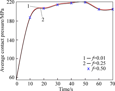
Fig. 6 Effect of friction coefficient on increase rate of average contact pressure
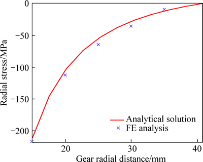
Fig. 7 Comparing results of numerical and analytical analyses for radial stress distribution along gear central line
Because of its popularity and acceptability, the obtained results from Lame��s equations are used as a criterion for assessing the validity of the other developed numerical methods. However, the Lame��s theory for the stresses analysis of shrink-fit problem is based on circular geometrical symmetry of the bodies and assuming a uniform contact pressure along the interface surface. So, the stress and strain distributions are found to be identical for each mode of heat transfer and circumferential contact condition of interface surface.
It is noted that different cooling conditions at the regions exposed to the ambient are more intense. So, the stresses may not have a uniform distribution over the contact area. On the other hand, the friction coefficient at the contact area plays an important role in amount of generated stresses inside the assembled bodies.
Distribution of tangential stress over the shaft obtained for several heat transfer rate and friction coefficient are compared in Figs. 8(a) and (b). It can be observed that the friction coefficient can be considered a contributing factor for controlling the generated stresses. Furthermore, the results FEM for stresses and their distribution are more reliable than those obtained from the traditional method. The superiority of the FEM to traditional method can be explained as follows: in Lame��s theory for thick-wall cylinders, the bodies are assumed to be in linear elastic state with uniform pressure distribution along their contact area. However, the level of radial interference may considerably affect the stresses as well as their distributions and may cause local plastic deformations. The stress distribution is also affected by the circumferential contact surface of the cylinder where it may be the most critical zone in terms of heat transfer during cooling of such interference fittings. So, the stress at the end of interference-fitted region shows trends in different characters due to different cooling conditions around circumferential contact. On the other hand, the cross-section��s shape of joined elements is another parameter that affects the distribution of stresses [23]. It can be concluded that the results of FEM-based stress of interference fitted connections, which contains all mentioned facts, are more complete and accurate than those obtained from the traditional method.
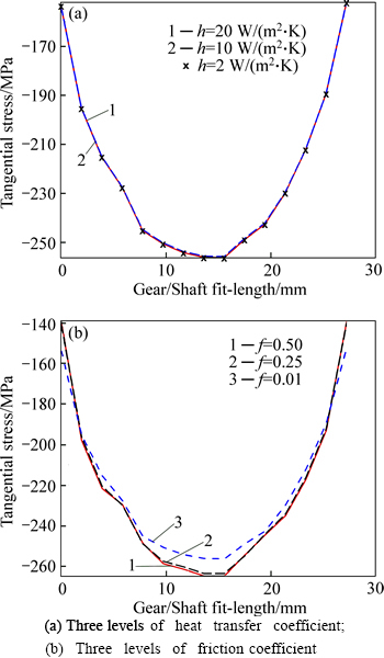
Fig. 8 Distribution of tangential stress on shaft:
The radial and tangential stress distributions at gear hub surface are shown in Figs. 9 and 10. For both gear and shaft, the radial stresses are compressive with almost identical distributions. However, the tangential stresses in the gear hub are different and with positive character. It is clear from Figs. 9(a) and 10(a) that heat transfer intensity has more serious effect on stresses distributed over internal surface of gear hub. It can be seen that important stress concentrations occur at the ends of fit-length. It is also noted that the radial stresses are lower than the tangential stresses at the end points (Figs. 10(a) and (b)).
As mentioned earlier, the radial and tangential stresses generated inside the gear body are with different compressive and tensile characters, respectively. So, the von-Mises equivalent stresses of the gear hub along fit-length are much greater than the equivalent stresses in the shaft. The gradient of von-Mises equivalent stress for three different modes of heat transfer and coefficients of friction are shown in Figs. 11 and 12. It can be found from the results that the coefficient of heat transfer has no effect on intensity of stress gradient. However, the gradients are slightly affected by higher coefficients of friction. It can also be observed that for all the cases the ends of fit-length are particularly prone to plastic deformation.
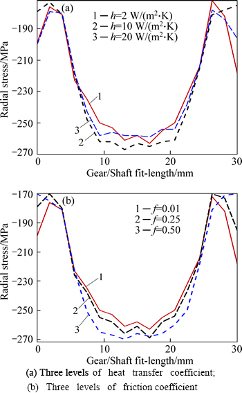
Fig. 9 Distribution of radial stress on gear hub:
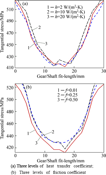
Fig. 10 Distribution of tangential stress on shaft:
According to the results of MUCHA [23], the stress field distribution is not identical for various cross- sectional shape of the jointed elements. So, FEM stressanalysis is performed for two gears with different hub lengths. Same contact and thermal conditions are held for the cases. It can be observed from Fig. 13 that a considerable increase in amount of von-Mises equivalent stress can be found for shorter hub length.
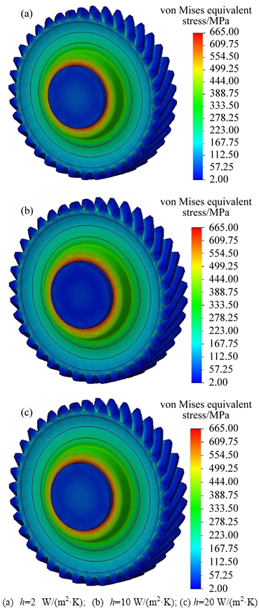
Fig. 11 Gradient of von-Mises stress for f=0.01 and three coefficients of heat transfer:
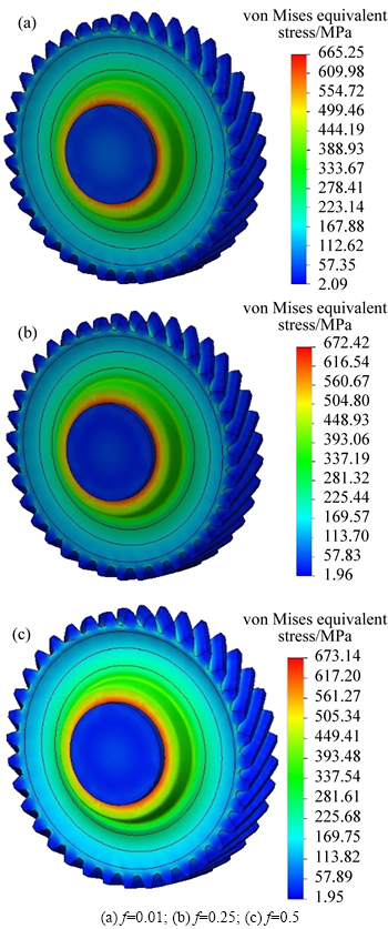
Fig. 12 Gradient of von-Mises stress for h=2 W/(m2��K) and three coefficients of friction:
The radial displacements have a great effect on radial interference between the two mating teeth. Any change in radial interference increases the pitch-line velocity and makes the gears noisier. It also causes change in pressure angle, reducing the transmitted power. The deformed configurations of teeth are compared with their initial forms in Fig. 14. The green colored bodies represent teeth of the gear after assembly.
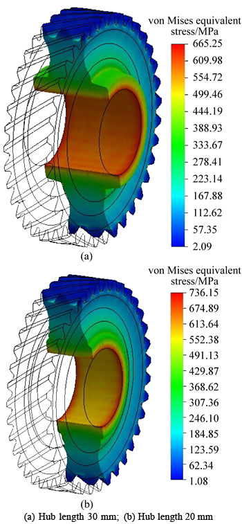
Fig. 13 Effect of hub length on gradient of generated von-Mises stress inside gear structure:
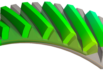
Fig. 14 Teeth of gear before and after assembly
For a specific gear, radial displacements of the points located on the top surface of gear are depicted in Fig. 15. As result, time variation of gear configuration can be schematically obtained. It can be observed that the highest rigidity of the gear at its neighboring surface is in its center. For three values of friction coefficients, variations in the maximum radial displacement along the tip of a tooth are shown in Fig. 16. It can be found that more radial displacements occur for higher values of friction coefficients on the contact area. Furthermore, for coefficients less than 0.25 there is a severe dependency between the radial displacement and friction coefficient.
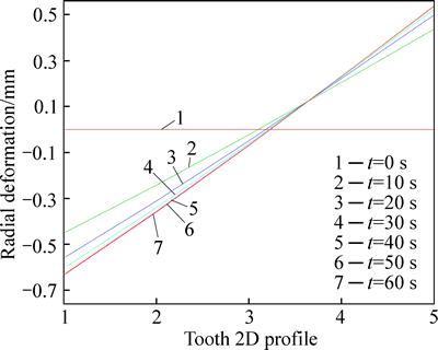
Fig. 15 Variation of a selected tooth profile with time

Fig. 16 Variation of maximum radial displacement of gear teeth with friction coefficient
The effect of heat transfer coefficient on the radial displacements of gear teeth are studied in Fig. 17. For all the cases, the friction coefficient is set to be 0.125. The results show a negligible decrease in amount of the maximum endured displacement with increasing coefficients of heat transfer. It is noted that all regions of the gear and shaft structures have sufficiently adequate exchanging surfaces with the ambient environment. So, any increase in coefficient of convectional heat transfer has rather simultaneous effects on all regions of the problem domain. MUCCHA [23] showed that the most unfavorable case exists when the temperature compensation of both bodies occurs at negligible heat losses to an ambient environment. Hence, in the real case of thermal exchanging with the environment, the coefficient of heat transfer has a negligible effect on the results.
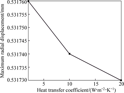
Fig. 17 Variation of maximum radial displacement of gear teeth with heat transfer coefficient
6 Conclusions
1) The FE method for analysis of shrink-fit assembly of complex-shaped elements provides more accurate results than Lame��s equations and is considered to be helpful designing tool for evaluating the strength and distortion of the joint in various cases and determining optimal assembly conditions.
2) According to the results, the friction coefficient at contact surface and the intensity of heat transfer during cooling stage, are found to be decisive parameters affecting the stress distribution generated inside the outer and inner elements.
3) In any manufacturing process, the frictional condition is recognized to be a more effective parameter than the thermal condition.
4) It is observed that the end zones are more dangerous than the central zones.
5) The hub geometry of the gear is found to be effective for decreasing the stress concentrations and displacements.
Nomenclature
f Coefficient of friction
h Coefficient of heat transfer
r Radial distance
E Elastic stress
��y Yield stress
��u Ultimate stress
��rr Radial stress
���Ȧ� Tangential stress
��r�� Shear stress
��zz Stress in z direction
��rr Radial strain
���Ȧ� Tangential strain
ur Radial displacement
�� Poisson ratio
�� Coefficient of thermal expansion
��T Temperature variation
�� Radial interference
Nu Nusselt number
Pr Prandtl number
Re Reynolds number
R Thermal resistance
A Area
hc Thermal conductance
References
[1] ZHANG L, ZHANG J, KALAOUI H, LI H, WANG Y. A comparative study of the residual deformation of an automotive gear-case assembly due to deep-penetration high-energy welding [J]. Journal of Materials Processing Technology, 2007, 190(1-3): 109-116.
[2] BOUTOUTAOU H, BOUAZIZ M, FONTAINE J F. Modelling of interference fits with taking into account surfaces roughness with homogenization technique [J]. International Journal of Mechanical Sciences, 2013, 69: 21-31.
[3] MACK W, BENGERI M. Thermal assembly of an elastic-plastic shrink fit with solid inclusion [J]. International Journal of Mechanical Sciences, 1994, 36(8): 699-705.
[4] SEN S, AKSAKAL B. Stress analysis of interference fitted shaft�Chub system under transient heat transfer conditions [J]. Materials & Design, 2004, 25(5): 407-417.
[5] EYERCIOGLU O, KUTUK M, YILMAZ N. Shrink fit design for precision gear forging dies [J]. Journal of Materials Processing Technology, 2009, 209(4): 2186-2194.
[6]  ZEL A, TEMIZ
  , AYDIN M D, EN S. Stress analysis of shrink-fitted joints for various fit forms via finite element method [J]. Materials & Design, 2005, 26(4): 281-289.
[7] ZHU C, JIN Y. The solution of frictional contact problems using a finite element-mathematical programming method [J]. Computers & Structures, 1994, 52(1): 149-155.
[8] JIA Guo-hai, GONG Jin-ke, E Jia-qiang, CAI Hao, WANG Shu-hui. Fretting instability characteristics for gear shaft shoulder [J]. Journal of Central South University, 2014, 21(10): 3746-3752.
[9] SNIEZEK L, ZIMMERMAN J, ZIMMERMAN A. The carrying capacity of conical interference-fit joints with laser reinforcement zones [J]. Journal of Materials Processing Technology, 2010, 210(6): 914-925.
[10] ZHU Z Y, SUN D Y, XU S M. Stress distribution and fatigue life of built-up sleeved backup roll [J]. Journal of Central South University of Technology, 2012, 19: 2173-2178.
[11] KIM H, KIM C, BAE W, HAN S. Development of optimization technique of warm shrink fitting process for automotive transmission parts (3D FE analysis) [J]. Journal of Materials Processing Technology, 2007, 187: 458-462.
[12] XIE J Q, AGAPIOU J S, STEPHENSON D A, HILBER P. Machining quality analysis of an engine cylinder head using finite element methods [J]. Journal of Manufacturing Processes, 2003, 5(2): 170-184.
[13] SAMANT R N, PHELAN P E, ULLAH M R. Finite element analysis of residual-stress-induced flatness deviation in banded carbon seals [J]. Finite Elements in Analysis and Design, 2002, 38(9): 785-801.
[14] ZHANG Y, MCCLAIN B, FANG X. Design of interference fits via finite element method [J]. International Journal of Mechanical Sciences, 2000, 42(9): 1835-1850.
[15] GOLBAKHSHI H, NAMJOO M, MOHAMMADI M. A 3D comprehensive finite element based simulation for best Shrink Fit design process [J]. Mechanics & Industry, 2013, 14(01): 23-30.
[16] TANG J Y, HU Z H, WU L J, CHEN S Y. Effect of static transmission error on dynamic responses of spiral bevel gears [J]. Journal of Central South University, 2013, 20: 640-647.
[17] JOHNSON K. Contact mechanics [M]. Cambridge: Cambridge University Press, 1974.
[18] UGURAL A C, FENSTER S K. Advanced strength and applied elasticity [M]. Upper Saddle River, New Jersey: Prentice Hall, 2003.
[19] BURR A H. Mechanical analysis and design [M]. North-Holland: Elsevier, 1981.
[20] KUTUK M, EYERCIOGLU O, YILDIRIM N, AKPOLAT A. Finite element analysis of a cylindrical approach for shrink-fit precision gear forging dies [J]. Proceedings of the Institution of Mechanical Engineers, Part C: Journal of Mechanical Engineering Science, 2003, 217(6): 677-685.
[21] CHEN J, YOUNG B, UY B. Behavior of high strength structural steel at elevated temperatures [J]. Journal of Structural Engineering, 2006, 132(12): 1948-1954.
[22] MORGAN V T. The overall convective heat transfer from smooth circular cylinders [J]. Advances in Heat transfer, 1975, 11: 199-264.
[23] MUCHA J. Finite element modeling and simulating of thermomechanic stress in thermocompression bondings [J]. Materials & Design, 2009, 30(4): 1174-1182.
[24] SHIGLEY J, MISCHKE C, BROWN T. Standard handbook of machine design, 2004 [M]. New York: McGraw-Hill, 580-587.
(Edited by YANG Hua)
Cite this article as: Hossein Golbakhshi, Moslem Namjoo, Farhad Khoshnam. Thermo-structural analysis on evaluating effects of friction and transient heat transfer on performance of gears in high-precision assemblies [J]. Journal of Central South University, 2017, 24(1): 71-80. DOI: 10.1007/s11771-017-3410-3.
Received date: 2015-11-24; Accepted date: 2016-03-15
Corresponding author: Moslem Namjoo, Instructor; Tel: +98-34-43347061; Fax: +98-34-43347065; E-mail: m.namjoo@ujiroft.ac.ir
Abstract: The high precision assemblies with considerable radial interference should be accompanied by heating and cooling processes. However, the mechanical properties of metals are greatly affected by thermal operations. So, for evaluating the stress distribution and distortion of teeth profiles in a gear/shaft assembly, a transient thermal analysis is necessary for finding the change in mechanical properties. The friction on the contact surface is another important parameter in interaction of the gear with the shaft. Evaluating the gear stress and deformation fields for several modes of heat transfer and friction coefficients showed that the maximum radial or tangential stresses on contact surface of the joint may have more than 8% increase by increasing friction coefficient; while the intensity of heat transfer at cooling stage has lower effect on stress distribution.
