

Electrodeposition of Fe-Ni alloy coating on ferritic stainless steel
GENG Shu-jiang(������), LI Yan-dong(���Զ�), XIANG Dong(�� ��), ZHOU Shi-gang(��ʱ��)
School of Materials and Metallurgy, Northeastern University, Shenyang 110004, China
Received 6 July 2009; accepted 30 December 2009
_____________________________________________________________________________________________________
Abstract:
Fe-Ni alloy coatings were electrodeposited on ferritic stainless steel (FSS) in solutions containing FeSO4 and NiSO4. The effects of pH, [Fe2+]/[Ni2+] (molar ratio) of electroplating solutions and cathode current density on deposition rate and surface appearances of the coatings were investigated. The results indicated that the deposition rate of the coating in solution with [Fe2+]/[Ni2+] of 0.4 slightly increased with increasing pH from 2.5 to 3.5 under the current density of 5.5 mA/cm2, and then the deposition rate of the coating in solution with pH 4.0 began to decrease. The deposition rate also slightly increased with pH up to 3.5 under higher cathode current densities of 13.5 and 27 mA/cm2. Under 13.5 mA/cm2, however, the coating deposited in solution with pH 4 was prone to crack or flake. The deposition rate increased and the surface of coatings became less smooth with increasing cathode current density. The effect of the ratio of [Fe2+] to [Ni2+] on deposition rate was not obvious. With increasing the ratio of [Fe2+] to [Ni2+] in plating solution, the content of Fe in the coatings increased; while the Ni content in the coatings decreased with the increase in the ratio of [Fe2+] to [Ni2+]. The deposited coating consisted of Fe-Ni alloy phase.
Key words:
Fe-Ni alloy; electroplating; ferritic stainless steel; coating;
_____________________________________________________________________________________________________
1 Introduction
Solid oxide fuel cells (SOFCs) are electrochemical conversion devices that produce electricity directly from oxidizing a fuel. SOFCs have a wide variety of applications from use as auxiliary power units in vehicles to stationary power generation due to advantages of SOFCs, including high efficiency, fuel flexibility and low emission[1-2]. Interconnect is a critical component of the planar SOFCs stack that separates the oxidant and fuel gases. It can be either a ceramic or metallic material between each individual cell to connect cells in series, so that the electricity generated by each cell can be combined. Because the interconnect is simultaneously exposed to both the oxidizing side and reducing side of the cell at high temperatures, it must be extremely stable. For this reason, ceramics have been more successful in the long term use than metals as interconnect materials. Nevertheless, these ceramic interconnecting materials are very expensive and difficult to process as compared with metals. Metallic materials are becoming more promising as lower temperature (600-800 ��) SOFCs have been developed[3-5]. The most common metallic materials used today are Cr2O3-forming alloys such as ferritic stainless steel (FSS) that has demonstrated to be thermally stable at high temperatures and have the ability to match the coefficient of thermal expansion (CTE) of adjacent cell/stack components[6-8]. However, the evaporation of chromia grown thermally on FSS might migrate to and poison the cathode, leading to the degradation of the SOFC stack performance. To solve this problem, different coatings have been developed[9-10]. Thermal expansion behavior of Fe-Ni alloys was similar to that of other SOFC components, and oxide scales formed on them in the environment of SOFC cathode possessed high electrical conductivity[11]. So, Fe-Ni alloy coatings are potential to solve this problem of chromia evaporation. After thermal exposure at the environment of SOFC cathode, the oxide scale of the Fe-Ni alloy coatings was expected to block Cr2O3 evaporation.
In this study, the Fe-Ni alloy coatings were electroplated on FSS in the electroplating solutions mainly consisting of NiSO4 and FeSO4. The electroplating solution parameters including pH and ratio of [Fe2+] to [Ni2+] as well as cathode current density were investigated to electroplate the Fe-Ni alloy coating on FSS.
2 Experimental
The specimens of 1.5 cm��1.0 cm��1.0 mm in size cut from the ferritic stainless steel sheet (main composition in mass fraction: 16.4% Cr, 0.28% Si, 0.13% Mn and balance Fe) were ground to 1 000 grit using SiC sand papers and then were ultrasonically cleaned in acetone, followed by rinsing at 60�� in the solution of 20% NaCO3 (mass fraction) and 10% H2SO4 (mass fraction), respectively. The clean stainless steel sample was used as cathode. Nickel sheet was used as anode. The composition of electroplating solution and the electroplating conditions are listed in Table 1.
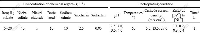
Table 1 Concentration of chemical reagents and electroplating conditions
Surface morphologies and compositions of the Fe-Ni alloy coatings were examined using scanning electron microscope with an energy dispersive X-ray analyzer (SEM/EDX). The phase structures of the coatings were identified with X-ray diffractometer (XRD).
3 Results and discussion
To study the effect of pH value of plating solution on deposition rate and surface appearance of the Fe-Ni alloy coatings, the pH of plating solution with the ratio of [Fe2+] to [Ni2+] of 0.4 was adjusted to 4.0, 3.5, 3.0 or 2.5 by adding dilute H2SO4. Fig.1 shows the deposition rate of the coating in solutions with different pH values at 60 �� under different cathode current densities. The deposition rate of the coating deposited under 5.5 mA/cm2 slightly increased with pH from 2.5 to 3.5, and then began to decrease. The deposition rate of the coating under higher cathode current densities of 13.5 and 27.0 mA/cm2 also slightly increased with increasing pH. However, the coatings deposited in solution with pH 4 began to crack or flake. As shown in Fig.2, the surface of the coating deposited in solution with pH 4 under 5.5 mA/cm2 was smooth. Nevertheless, the coating deposited in solution with pH 4 under 13.5 mA/cm2 or 27.0 mA/cm2 was cracked and peeled. This might be originated from higher pH that promoted the formation of Fe(OH)2 particles on the cathode surface. These particles embedded in the coating subsequently led to the brittlement and cracking/spallation of the coating. Considering quality and deposition rate of the coatings, the electroplating solution with pH 3.5 was chosen.
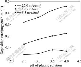
Fig.1 Deposition rate of Fe-Ni alloy coatings electroplated at 60 �� in solution with [Fe2+]/[Ni2+] of 0.4 under different pH values and different cathode current densities
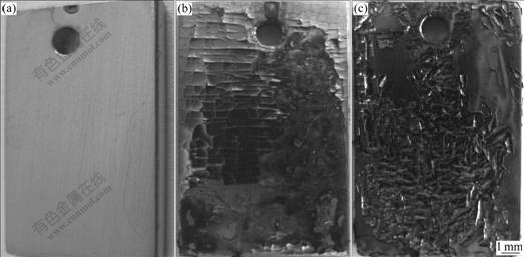
Fig.2 Surface appearances of Fe-Ni coatings deposited at 60 �� in solution with pH 4 and [Fe2+]/[Ni2+] of 0.4 under different cathode current densities: (a) 5.5 mA/cm2; (b) 13.5 mA/cm2; (c) 27.0 mA/cm2
From Fig.1, it could also be seen that the deposition rate of the coating under higher cathode current density of 13.5 or 27.0 mA/cm2 was higher than that under lower cathode current density of 5.5 mA/cm2. The electro- deposition under further high cathode current density was carried out to study the effect of cathode current density on deposition rate and surface appearances. It could be indicated from Fig.3 that the deposition rate of the coating increased with the increase in cathode current density. However, the surface of the coating deposited under 41 or 57 mA/cm2 was not as smooth as that deposited under 27 mA/cm2. As shown in Fig.4(a), the surface of the coating deposited under 27 mA/cm2 was very smooth. There were some nodules on the surface (especially on the edges of the samples) of the coatings deposited under 41 mA/cm2 (Fig.4(b)) and 57 mA/cm2 (Fig.4(c)). Although the higher cathode current densities accelerated deposition rate, the quality of the coatings became worse due to fast deposition rate. So, the cathode current density of 27 mA/cm2 was suitable for deposition.
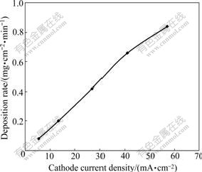
Fig.3 Deposition rates of Fe-Ni coatings deposited at 60 �� in solution with pH 3.5 and [Fe2+]/[Ni2+] of 0.4 under different cathode current densities
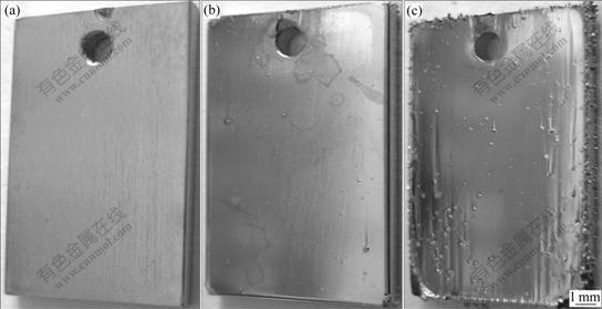
Fig.4 Surface appearances of Fe-Ni coatings deposited at 60 �� in solution with pH 3.5 and [Fe2+]/[Ni2+] of 0.4 under different cathode current densities: (a) 27 mA/cm2; (b) 41 mA/cm2; (c) 57 mA/cm2
Fig.5 shows the deposition rate of the coatings deposited in solution with different ratios of [Fe2+] to [Ni2+] and pH 3.5 under 27 mA/cm2. The deposition rate of the coating in solution with [Fe2+]/[Ni2+] of 0.1 was slightly higher than that in the solution with the ratios of [Fe2+] to [Ni2+] of 0.2, 0.3 or 0.4. No obvious differences were found in deposition rate for coatings in solutions with [Fe2+]/[Ni2+] of 0.2, 0.3 and 0.4. The appearances of the coatings deposited in solutions with different ratios of [Fe2+] to [Ni2+] are similar and smooth. The difference was that the contents of Fe in the coatings increased with increasing the ratio of [Fe2+] to [Ni2+], while Ni contents in the coatings decreased with increase in the ratio of [Fe2+] to [Ni2+]. Fig.6 shows Fe and Ni contents detected by EDX in the coatings deposited at 60 �� in pH 3.5 solution with different ratios of [Fe2+] to [Ni2+]. When the ratio of [Fe2+] to [Ni2+] was 0.4, the composition of the coating was close to Fe-60Ni (mass fraction, %) which was suitable candidate for intermediate temperature solid oxide fuel cell interconnect application among Fe-Ni alloys[11].
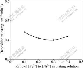
Fig.5 Deposition rate of Fe-Ni coatings at 60 �� in solution with different ratios of [Fe2+] to [Ni2+] and pH 3.5 under 27 mA/cm2
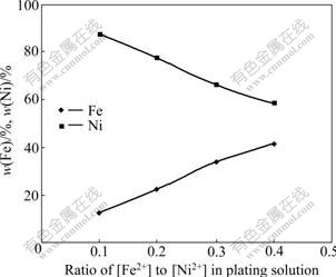
Fig.6 Fe and Ni contents of coatings deposited at 60 �� in solution with pH 3.5 and different ratios of [Fe2+] to [Ni2+] under 27 mA/cm2
Fig.7 shows the XRD patterns of the substrate and the coating deposited at 60 �� in pH 3.5 solution with[Fe2+]/[Ni2+] of 0.4. The substrate was composed of Fe-Cr alloy phase and the coating consisted of Fe-Ni alloy phase. A preferred orientations of (111) and (200) were found, which resulted from the addition of saccharin in electroplating solution[12]. The surface morphology of the coating was observed using SEM. As shown in Fig.8, the coating with composition of Fe-60Ni was very dense.
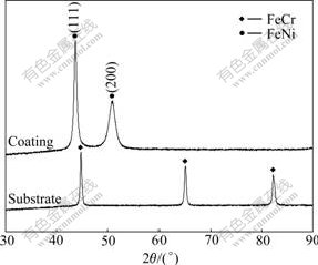
Fig.7 XRD patterns of stainless steel substrate and coating deposited at 60 �� in pH 3.5 solution with [Fe2+]/[Ni2+] of 0.4 under 27 mA/cm2
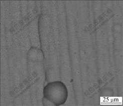
Fig.8 SEM surface morphology of coating deposited at 60 �� in pH 3.5 solution with [Fe2+]/[Ni2+] of 0.4 under 27 mA/cm2
4 Conclusions
1) Under 5.5 mA/cm2, the deposition rate slightly increased with increasing pH from 2.5 to 3.5. When the pH was 4.0, the deposition rate began to decrease. The deposition rate increased with pH increasing under higher cathode current densities of 13.5 and 27 mA/cm2. The coating deposited in solution with pH 4 under 13.5 or 27 mA/cm2 began to crack and flake.
2) The deposition rate also increased with the increase in cathode current density. However, the surface of the coatings deposited under 41 or 57 mA/cm2 appeared in nodules.
3) Under 27 mA/cm2, there were not obvious differences on deposition rate and surface appearances when the ratio of [Fe2+] to [Ni2+] in pH 3.5 solution was changed from 0.1 to 0.4. As the ratio of [Fe2+] to [Ni2+] increased, the content of Fe in the coatings also increased. The deposited coatings were composed of Fe-Ni alloy.
References
[1] KARAKOUSSIS V, BRANDON N P, LEACH M, van der VORST R. The environmental impact of manufacturing planar and tubular solid oxide fuel cells [J]. Journal of Power Sources, 2001, 101(1): 10-26.
[2] WILLIAMS M C, STRAKEY J P, SURDOVAL W A. The U.S. department of energy, office of fossil energy stationary fuel cell program [J]. Journal of Power Sources, 2005, 143(1/2): 191-196.
[3] HORITA T, XOING Y P, YAMAJI K, SAKAI N, YOKOKAWA H. Stability of Fe-Cr alloy interconnects under CH4-H2O atmosphere for SOFCs [J]. Journal of Power Sources, 2003, 118(1/2): 35-43.
[4] ZENG Z, NATESAN K. Corrosion of metallic interconnects for SOFC in fuel gases [J]. Solid State Ionics, 2004, 167(1/2): 9-16.
[5] FERGUS J W. Metallic interconnects for solid oxide fuel cells [J]. Materials Science and Engineering A, 2005, 397(1/2): 271-283.
[6] YANG Z, HARDY J S, WALKER M S, XIA G, SIMMER S P, STEVENSON J W. Structure and conductivity of thermal grown scales on ferritic Fe-Cr-Mn steel for SOFC interconnect applications [J]. Journal of the Electrochemical Society, 2004, 151(11): A1825-A1831.
[7] YANG Z, WALKER M S, SINGH P, STEVENSON J W, NORBY T. Oxidation behavior of ferritic stainless steel under SOFC interconnect exposure conditions [J]. Journal of the Electrochemical Society, 2004, 151(12): B669-B678.
[8] HAN M, PENG S, WANG L, YANG Z, CHEN X. Properties of Fe-Cr based alloys as interconnects in a solid oxide fuel cell [J]. Journal of Power Sources, 2007, 164(1): 278-283.
[9] KIM J H, SONG R H, HYUM S H. Effects of slurry-coated LaSrMnO3 on the electrical property of Fe-Cr alloy for metallic interconnect of SOFC [J]. Solid State Ionics, 2004, 174(1/4): 185-191.
[10] YANG Z, XIA G, STEVENSON J W. Mn1.5Co1.5O4 spinel protection layers on ferritic stainless steels for SOFC interconnect applications [J]. Electrochemical and Solid-State Letters, 2005, 8(3): A168-A170.
[11] ZHU J, GENG S, LU Z, PORTER W D. Evaluation of binary Fe-Ni alloys as intermediate temperature SOFC interconnect [J]. Journal of the Electrochemical Society, 2007, 154 (12): B1288-B1294.
[12] SOHN K S H, JOO H J, KIM Y C, YIM Y W, LEE H Y, KANG T. Effect of saccharin addition on the microstructure of electrodeposited Fe-36wt.%Ni alloy [J]. Surface and Coatings Technology, 2005, 199(1): 43-48.
____________________________
Foundation item: Project(12301014) supported by the National Undergraduate Innovation Program of China
Corresponding author: GENG Shu-jiang; Tel: +86-24-83673860; E-mail: gengsj@smm.neu.edu.cn
