

J. Cent. South Univ. (2020) 27: 608-620
DOI: https://doi.org/10.1007/s11771-020-4320-3

Proposal and analysis of a coupled power generation system for natural gas pressure reduction stations
LI Cheng-hao(�����), ZHENG Si-yang(֣˼��), CHEN Xing-yu(������),LI Jie(���), ZENG Zhi-yong(��־��)
School of Energy Science and Engineering, Central South University, Changsha 410083, China
 Central South University Press and Springer-Verlag GmbH Germany, part of Springer Nature 2020
Abstract:
With the increased use of natural gas, it is valuable to study energy recovery ratio in the natural gas pressure reduction stations (PRSs). This paper focused on recovering the energy in PRSs as well as low-grade waste heat by a coupled power generation system (CPGS). The CPGS integrates a natural gas expansion (NGE) subsystem and an organic Rankine cycle (ORC) subsystem driven by low-temperature waste heat. Firstly, a comparative analysis is carried out between the separated natural gas expansion system and the separated ORC system. Then, the effects of heat source conditions, upstream pressure of natural gas and the isentropic efficiency of the natural gas expander are investigated. At last, working fluids selection is conducted with respect to two different pressure ranges of natural gas. The results show that there is an optimal temperature and mass flow rate of the heat source that maximizes the system exergy efficiency. With the increase of the upstream pressure of natural gas, the net power output and waste heat recovery factor increase while the system exergy efficiency has an optimal point. Furthermore, the isentropic efficiency of the natural gas expander has a great influence on the net power output of the system.
Key words:
natural gas; energy recovery; organic Rankine cycle (ORC); working fluids selection��
Cite this article as:
LI Cheng-hao, ZHENG Si-yang, CHEN Xing-yu, LI Jie, ZENG Zhi-yong. Proposal and analysis of a coupled power generation system for natural gas pressure reduction stations [J]. Journal of Central South University, 2020, 27(2): 608-620.
DOI:https://dx.doi.org/https://doi.org/10.1007/s11771-020-4320-31 Introduction
Natural gas is a kind of clean fossil fuel, and it is extensively used for its favorable characteristics like higher calorific value, abundant reserve, extensive distribution, and nonpolluting emission [1]. The consumption of natural gas has been increasing recently and it accounts for nearly a quarter of the primary energy consumption worldwide [2]. It may become the second leading primary energy resource by 2030 [3]. The transportation of natural gas mainly has two categories. One is transported through gas pipeline; the other is transformed to liquified natural gas (LNG) and then transported by sea. The former means accounts for about 70% of the global natural gas trade [4]. For the sake of reducing operational costs and transportation losses in pipelines, natural gas is usually compressed to a high-pressure state. In actual cases, according to the transportation distance between the supply and the demand regions of natural gas, the transportation pressure of natural gas varies. For long-distance transportation (>100 km), the transportation pressure ranges in 5-10 MPa. For short-distance transportation (20- 100 km), the transportation pressure ranges in 2-5 MPa [5].
Before being fed to the terminal end users or local distribution systems, high-pressure natural gas must be depressurized in pressure reduction stations (PRSs). Hence, a large amount of energy is released during the natural gas expansion process. Developing high-efficiency systems to recover the energy during the natural gas pressure reduction process is of great significance.
There are currently three primary ways to depressurize the natural gas in PRSs, namely, pressure regulation scheme, preheating scheme, and post-heating scheme (see Figure 1) [6, 7]. The core idea of preheating scheme is that the pressure regulator is substituted by a turbo expander to recover the pressure energy of high-pressure natural gas. Similar to the pressure regulator scheme, a large temperature drop (0.15-0.20 ��C/MPa) [8] occurs during the expansion process. To avoid bad effects of the cryogenic conditions, high-pressure natural gas must be preheated to a certain temperature before expansion process, so that the depressurized gas is at the permissible safe temperature range (5-7 ��C) [9, 10]. Compared to the pressure regulator scheme, the pressure energy of the high-pressure natural gas can be retrieved by preheating scheme and thus it has become a focus of recent researches. Massive researchers have explored different methods to preheat natural gas. HOWARD et al [11] proposed adopting fuel cells to preheat the upstream natural gas and improve electricity output at the same time. KOSTOWSKI et al [12] integrated an internal combustion engine (ICE) and an ORC system into the PRS. The jacket water and the exhaust gas of ICE are used to preheat natural gas; meanwhile, the system exergy efficiency is enhanced to 52% by the ORC system and ICE. SAADAT-TARGHI et al [13] proposed to use the combustion heat of a part of upstream natural gas to preheat natural gas in an inline heater. The exhaust gas is recovered by an organic Rankine flash cycle and a thermoelectric generator. SANAYE et al [14] used a gas boiler and an engine to preheat natural gas and the extra heat and electricity are co-generated by the system. It is a novel idea to utilize renewable energy to generate the required heat for high-pressure natural gas including solar energy [15, 16] and geothermal energy [17]. For the PRSs located near the industrial regions, waste heat is also an alternative source for natural gas preheating processes [18-21].
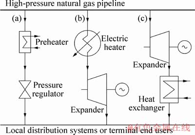
Figure 1 Schematic views of depressurization methods including pressure regulators scheme (a), preheating scheme (b) and post-heating scheme (c)
No matter the pressure regulators scheme or preheating scheme, it is necessary to consume additional energy to increase the temperature of upstream natural gas, which inevitably reduces the system efficiency. In contrast, post-heating scheme is a promising solution in which the pressure and cold energy of high-pressure natural gas are both recovered. The amended expander which can work well under the cryogenic conditions provides the possibility for the post-heating scheme [4]. The cold energy of the depressurized natural gas can be harnessed for building cooling, liquefaction of natural gas, hydrogen generation and other industrial processes requiring cold energy. Thus, the post-heating scheme provides a feasible way to improve energy utilization ratio, and it is the main focus of this paper.
Concurrently with the issue of energy recovery in PRSs, the issue of waste heat consumption has promoted novel systems design [22]. It is a huge waste that a great amount of low-grade waste heat is released to the environment by the chemical, petrochemical, power generation industries [23- 25]. There are several methods of waste heat utilization technologies [26] in which organic Rankine cycle is a good solution to recover low-temperature waste heat [27]. In this work, a coupled power generation system (CPGS) in PRSs is proposed and analyzed. The main work of the present paper includes: 1) conducting a performance comparison between the CPGS, the separated natural gas expansion system (SNGES) and the separated low-temperature ORC system (SORCS); 2) investigating the influence of the temperature and the mass flow rate of the heat source on the system performance; 3) investigating the influence of the upstream pressure of natural gas and the isentropic efficiency of the natural gas expander on the system performance; 4) selecting the suitable working fluids for the ORC system under different pressure ranges of natural gas stations.
2 System description
Figure 2 depicts the schematic presentation of the CPGS, which consists of an ORC system, a natural gas expansion system. The ORC system utilizes low-temperature waste heat as the heat source and the cold energy of the expanded natural gas as the heat sink. The turbine and the natural gas expander generate electricity for local natural gas pressure reduction stations or power consumers nearby.
The T-s diagram of the CPGS is illustrated in Figure 3. For the ORC system, the working fluid is heated by the low-temperature waste heat and boiled in the evaporator (process 2-4); then it expands in the turbine and electricity is generated (process 4-5). The exhaust gas enters the condenser and is cooled by the expanded natural gas (process 5-1). The cooled working fluid is then pressurized by the pump (process 1-2) and the process recommences. Low-temperature waste heat is massive and excessive in the modern industries including chemical, petrochemical and power generation industries, etc. The heat source first exchanges heat with the working fluid in the evaporator and then is released to the environment (process 6-7). Natural gas from the high-pressure pipeline depressurizes in the natural gas expander and the mechanical work is obtained (process N1-N2). Also, due to the adiabatic expansion effect, natural gas is cooled in the outlet of the expander. Then the cooled natural gas enters the condenser where it is heated to the room temperature by the exhaust gas from the turbine (process N2-N3). Finally, natural gas is fed to the next stage pressure reduction stations (PRSs) or the terminal end users.
3 Mathematical modeling
3.1 System assumption
The energy and exergy analysis of the CPGS is carried out in this study. The analysis is based on the first and second laws of thermodynamics. For the simplicity of the mathematical model, some assumptions have been made as follows:
1) The system is working in a steady state.
2) Pressure drops in the heat exchangers and pipes in the system are negligible.
3) All the working fluids in the ORC system are evaporated to the saturated vapor state and condensed to the saturated liquid state.
4) Natural gas is regarded as pure methane.
3.2 Energy analysis
The mass and energy conservation are applied to the energy analysis. The detailed mathematical models of system components are listed in Table 1.
3.3 Exergy analysis
Exergy analysis facilitates us to assess the available energy losses for a complex system. Exergy is a useful definition which evaluates the available part of the energy or quality of energy. The exergy of a process stream consists of four main parts: chemical exergy, physical exergy, potential exergy, and kinetic exergy[28]. Since the height and the velocity of a process stream are neglected and the combustion is not involved in this system, the chemical exergy, kinetic exergy, and potential exergy of a process stream are out of the consideration. Only the physical exergy participates in the exergy analysis and it evaluates the maximum possible work when the temperature and the pressure of the system reach an equilibrium state with the environment. The specific exergy of a process stream is defined as follows:
 (1)
(1)
and the exergy flow is calculated as the product of the mass flow rate and the specific exergy which is defined as follows:
 (2)
(2)
In order to reflect the thermodynamic perfection of the CPGS, the exergy losses of each system components are calculated. The detailed calculating equations of exergy losses are listed in Table 2.
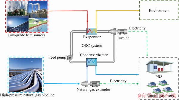
Figure 2 Schematic presentation of CPGS
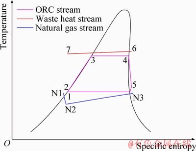
Figure 3 T-s diagram of CPGS
Table 1 Calculation equations for energy analysis of CPGS
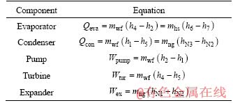
Table 2 Calculation equations for exergy losses of each system components

3.4 System indicators
Defining appropriate system indicators to assess system performance is essential to system analysis. The defined objective indexes must take crucial system aspects into consideration. In this study, to comprehensively evaluate the energy utilization ratio of the coupled system, net power output, waste heat recovery factor and system exergy efficiency are selected as the system indicators. Net power output reflects the power supply capacity of the system, waste heat recovery factor shows the low-temperature consumption ability of the system. System exergy efficiency is a comprehensive indicator that it considers the energy utilization ratio of both the natural gas expansion system and the ORC system. The definitions of the above indicators are shown as follows.
 (3)
(3)
 (4)
(4)
 (5)
(5)
3.5 Calculation parameters
The composition of natural gas has a difference when its origin differs. In this study, to make the results universal, natural gas is regarded as pure methane. The Peng-Robinson equation of states is applied to calculate the thermodynamic properties of the process streams. An optimization program based on a genetic algorithm is developed in the optimization calculation in Sections 4.1 and 4.3.
4 Results and discussion
4.1 Comparative analysis between CPGS and separated ORC system and separated natural gas expansion system
The CPGS integrates low-temperature ORC systems and natural gas expansion systems. Hence, the system makes joint use of the low-temperature waste heat and the cold energy of natural gas during the expansion process. To determine the thermodynamic performance of the CPGS compared to the separated low-temperature ORC systems (SORCS) and the separated natural gas expansion systems (SNGES), a comparative analysis has been carried out. The SNGES employs preheating scheme, in which an electric heater is employed for preheating and a natural gas expander is included. The SORCS utilizes low-temperature waste heat as the heat source and the cooling water as the heat sink. Three systems are working under a specific pressure condition: the natural gas upstream pressure is 4 MPa and the downstream pressure is 2 MPa; the upstream and the downstream temperatures of natural gas are 283 K. This pressure range is close to the pressure condition of general city gate stations. The temperature range of the low-temperature waste heat is from 323 K to 373 K, and water is regarded as the heat carrier of the waste heat. Other system parameters are optimized to maximize the system exergy efficiency. The given conditions and the optimized system parameters (in bold) are listed in Table 3.
The results of the comparative analysis are shown in Figure 4. The results show that the SORCS could make use of waste heat and the waste heat recovery factor reaches 74.41%. The net power output (18.57 kW) and the system exergy efficiency (34.19%), however, are relatively low. This is because the temperature range of the cooling water limits the enthalpy difference in the turbine of the ORC system. The SNGES obtains a lower power output (4.87 kW) as well as the system exergy efficiency (37.37%) compared to other systems. This is because the electric heater consumes a great amount of the power generated by the natural gas expander to preheat the natural gas. Meanwhile, the preheating process causes large exergy destruction which makes a low system exergy efficiency. As can be observed in Table 3, the heating efficiency of the electric heater is 0.7 which is close to the parameter of general small-scale gas heaters. For some large-scale gas heaters, this parameter may decrease, and the net power output will below zero, which means that the SNGES needs additional energy input. The CPGS has a better system performance including net power output (76.73 kW), system exergy efficiency (68.55%) and waste heat recovery factor (90.03%). This is because the coupled system not only utilizes the pressure energy of the upstream natural gas but also uses the cold energy of natural gas to increase the enthalpy difference in the turbine of the ORC system. It is seen in Table 3 that the heat source temperature of CPGS is 323 K. If the temperature increases, the net power output will further increase and the system exergy efficiency may to some extent decrease. Hence, the coupled system improves the power generation capacity during the natural gas expansion process as well as the waste heat consumption ability.
Table 3 Given conditions and optimized system parameters (in bold) of comparative analysis
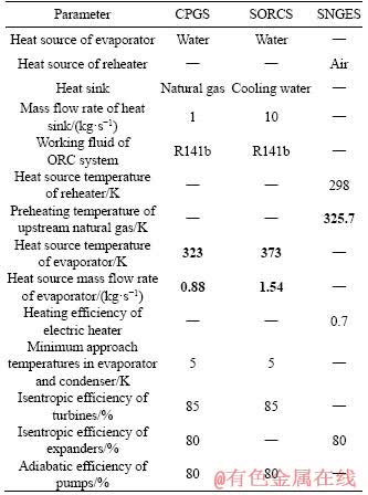
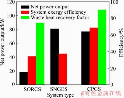
Figure 4 Results of comparative analysis
4.2 Parametric analysis
Parametric analysis is a useful tool to determine the influence of the parameters to the system performance. It provides guidance and directions for system designs and optimizations. In the present work, the influences of heat source conditions, upstream pressure of natural gas and isentropic efficiency of the natural gas expander on system performance are investigated.
4.2.1 Effects of heat source conditions
Due to the different types of industries nearby the natural gas pressure reduction stations, the heat source conditions including temperature and mass flow rate have a variant. For the conventional power generation industry, the temperature of cooling water is generally below 373 K. For the combined power and heat system, the temperature of waste heat usually ranges from 323 K to 393 K. The waste heat mass flow rate varies with different scales of the industrial plants. Hence, it is significant to investigate the effects of heat source conditions on system performance. In this section, the upstream pressure of natural gas and isentropic efficiency of the natural gas expander are kept constant, which are 4 MPa and 80%, respectively. The temperature range of heat source is from 323 K to 373 K, and the heat source mass flow rate varies from 1.0 kg/s to 2.0 kg/s.
Figure 5 shows the 3D contour of net power output with the simultaneous variations of the temperature and the mass flow rate of the heat source. It is seen that keeping the heat source temperature constant and increasing the heat source mass flow rate only, the net power output slightly increases. Keeping the heat source mass flow rate constant and increasing heat source temperature only, the net power output increases dramatically. This is because increasing the heat source temperature leads to the increase of the enthalpy difference in the turbine. The power output of the turbine equals the product of the mass flow rate of working fluid and the enthalpy difference in the turbine. Hence, under the same mass flow rate of the working fluid, increasing heat source temperature improves the power output of the turbine as well as the net power output of the system. To reveal the relation of the heat source mass flow rate and the net power output, Figure 6 shows the T-Q diagram of the evaporator with different mass flow rates of the heat source. Due to the minimum approach temperature in the evaporator fixing at 5 K, increasing the heat source mass flow rate leads to a higher evaporation temperature, and further increases the enthalpy difference in the turbine, which improves the net power output.
Figure 7 shows the 3D contour of waste heat recovery factor with the simultaneous variations of the temperature and the mass flow rate of the heat source. It can be observed that decreasing the heat source temperature and mass flow rate can both increase the waste heat recovery factor. This can be explained as follows. The definition of the waste heat recovery factor (i.e. Eq. (4)) can be rewritten into the following form:
 (6)
(6)
When the heat source temperature is constant, the specific inlet exergy of heat source is fixed as well, decreasing the heat source mass flow rate could result in the decrease of the outlet exergy of the heat source (see Figure 6). As a result, the waste heat recovery factor increases with the decrease of the heat source mass flow rate. When the heat source mass flow rate is constant, decreasing the heat source temperature leads to the decrease of both the inlet and the outlet exergy of the heat source. The outlet condition of the heat source approaches the environment state and the outlet exergy moves closer to zero so that the ratio of the outlet exergy and the inlet exergy is also close to zero. The waste heat recovery factor increases with the decrease of the heat source temperature.
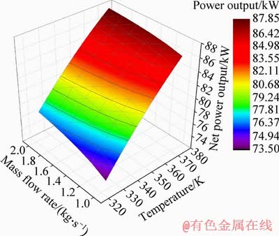
Figure 5 3D contour of net power output with simultaneous variations of temperature and mass flow rate of heat source
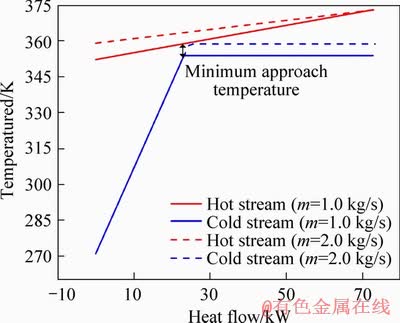
Figure 6 T-Q diagram of evaporator with different mass flow rates of heat source
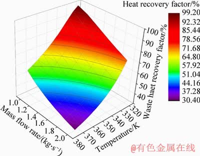
Figure 7 3D contour of waste heat recovery factor with simultaneous variations of temperature and mass flow rate of heat source
Figure 8 shows the 3D contour of system exergy efficiency with the simultaneous variations of the temperature and the mass flow rate of the heat source. It is seen that, with the decrease of the heat source temperature, the system exergy efficiency increases. When the heat source mass flow rate is relatively low, the system exergy efficiency first increases and then decreases and an optimal point exists. With the decrease of the heat source mass flow rate, the system exergy efficiency increases. When the heat source temperature is relatively low, the system exergy efficiency changes slightly. This is because that, according to the definition of the system exergy efficiency (i.e.Eq. (5)), the system exergy efficiency is affected by the exergy losses in the evaporator, condenser, turbine, pump and the expander. In the case of considering the variation of the heat source conditions, the exergy loss in the evaporator mainly affects the system exergy efficiency. When the heat source temperature decreases, the exergy loss in the evaporator decreases, which leads to the increase of the system exergy efficiency. Moreover, when the heat source mass flow rate is relatively low, the magnitude of exergy loss in the evaporator is to some extent reduced so that the effect of exergy change in the evaporator is less obvious. Hence, with the decrease of the heat source temperature, the exergy loss in the evaporator decreases and exergy losses in pump and turbine increase, and the system exergy efficiency first increases then decreases and an optimal point exists. Similarly, with the decrease of the heat source mass flow rate, the exergy loss in the evaporator decreases, which results in the increase of the system exergy efficiency. When the heat source temperature is relatively low, the effect of the exergy change in the evaporator is reduced and the system exergy efficiency changes slightly.
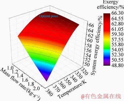
Figure 8 3D contour of system exergy efficiency with simultaneous variations of temperature and mass flow rate of heat source
4.2.2 Effect of upstream pressure of natural gas
Considering the different transportation distance of natural gas, the upstream pressure of PRSs differs. Therefore, determining the effect of the upstream pressure of natural gas is of importance for system design. In the present section, the heat source conditions are certain, the heat source temperature is 373 K and the mass flow rate is 2 kg/s. The upstream pressure of natural gas varies from 4 MPa to 10 MPa.
Figure 9 shows the variations of system performance including (a) net power output, (b) waste heat recovery factor, (c) system exergy efficiency with the variation of the upstream pressure of natural gas. It is seen from Figure 9(a) that the net power output increases monotonously with the increase of the upstream pressure of natural gas. In addition, the increasing rate of the net power output decreases with the increase of the upstream pressure of natural gas. This is because the power output of the natural gas expander increases. Meanwhile, the working fluid mass flow rate of the ORC system increases, which leads to the increase of the power output of the turbine as well. The net power output, hence, increases with the increase of the upstream pressure of natural gas. Moreover, the enthalpy change of natural gas under the cryogenic condition decreases, which makes the increment of the power output of the expander decreases while the net power output decreases as well. It is seen from Figure 9(b) that the waste heat recovery factor increases with the upstream pressure of natural gas. This is because the working fluid mass flow rate of the ORC system increases with the increase of the upstream pressure of natural gas, which leads to the decrease of the outlet exergy of heat source so that the waste heat recovery factor increases. It is seen from Figure 9(c) that the system exergy efficiency first increases and then decreases. An optimal point occurs when the upstream pressure is around 6.8 MPa. The explanation of this phenomenon is as follows. As the upstream pressure of natural gas increases, the supply exergy of natural gas in the denominator of Eq. (5) increases. Meanwhile, the exergy losses in the condenser, expander, and the turbine increase, which results in the increase of the numerator of Eq. (5). When the upstream pressure of natural gas is relatively low, the increment of the supply exergy of natural gas dominates so that the system exergy efficiency increases. Then, the increments of the exergy losses in the system components are dominant so that the system exergy efficiency reaches an optimal point and then decreases.

Figure 9 Variations of system performance including net power output (a), waste heat recovery factor (b) and system exergy efficiency (c) with variation of upstream pressure of natural gas
4.2.3 Effect of isentropic efficiency of natural gas expander
The cryogenic expander is the key component of the CPGS. Many scholars have concentrated on the design and optimization of the expander that could work efficiently under the cryogenic conditions [4, 6]. Isentropic efficiency evaluates the realistic power generation ability compared with the idealistic power generation ability. In this section, the effect of the isentropic efficiency of the natural gas expander on system performance is investigated. The heat source temperature and mass flow rate are 373 K and 2 kg/s and are kept constant. The upstream pressure of natural gas is fixed at 4 MPa.
Figure 10 presents the variation of the power output with the change of the isentropic efficiency of the natural gas expander. It is seen that the net power outputs of the expander and the turbine increase linearly with the increase of the isentropic efficiency of the natural gas expander. This makes the net power output of the system increase as well. When the isentropic efficiency increases by 5%, the net power output increases by about 7.17%. This is because, as the isentropic efficiency of the natural gas expander increases, on one hand, the power output of the expander increases; on the other hand, the outlet temperature of the expander decreases, which makes the working fluid mass flow rate of the ORC system increase and further increases the power output of the turbine.
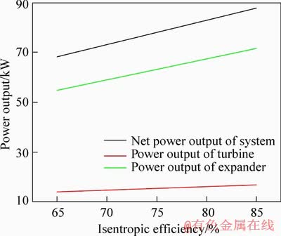
Figure 10 Variations of power output with change of isentropic efficiency of natural gas expander
4.3 Working fluids selection
Working fluids selection is of significance in organic Rankine system analysis. In CPGS, different working fluids may exert influence on system performance. Hence, this section focuses on the selection of the working fluids for the ORC system. The following criteria should be taken into consideration to choose the suitable working fluids for CPGS.
1) The system exergy efficiency should be as large as possible.
2) The net power output of the system should be as large as possible.
3) The expansion ratio of the turbine should be as small as possible.
4) The GWP value and ODP value should be near zero.
In CPGS, the working conditions do not like conventional ORC systems. Firstly, the critical temperature should be higher than 373 K to ensure the system working in the sub-critical state. Secondly, to avoid the solidification of working fluids, the triple point temperature of the selected working fluids should be lower than 193 K. Meanwhile, considering chemical stability and economic reasons, 14 kinds of working fluids and their thermophysical properties, environmental data are listed in Table 4. In this section, in order to choose the suitable working fluids for different types of natural gas pressure reduction stations, two pressure ranges of natural gas are considered. One is from 4 MPa to 2 MPa and the other one is from 10 MPa to 2 MPa. The mass flow rate and the temperature of heat source are fixed at 2 kg/s and 373 K. The outlet temperature of natural gas in the condenser (i.e. TN3) is optimized in terms of maximizing the net power output. To better determine the suitable working fluids for the CPGS, the results of working fluids selection are shown graphically in Figures 11 and 12. The system exergy efficiency versus the net power output in the pressure range of natural gas of 4-2 MPa and 10-4 MPa is shown in Figure 11. The system exergy efficiency versus the expansion ratio of the turbine in the pressure range of natural gas of 4-2 MPa and 10-4 MPa is shown in Figure 12.
Table 4 Thermophysical properties and environmental data of candidate working fluids
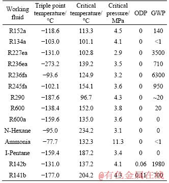
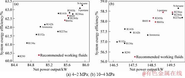
Figure 11 System exergy efficiency versus net power output for selected working fluids in pressure range of natural gas:
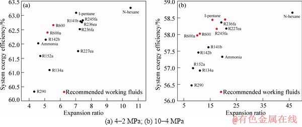
Figure 12 System exergy efficiency versus expansion ratio of turbine for selected working fluids in pressure range of natural gas:
It can be observed from Figures 11 and 12 that N-hexane has the highest system exergy efficiency and net power output in both two pressure ranges. Whereas, it has the largest expansion ratio of the turbine. It is difficult to determine the best working fluids for the coupled system. So, here we highlight the recommended working fluids on the basis of the higher system exergy efficiency and net power output and not too large expansion ratio of the expander. For the pressure range of 4-2 MPa, two working fluids including R600, R600a are selected as the better fluids for the CPGS. For the pressure range of 10-4 MPa, five working fluids including I-pentane, R236ea, R245fa, R600, and R600a are considered the suitable fluids for the CPGS. It is worth mentioning that R236fa and R227ea are out of the selected candidates because of the large GWP value while N-hexane is out of the selection for the large expansion ratio.
5 Conclusions
In this paper, in order to improve the energy recovery ratio of the natural gas depressurization process as well as the low-grade waste heat, a power generation natural gas pressure reduction station coupling with low-temperature ORC systems is proposed and analyzed by computer simulations. The main conclusions can be drawn as follows.
1) Compared with the separated natural gas expansion system (SNGES) and the separated low-temperature ORC system (SORCS), the system performance of the coupled system is improved. The CPGS makes higher power output than the SNGES or the SORCS. The CPGS also obtains higher system exergy efficiency. At the same time, the CPGS recovers more waste heat than the SORCS.
2) There is an optimal system exergy efficiency under different heat source conditions. And higher heat source temperature results in higher net power output of the system.
3) With the increase of the upstream pressure of natural gas, the net power output and the waste heat recovery factor increase, and an optimal system exergy efficiency is gained. Moreover, the isentropic efficiency of the natural gas expander exerts great importance on the net power output. When the increment of isentropic efficiency is 5%, the net power output increases by 7.17%.
4) Working fluids selection has been done in terms of the two different pressure ranges of natural gas (i.e. 4-2 MPa and 10-2 MPa). Considering the criteria of system exergy efficiency, net power output, and the expansion ratio of the natural gas expander, two suitable working fluids are selected for the pressure range of 4-2 MPa, and five working fluids for the pressure range of 10-2 MPa.
Nomenclature
Symbol
Q
Heat duty, kW
W
Power output or consumption, kW
m
Mass flow rate, kg/s
h
Enthalpy, kJ/kg
h0
Enthalpy at the environment state, kJ/kg
T0
Ambient temperature, K
s
Entropy, kJ/(kg��K)
s0
Entropy at the environment state, kJ/(kg��K)
e
Specific exergy, kJ/kg
E
Exergy, kW
El
Exergy loss, kW
Wnet
The net power output of the system, kW
Fr
Waste heat recovery factor
��ex
System exergy efficiency
Subscript
1-7, N1-N4
State points in the cycle
eva, con, pump, tur, ex
Evaporator, condenser, pump, turbine, natural gas expander, respectively
hs
Heat source
wf
Working fluid
ng
Natural gas
Abbreviation
LNG
Liquified natural gas
PRS
Pressure reduction station
ORC
Organic Rankine cycle
CPGS
Coupled power generation system
SORCS
Separated organic Rankine cycle system
SNGES
Separated natural gas expansion system
ICE
Internal combustion engine
GWP
Global warming potential
ODT
Ozone depression potential
References
[1] LO CASCIO E, BORELLI D, DEVIA F, SCHENONE C. Key performance indicators for integrated natural gas pressure reduction stations with energy recovery [J]. Energy Conversion and Management, 2018, 164: 219-229. DOI: 10.1016/j.enconman.2018.02.089.
[2] LI C H, LIU J W, ZHENG S Y, CHEN X Y, LI J, ZENG Z Y. Performance analysis of an improved power generation system utilizing the cold energy of LNG and solar energy [J]. Applied Thermal Engineering, 2019, 159: 113937. DOI: 10.1016/j.applthermaleng.2019. 113937.
[3] LI P C, LI J, PEI G, MUNIR A, JI J. A cascade organic Rankine cycle power generation system using hybrid solar energy and liquefied natural gas [J]. Solar Energy, 2016, 127: 136-146. DOI: 10.1016/j.solener.2016.01.029.
[4] YAO S, ZHANG Y F, DENG N, YU X H, DONG S M. Performance research on a power generation system using twin-screw expanders for energy recovery at natural gas pressure reduction stations under off-design conditions [J]. Applied Energy, 2019, 236: 1218-1230. DOI: 10.1016/j.apenergy.2018.12.039.
[5] TAN H B, ZHAO Q X, SUN N N, LI Y Z. Proposal and design of a natural gas liquefaction process recovering the energy obtained from the pressure reducing stations of high-pressure pipelines [J]. Cryogenics, 2016, 80: 82-90. DOI: 10.1016/ j.cryogenics.2016.09.010.
[6] FARZANEH GORD M, JANNATABADI M. Simulation of single acting natural gas Reciprocating Expansion Engine based on ideal gas model [J]. Journal of Natural Gas Science and Engineering, 2014, 21: 669-679. DOI: 10.1016/j.jngse. 2014.09.031.
[7] ASHOURI E, VEYSI F, SHOJAEIZADEH E, ASADI M. The minimum gas temperature at the inlet of regulators in natural gas pressure reduction stations (CGS) for energy saving in water bath heaters [J]. Journal of Natural Gas Science and Engineering, 2014, 21: 230-240. DOI: 10.1016/j.jngse.2014. 08.005.
[8] OLFATI M, BAHIRAEI M, HEIDARI S, VEYSI F. A comprehensive analysis of energy and exergy characteristics for a natural gas city gate station considering seasonal variations [J]. Energy, 2018, 155: 721-733. DOI: 10.1016/ j.energy.2018.05.069.
[9] POZIVIL J. Use of expansion turbines in natural gas pressure reduction stations [J]. Acta Montanistica Slovaca, 2004, 9(3): 258-260.
[10] NESELI M A, OZGENER O, OZGENER L. Energy and exergy analysis of electricity generation from natural gas pressure reducing stations [J]. Energy Conversion and Management, 2015, 93: 109-120. DOI: 10.1016/j.enconman. 2015.01.011.
[11] HOWARD C, OOSTHUIZEN P, PEPPLEY B. An investigation of the performance of a hybrid turboexpander- fuel cell system for power recovery at natural gas pressure reduction stations [J]. Applied Thermal Engineering, 2011, 31(13): 2165-2170. DOI: 10.1016/j.applthermaleng.2011. 04.023.
[12] KOSTOWSKI W J, USON S. Comparative evaluation of a natural gas expansion plant integrated with an IC engine and an organic Rankine cycle [J]. Energy Conversion and Management, 2013, 75: 509-516. DOI: 10.1016/j.enconman. 2013.06.041.
[13] SAADAT-TARGHI M, KHANMOHAMMADI S. Energy and exergy analysis and multi-criteria optimization of an integrated city gate station with organic Rankine flash cycle and thermoelectric generator [J]. Applied Thermal Engineering, 2019, 149: 312-324. DOI: 10.1016/ j.applthermaleng.2018.12.079.
[14] SANAYE S, MOHAMMADI NASAB A. Modeling and optimizing a CHP system for natural gas pressure reduction plant [J]. Energy, 2012, 40(1): 358-369. DOI: 10.1016/ j.energy.2012.01.060.
[15] FARZANEH-GORD M, ARABKOOHSAR A, DASHT- BAYAZ M D, FARZANEH-KORD V. Feasibility of accompanying uncontrolled linear heater with solar system innatural gas pressure drop stations [J]. Energy, 2012, 41(1): 420-428. DOI: 10.1016/j.energy.2012.02.058.
[16] CASCIO E L, MA Z, SCHENONE C. Performance assessment of a novel natural gas pressure reduction station equipped with parabolic trough solar collectors [J]. Renewable Energy, 2018, 128: 177-187. DOI: 10.1016/ j.renene.2018.05.058.
[17] FARZANEH-GORD M, GHEZELBASH R, ARABKOOHSAR A, PILEVARI L, MACHADO L, KOURY R N N. Employing geothermal heat exchanger in natural gas pressure drop station in order to decrease fuel consumption [J]. Energy, 2015, 83: 164-176. DOI: 10.1016/j.energy.2015.02.093.
[18] ARABKOOHSAR A, GHARAHCHOMAGHLOO Z, FARZANEH-GORD M, KOURY R N N, DEYMI- DASHTEBAYA M. An energetic and economic analysis of power productive gas expansion stations for employing combined heat and power [J]. Energy, 2017, 133: 737-748. DOI: 10.1016/j.energy.2017.05.163.
[19] BORELLI D, DEVIA F, LO CASCIO E, SCHENONE C. Energy recovery from natural gas pressure reduction stations: Integration with low temperature heat sources [J]. Energy Conversion and Management, 2018, 159: 274-283. DOI: 10.1016/j.enconman.2017.12.084.
[20] ALPARSLAN NESELI M, OZGENER O, OZGENER L. Thermo-mechanical exergy analysis of Marmara Eregli natural gas pressure reduction station (PRS): An application [J]. Renewable and Sustainable Energy Reviews, 2017, 77: 80-88. DOI: 10.1016/j.rser.2017.03.133.
[21] KOSTOWSKI W J, USON S. Thermoeconomic assessment of a natural gas expansion system integrated with a co-generation unit [J]. Applied Energy, 2013, 101: 58-66. DOI: 10.1016/j.apenergy.2012.04.002.
[22] CUI P Z, YU M X, LIU Z Q, ZHU Z Y, YANG S. Energy, exergy, and economic (3E) analyses and multi-objective optimization of a cascade absorption refrigeration system for low-grade waste heat recovery [J]. Energy Conversion and Management, 2019, 184: 249-261. DOI: 10.1016/j.enconman.2019.01.047.
[23] YU H, GUNDERSEN T, FENG X. Process integration of organic Rankine cycle (ORC) and heat pump for low temperature waste heat recovery [J]. Energy, 2018, 160: 330-340. DOI: 10.1016/j.energy.2018.07.028.
[24] MONDEJAR M E, AHLGREN F, THERN M, GENRUP M. Quasi-steady state simulation of an organic Rankine cycle for waste heat recovery in a passenger vessel [J]. Applied Energy, 2017, 185: 1324-1335. DOI: 10.1016/j.apenergy. 2016.03.024.
[25] KHALILZADEH S, HOSSEIN NEZHAD A. Utilization of waste heat of a high-capacity wind turbine in multi effect distillation desalination: Energy, exergy and thermoeconomic analysis [J]. Desalination, 2018, 439: 119-137. DOI: 10.1016/j.desal.2018.04.010.
[26] YANG S, YANG S Y, WANG Y F, QIAN Y. Low grade waste heat recovery with a novel cascade absorption heat transformer [J]. Energy, 2017, 130: 461-472. DOI: 10.1016/ j.energy. 2017.04.117.
[27] UUSITALO A, HONKATUKIA J, TURUNEN-SAARESTI T, LARJOLA J. A thermodynamic analysis of waste heat recovery from reciprocating engine power plants by means of organic Rankine cycles [J]. Applied Thermal Engineering, 2014, 70(1): 33-41. DOI: 10.1016/ j.applthermaleng.2014.04.073.
[28] LI C H, ZHENG S Y, LI J, ZENG Z Y. Optimal design and thermo-economic analysis of an integrated power generation system in natural gas pressure reduction stations[J]. Energy Conversion and Management, 2019, 200: 112079. DOI:10. 1016/j.enconman.2019.112079.
(Edited by YANG Hua)
���ĵ���
һ��������Ȼ����ѹվ�����ʽ����ϵͳ����������
ժҪ��������Ȼ�����������ӣ������Ȼ����ѹվ���������������ڱ��С�����ͨ��һ�����ʽ����ϵͳ(CPGS)�����ս�ѹվ�������Լ���Ʒλ���ȡ�CPGS��������Ȼ��������ϵͳ�͵��·����������л��ʿ�ѭ����ϵͳ�����ȣ���CPGS���������Ȼ������ϵͳ��ORCϵͳ���бȽϷ�������Σ�̽������Դ��������Ȼ������ѹ�������ͻ�����Ч�ʵ����ص�Ӱ�죻�����������ֲ�ͬ��ѹ����Χ���й���ѡ����������ڲ�ͬ����Դ�¶Ⱥ������£�ϵͳ����Ч�ʴ�������ֵ������������Ȼ��ѹ�������ӣ�ϵͳ��������ͷ������������ӣ���ϵͳ����Ч�ʴ������ŵ㡣���⣬��Ȼ�����ͻ��ĵ���Ч�ʶ�ϵͳ�����������Ӱ�졣
�ؼ��ʣ���Ȼ�����������գ��л��ʿ�ѭ��������ѡ��
Foundation item: Project(21506257) supported by the National Natural Science Foundation of China; Project(2019zzts535) supported by the Fundamental Research Funds for the Central Universities, China
Received date: 2019-05-15; Accepted date: 2019-09-02
Corresponding author: ZENG Zhi-yong, PhD, Associate Professor; Tel: +86-731-88879863; E-mail: zengzhiyong@csu.edu.cn; ORCID: 0000-0001-7569-2847
Abstract: With the increased use of natural gas, it is valuable to study energy recovery ratio in the natural gas pressure reduction stations (PRSs). This paper focused on recovering the energy in PRSs as well as low-grade waste heat by a coupled power generation system (CPGS). The CPGS integrates a natural gas expansion (NGE) subsystem and an organic Rankine cycle (ORC) subsystem driven by low-temperature waste heat. Firstly, a comparative analysis is carried out between the separated natural gas expansion system and the separated ORC system. Then, the effects of heat source conditions, upstream pressure of natural gas and the isentropic efficiency of the natural gas expander are investigated. At last, working fluids selection is conducted with respect to two different pressure ranges of natural gas. The results show that there is an optimal temperature and mass flow rate of the heat source that maximizes the system exergy efficiency. With the increase of the upstream pressure of natural gas, the net power output and waste heat recovery factor increase while the system exergy efficiency has an optimal point. Furthermore, the isentropic efficiency of the natural gas expander has a great influence on the net power output of the system.
