
Trans. Nonferrous Met. Soc. China 27(2017) 2521-2528
Cu-Al interfacial compounds and formation mechanism of copper cladding aluminum composites
Di CHU1, Jian-yu ZHANG2, Jin-jin YAO1, Yan-qiu HAN1, Chun-jing WU1
1. School of Materials Science and Engineering, University of Science and Technology Beijing, Beijing 100083, China;
2. School of Mechanical and Electrical Engineering, Hebei University of Engineering, Handan 056038, China
Received 8 August 2016; accepted 25 May 2017
Abstract:
Copper cladding aluminum (CCA) rods with the section dimensions of 12 mm in diameter and 2 mm in sheath thickness were fabricated by vertical core-filling continuous casting (VCFC) technology. The kinds and morphology of interfacial intermetallic compounds (IMCs) were investigated by SEM, XRD and TEM. The results showed that the interfacial structure of Cu/Al was mainly composed of layered ��1(Cu9Al4), cellular ��(CuAl2), and ��(Al)+��(CuAl2) phases. Moreover, residual acicular ��2(Cu3Al2+x) phase was observed at the Cu/Al interface. By comparing the driving force of formation for ��2(Cu3Al2+x) and ��1(Cu9Al4) phases, the conclusion was drawn that the ��2(Cu3Al2+x) formed firstly at the Cu/Al interface. In addition, the interfacial formation mechanism of copper cladding aluminum composites was revealed completely.
Key words:
copper cladding aluminum composite; vertical core-filling continuous casting; interfacial formation mechanism;
1 Introduction
Owing to its excellent thermal and electrical performance, copper cladding aluminum (CCA) composite has been widely used in the fields of power transmission, signal transportation and heat transfer [1]. The existing production methods for CCA composition mainly included co-rolling [2], hot hydrostatic extrusion [3] and overlay welding [4], etc. However, these methods had shortages such as complex craft, low efficiency and poor interfacial bonding [5]. In order to develop a continuous and effective technology for preparing CCA composite, XIE et al [6] developed a novel method of vertical core-filling continuous casting (VCFC) technology to fabricate the metal cladding materials. The VCFC technology was not only favorable to obtain better interfacial properties but also suitable for online manufacturing.
Complex IMCs could be formed at the interface of CCA composite by Cu/Al solid-liquid reaction, and the kinds and morphology of IMCs directly determined the property of CCA composite. Therefore, it was of great significance to reveal the growth behavior of the IMCs. For the past few years, scholars had made much progress in the study of Cu/Al solid-liquid interfacial reaction. DIVANDARI et al [7] found that the IMCs of CuAl2, CuAl and Cu3Al2 were formed at the Cu/Al interface for the clad continuous casting. ZHANG and CHEN [8] prepared Cu/Al bimetallic composite using solid-liquid reaction method. It can be seen that the Cu/Al interfacial transition zone mainly consisted of CuAl2, Cu3Al2 and ��(Al) phases. MORENO et al [9] poured liquid Al (688 ��C) into Cu mold (458 ��C), and then adopted a cooling process in furnace. It can be found that Cu9Al4, CuAl and CuAl2 were generated sequentially between Cu solid solution and CuAl2+��(Al) pseudo eutectic. Besides, it is pointed out that the dissolution and diffusion of Cu happened first in the process of interface formation, and then CuAl2 was formed at the interface because of quenching. Subsequently, CuAl and Cu9Al4 formed between Cu and CuAl2 by solid reaction diffusion, and then the diffusion layer (DL) in liquid Al transformed into CuAl2 and CuAl2+��(Al) pseudo eutectic in the following solidification process.
However, different kinds and formation processes of the IMCs were found in different thermal history processes of continuous core-filling casting (CFC) and mold casting methods. SU et al [10] observed Cu9Al4, CuAl2 and ��(Al)+CuAl2 phases at the interface of CCA rod prepared with CFC method, and pointed out that CuAl2 phase formed firstly at the Cu substrate. ZHANG et al [11] also conducted a detailed study on the interfacial structure of CCA composite prepared with VCFC method. It is regarded that the Cu3Al2+x phase formed firstly at the Cu substrate. However, Cu3Al2+x phase had not been observed directly in the interfacial microstructure of CCA composite. In addition, Cu3Al2+x phase was also ignored in the modeling of interfacial formation mechanism. Therefore, the interfacial structure and formation mechanism of CCA composite have less been revealed clearly.
In order to reveal the interfacial structure and formation mechanism of CCA composite, the interfacial structure of CCA composite was investigated by SEM, XRD and TEM in this work. The compound, which formed firstly at the Cu/Al solid-liquid interface, was predicted. In addition, the interfacial formation mechanism of CCA composite was revealed.
2 Experimental
Figure 1 shows the schematic diagram of the VCFC device. The fabricating process of a CCA rod was as follows: Firstly, liquid Cu in crucible 4 was insufflated into the compound mold continuously and solidified into a Cu sheath tube. Then, liquid Al in crucible 1 was injected into the pre-solidified Cu tube continuously through the mandrel tube and solidified into solid Al core. Finally, CCA rod was continuously pulled out of the composite mold. Thus, a CCA rod with a metallurgical bonding interface was fabricated. In this work, 99.9% pure Cu and 99.7% pure Al (mass fraction) were used. CCA rods with a diameter of 12 mm and a sheath thickness of 2 mm were fabricated by self-developed VCFC device [12]. Based on the theoretical analysis and the previous experimental results, the main processing parameter ranges for the experiments were determined as follows: copper casting temperature TCu=1250 ��C, continuous casting speed v=60 mm/min, secondary cooling located at 75 cm beneath the crystallizer. A more detailed description of the processing parameters can be seen in Ref. [13]. Figure 2 shows the macro-morphology of a CCA rod fabricated by VCFC. It can be seen that Cu coating with dense structure and uniform thickness was obtained by this technology.
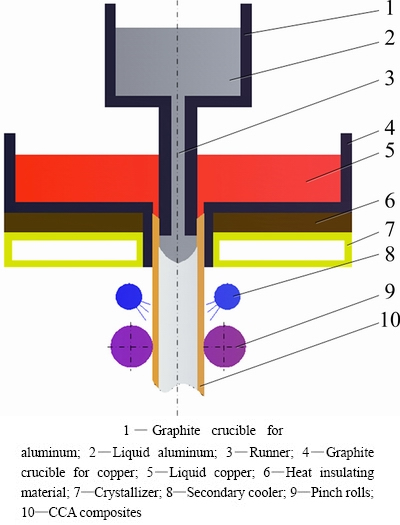
Fig. 1 Schematic diagram of vertical core-filling continuous casting for CCA composites
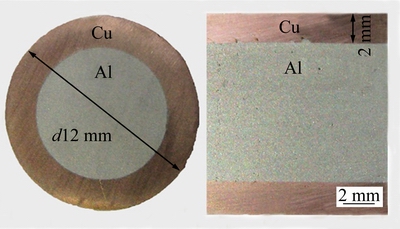
Fig. 2 Macro-morphology of CCA rod
The interfacial microstructure of CCA composite was investigated by scanning electron microscopy (SEM) equipped with energy dispersive spectrometry (EDS). The shear test of CCA sample was carried out with the same approach as that adopted in the previous work [14]. The CCA sample was mounted in a 20 t universal testing machine. A continuous load was applied on the sample with a thickness of 10 mm via a punch until the interface of the sample was failed, and the fracture area of the sample was located at the Cu/Al interface. The phase compositions of the fracture surface and Cu/Al interface were identified using X-ray diffractometry (XRD) and transmission electron microscopy (TEM), respectively.
3 Results and discussion
3.1 Interfacial microstructure of CCA composite
Figure 3 shows the SEM images of interfacial microstructure of CCA composite. It can be seen from Fig. 3(a) that there was a 250 ��m-thick interface between the Cu sheath and Al core. Along the radial direction from the Cu sheath to the Al core, the interface can be divided into three sublayers with different thicknesses and morphologies. The contents of Cu and Al at the interface were measured by EDS analysis. The results are tabulated in Table 1. Based on the EDS analysis and element mapping analysis results (Figs. 3(b) and (c)), it can be seen that the content of Al showed an increasing tendency while that of Cu showed a decreasing tendency along the radial direction from Cu sheath to Al core. Sublayer I with little thickness was predicted to be layered ��1(Cu9Al4) phase. Sublayer II with large thickness was predicted to be cellular ��(CuAl2) phase. In sublayer II, acicular compounds were predicted to be residual ��2(Cu3Al2+x) phase corresponding to the composition analysis result. Sublayer III had a distinct feature of lamellar eutectic morphology.
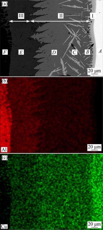
Fig. 3 SEM image (a) and EDS element mappings (b, c) of interface in CCA composites
Table 1 Results of EDS analysis of interface in CCA composites
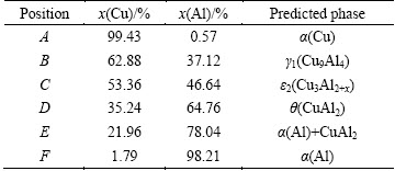
Figure 4 shows the phase compositions at the fracture interface of CCA composite. The results showed that Al side was mainly composed of ��(CuAl2) phase, while Cu side might contain ��1(Cu9Al4) and ��2(Cu3Al2+x) phases in addition to ��(CuAl2) phase. SU et al [10] only mentioned ��(CuAl2) and ��1(Cu9Al4) phases but without ��2(Cu3Al2+x) phase when analyzing the interfacial microstructure of CCA composite. In order to identify the phases in the sublayers, TEM analysis was carried out and the results are illustrated in Fig. 5. As shown in Fig. 5, the electron diffraction patterns confirmed that the interface of CCA composite contained ��2(Cu3Al2+x), ��1(Cu9Al4) and ��(CuAl2) phases. The ��1(Cu9Al4) phase is a cubic structure with a lattice constant of a=b=c= 0.87068 nm, while the ��2(Cu3Al2+x) phase is a high- temperature phase and has close-packed hexagonal structure with lattice constants of a=0.4146 nm and c=0.5063 nm.
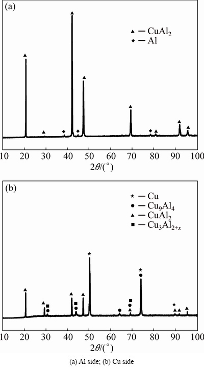
Fig. 4 XRD patterns of interface in CCA composites after shear test
3.2 Interfacial formation mechanism of CCA composite
Figure 6 shows the relation that Cu/Al interface temperature varies with time [13]. It can be seen that the cooling rate of Cu/Al interface was very fast. Therefore, the interfacial bonding of Cu/Al was a continuous cooling solid-liquid reaction process, and the formation of Cu/Al interfacial layer was a result of the comprehensive effect of interfacial reaction-diffusion and rapid solidification.

Fig. 5 TEM bright field images and corresponding selected area electron diffraction patterns of interface in CCA composites
Figure 7 shows the Cu-Al binary phase diagram. T1 is the initial contact temperature between solid Cu and liquid Al (about 700 ��C), T2 is the melting point of Al (660.452 ��C), T3 is the temperature of peritectic reaction L+��2=��1 (624 ��C) and T4 is the temperature of peritectic reaction of L+��1=�� (592 ��C). Liquid Al flowed from the Al honeycomb duct to contact with the inner wall of solid Cu tube at T1. The diffusion of Al atoms to Cu matrix led to a rapid dissolution of Cu, forming a thin liquid DL at the Cu/Al interface. When reaching a certain concentration, Cu-Al compounds nucleated in DL [15]. Combined with the binary phase diagram of Cu-Al (Fig. 7), the phase of ��2(Cu3Al2+x), ��1(Cu9Al4) and ��(Cu3Al) could be generated at the temperature T1. Due to the slow growth rate of �� phase [16] and the short contact reaction time of Cu/Al, ��(Cu3Al) phase could be ignored.
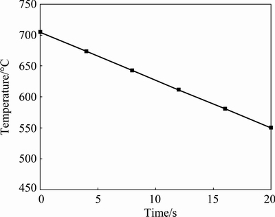
Fig. 6 Relationship between temperature of Cu/Al interface and time
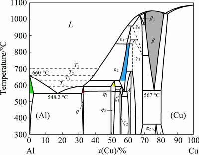
Fig. 7 Cu-Al binary phase diagram
The study on the forming sequence of Cu-Al interfacial compound phases is crucial to reveal the interfacial formation mechanism. LEE et al [17] introduced a scheme to predict the intermetallic compound which formed firstly at the substrate/solder interface during the soldering process. Firstly, a local equilibrium was assumed at the interface between the substrate and the liquid solder. Then, the nucleation driving forces of individual phases were calculated. Finally, the compound which formed firstly at the substrate/solder interface was successfully predicted. This theory was applied in this work to calculate the nucleation driving force of ��2(Cu3Al2+x) and ��1(Cu9Al4) phases.
When solid Cu contacted with liquid Al, the Cu solid solution and liquid DL formed, and the composition reached partial equilibrium at the interface. The thermodynamics condition of two-phase equilibrium is that the chemical potential of each element in each phase is equal, which can be achieved by common tangent rule of molar free energy of rich-Cu FCC phase and the liquid phase. Molar Gibbs free energy of rich-Cu FCC phase and the liquid phase can be obtained through sub-regular solution model (SRSM) approximately [18]:

 (1)
(1)
where i stands for �� or L phase; x is the mole fraction of Cu; Gi is Gibbs free energy of pure metal;  ,
,  and
and  are interaction coefficients, which are related to the temperature. The Gibbs free energy calculation formulas of Cu and Al solid phase of face-centered cubic are as follows [19].
Solid phase of pure Al:
 =-11278.4+188.684T-31.7482TlnT-1.231��1028/T9 (2)
Solid phase of pure Cu:
=-7770.46+130.485T-24.1124TlnT-0.00265684T2+1.29223��10-7T3+52478T-1 (3)
Interaction coefficient:
 =-53520+2T,
  =38590-2T,
  =1170 (4)
The Gibbs free energy calculation formulas of liquid Cu and Al are as follows.
Liquid phase of pure Al:
 =-795.996+177.43-31.7482TlnT (5)
Liquid phase of pure Cu:
 =5194.28+120.973T-24.1124TlnT-0.00265684T2+52478/T+1.29223��10-7T3-5.849��10-21T7 (6)
Interaction coefficient in liquid phase:
 =-66622+8.1T, =46800-90.8T+10TlnT,
=-2812 (7)
��2(Cu3Al2+x) phase can be processed by two sublattice model [20], and the general formula of this model is MaNc. The ��2(Cu3Al2+x) can be regarded as interstitial solid solution Cu1(Al,Va)1, which can be seen as solution consisting of two compounds of Cu1Al1 and Cu1Va1. Here, Cu1Va1 was pure Cu. Mole fraction of the two components was identical to the two nodes in sublattice. The molar Gibbs free energy of interstitial solid solution Cu1(Al, Va)1 is as follows:

 (8)
(8)
where  and
and  are the Gibbs free energies of two compounds, respectively.
It can be shown by
=+ -36976+1.2T,
= + (9)
+ (9)
where is the Gibbs free energy of Cu (BCC).
It can be written as follows:
=-3753.46+129.23T-24.1124TlnT-0.00265684T2+52478T-1+1.29223��10-7T3 (10)
where yAl and yVa are the mole fractions of two compounds, as well as two nodes in the gap sublattice. At 973 K, the composition of ��2(Cu3Al2+x) is about xCu=0.56, so yAl=0.786 and yVa=0.214. At 933 K, the composition of ��2(Cu3Al2+x) is about xCu=0.555, so yAl=0.802 and yVa=0.198.
IAlVa is the interaction energy, and the interaction parameters can be expressed as follows:
L0=7600-24T, L1=-72000 (11)
Equation (8) is the molar Gibbs free energy of 1 mole Cu1(Al,Va)1, so the Gibbs free energy of 1 mole solid solution can be expressed as follows:

 (12)
(12)
where �� and c are equal to 1.
The Gibbs free energy of ��1(Cu9Al4) can be expressed as follows:
 =
= +
+ -219258-45.5T (13)
The chemical potential of Cu and Al in solution is the partial molar Gibbs free energy. The chemical potential of two components Cu and Al in L and �� phases can be obtained by
 (14)
(14)
 (15)
(15)
 (16)
(16)
 (17)
(17)
where  ,
,  ,
,  and
and represent the chemical potentials of Cu, Al in L and �� phases, respectively.
Partial differential of molar Gibbs free energy of L and �� phase can be expressed by the following formulas, respectively:


 (18)
(18)


 (19)
(19)
The chemical potentials are equal when two phases reach equilibrium:
 (20)
(20)
 (21)
(21)
The following equations about xL and x�� can be gotten, and then xL and x�� under a certain temperature can be obtained:
 (22)
(22)
 (23)
(23)
By substituting xL and x�� into Eqs. (14)-(17), the chemical potentials of Cu and Al in L phase and �� phase can be found out, respectively. At 973 K, the phase equilibrium composition is about xL=0.480 and x��=0.545, and the chemical potentials of pure Al and Cu are ��Al=-5.32��104 J/mol and ��Cu=-6.90��104 J/mol, respectively. At 933 K, the phase equilibrium composition is about xL=0.460 and x��=0.525, and the chemical potentials of pure Al and Cu are ��Al=-4.88�� 104 J/mol and ��Cu=-6.76��104 J/mol, respectively.
The calculation method of driving force about IMC is shown in Fig. 8. Driving force of nucleation of ��1(Cu9Al4) and ��2(Cu3Al2+x) is the difference between common tangent of two phases (L, ��) and the molar Gibbs free energy of IMC, and its calculation formula is as follows:
 (24)
(24)

 (25)
(25)
where  is the nucleation driving force of ��1(Cu9Al4), and
  is the nucleation driving force of ��2(Cu3Al2+x). At 973 K, =838 J/mol and =1201 J/mol. At 933 K, = 711 J/mol and =1485 J/mol. The results showed that the nucleation driving force of ��2(Cu3Al2+x) was greater than that of ��1(Cu9Al4), which indicated that ��2(Cu3Al2+x) was likely to precipitate first.

Fig. 8 Nucleation driving forces of ��1 and ��2 IMCs in face-centered cubic solid solution and liquid in metastable state
In addition, ��1(Cu9Al4) possessed the characteristic of solid reaction diffusion [21]. Thus, ��2(Cu3Al2+x) formed firstly at the Cu substrate, and then grew up into continuous layer in a very short time, as shown in Fig. 9(a).
From T1 to T2 in Fig. 6, ��1(Cu9Al4) formed by solid phase reaction between ��2(Cu3Al2+x) and Cu, as shown in Fig. 9(b). In addition, the growth of ��1(Cu9Al4) and ��2(Cu3Al2+x) accorded with the mechanism of formation and dissolution [22]. The IMCs/Cu interface moved towards Cu substrate and new IMCs were generated. Meanwhile, due to the dissolution of the IMC, the IMCs/liquid DL interface also moved towards Cu substrate. Therefore, this movement speed difference led to the growth of IMCs. In addition, the diffusion of copper atoms in liquid aluminum made liquid DL thicker. Because the diffusion coefficient of copper in liquid aluminum was much larger than that of the copper atoms in the solid aluminum, the thickness of liquid DL was larger than that of IMC.
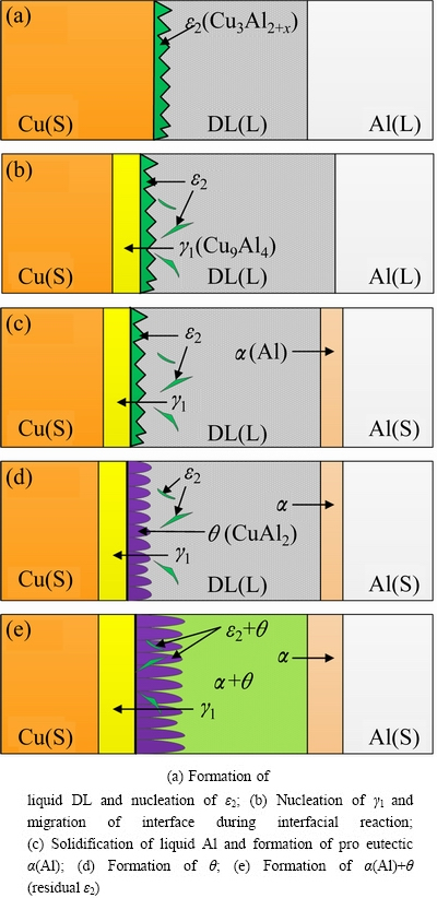
Fig. 9 Schematic diagram of forming process of interface of CCA composite fabricated by core-filling continuous casting (DL��Diffusion layer, S��Solid, L��Liquid)
From T2 to T3, due to the higher melting temperature of Al than the liquid DL, the Al in Cu tube solidified while the liquid DL remained in liquid. As the concentration gradient was increased in the liquid DL, the IMC/liquid DL interface moved towards Cu (see Fig. 9(c)).
From T3 to T4, the peritectic reaction of L+��2=��1 happened at T3, and L+��1=�� happened at T4. Therefore, as shown in Fig. 9(d), ��2(Cu3Al2+x) phase transformed to ��(CuAl2) phase gradually. However, the high cooling rate caused unbalanced peritectic transformation, which led to the acicular ��2(Cu3Al2+x) residues in the interface layer.
Below T4, pre-eutectic ��(CuAl2) appeared in liquid DL of Cu side and pre-eutectic ��(Al) phase appeared in liquid DL of Al side, as shown in Fig. 9(e). At 548.2 ��C, the eutectic reaction L=��+�� happened and the eutectic structure (��(CuAl2)+��(Al)) formed. Due to the slow diffusion rate of solid state reaction and high cooling rate, interfacial diffusion could be ignored after solidification of liquid DL.
4 Conclusions
1) According to the analysis results of SEM, XRD and TEM, the interfacial structure of CCA composite contained three sublayers: Sublayer I was layered ��1(Cu9Al4) phase, Sublayer II was cellular ��(CuAl2) and acicular residual ��2(Cu3Al2+x) phases, and Sublayer III was ��(Al)+��(CuAl2) pseudo eutectic structure.
2) The nucleation driving force of ��2(Cu3Al2+x) was greater than that of ��1(Cu9Al4), which indicated that ��2(Cu3Al2+x) formed firstly at the Cu side interface.
3) The ��1(Cu9Al4) phase formed through solid diffusion reaction between ��2(Cu3Al2+x) and solid Cu. The ��(CuAl2) and ��(CuAl2)+��(Al) phases mainly formed by peritectic reaction and eutectic reaction, respectively.
References
[1] GIBSON A. The economics of copper clad aluminum bimetallic cables [J]. Wire & Cable Technology International, 2005, 33(4): 82-83.
[2] KAZUYUKI N, KAZUO M, CHIHIRO H. Development of manufacturing process of clad bar by rotary rolling [J]. Isij International, 1997, 37(9): 899-905.
[3] RHEE K Y, HAN W Y, PARK H J, KIM S S. Fabrication of aluminum/copper clad composite using hot hydrostatic extrusion process and its material characteristics [J]. Materials Science and Engineering A, 2004, 384(1-2): 70-76.
[4] WU Yun-zhong, MA Yong-qing, LIU Shi-yong, ZHANG Yang. Machining procedure and solid-state bonding mechanism of clad-process welding copper clad aluminum wire [J]. Welding & Joining, 2006(4): 40-42. (in Chinese)
[5] ZHANG Jian-yu, YAO Jin-jin, ZENG Xiang-yong, HAN Yan-qiu, WU Chun-jing. Research progress of copper cladding aluminum composites [J]. The Chinese Journal of Nonferrous Metals, 2014, 24(5): 1275-1284. (in Chinese)
[6] XIE Jian-xin, WU Chun-jing, LIU Xue-feng. A novel forming process of copper cladding aluminum composite materials with core-filling continuous casting [J]. Materials Science Forum, 2007, 539(543): 956-961.
[7] DIVANDARI M, VAHID GOLPAYEGANI A R. Study of Al/Cu rich phases formed in A356 alloy by inserting Cu wire in pattern in LFC process [J]. Materials & Design, 2009, 30(8): 3279-3285.
[8] ZHANG Hong-an, CHEN Gang. Fabrication of Cu/Al compound materials by solid-liquid bonding method and interface bonding mechanism [J]. The Chinese Journal of Nonferrous Metals, 2008, 18(3): 414-420. (in Chinese)
[9] MORENO D, GARRETT J, EMBURY J D. A technique for rapid characterization of intermetallics and interfaces [J]. Intermetallics, 1999, 7(9): 1001-1009.
[10] SU Y J, LIU X H, HUANG H Y, LIU X F, XIE J X. Interfacial microstructure and bonding strength of copper cladding aluminum rods fabricated by horizontal core-filling continuous casting [J]. Metallurgical and Materials Transactions A, 2011, 42(13): 4088-4099.
[11] ZHANG Jian-yu, ZENG Xiang-yong, BEN Li-hua, HAN Yan-qiu, YAO Jin-jin, WU Chun-jing. Formation mechanism of interface in copper cladding aluminum composites fabricated by core-filling continuous casting [J]. The Chinese Journal of Nonferrous Metals, 2014, 24(11): 2755-2761. (in Chinese)
[12] XUE Zhi-yong, QIN Yan-qing, WU Chun-jing. Continuous core-filling cast equipment for the bimetal composite materials of copper cladding aluminum [J]. Journal of University of Science and Technology Beijing, 2005, 27(6): 706-709. (in Chinese)
[13] ZHANG Jian-yu, ZENG Xiang-yong, BEN Li-hua, CUI Xin-peng, WU Chun-jing. Numerical simulation of temperature field of vertical core-filling continuous casting for copper cladding aluminum rods [J]. Hot Working Technology, 2013, 42(15): 89-92. (in Chinese)
[14] SU Ya-jun, LIU Xin-hua, HUANG Hai-you, WU Chun-jing, LIU Xue-feng, XIE Jian-xin. Effects of processing parameters on the fabrication of copper cladding aluminum rods by horizontal core-filling continuous casting [J]. Metallurgical and Materials Transactions B, 2011, 42(1): 104-113.
[15] YU C H, LIN K L. The atomic-scale studies of the behavior of the crystal dissolution in a molten metal [J]. Chemical Physics Letters, 2006, 418(4-6): 433-436.
[16] TANAKA Y, KAJIHARA M, WATANABE Y. Growth behavior of compound layers during reactive diffusion between solid Cu and liquid Al [J]. Materials Science and Engineering A, 2007, 445-446(6): 355-363.
[17] LEE B J, HWANG N M, LEE H M. Prediction of interface reaction products between Cu and various solder alloys by thermodynamic calculation [J]. Acta Materialia, 1997, 45(5): 1867-1874.
[18] DINADALE A T. SGTE data for pure elements [J]. Calphad, 1991, 15(4): 317-425.
[19] BUHLER T, FRIES S G, SPENCER P J, LUKAS H L. A thermodynamic assessment of the Al-Cu-Mg ternary system [J]. Journal of Phase Equilibria, 1998, 19(4): 317-333.
[20] HAO S M, JIANG M, LI H X. Materials thermodynamics [M]. 2nd Edition. Beijing: Chemistry Industry Press, 2010. (in Chinese)
[21] WU Yong-fu, LIU Xin-hua, XIE Jian-xin. Interface of copper cladding aluminum composite materials with rectangle section fabricated by horizontal core-filling continuous casting and its evolvement in rolling process [J]. The Chinese Journal of Nonferrous Metals, 2013, 23(1): 191-200. (in Chinese)
[22] ABDELHADI O M, LADANI L. IMC growth of Sn-3.5Ag/Cu system: Combined chemical reaction and diffusion mechanisms [J]. Journal of Alloys and Compounds, 2012, 537(5): 87-99.
ͭ�������ϲ��Ͻ�������仯���P�γɻ���
�� �1���Ž���2��Ҧ���1��������1���ⴺ��1
1. �����Ƽ���ѧ ���Ͽ�ѧ�빤��ѧԺ������ 100083��
2. �ӱ����̴�ѧ ���繤��ѧԺ������ 056038
ժ Ҫ�����ô�ֱ��о���������Ʊ���ֱ��Ϊ12 mm��ͭ����Ϊ2 mm��ͭ�������ϲ��ϡ�ͨ�� SEM��XRD��TEM �Խ�������仯������������̬�������о����о����������Cu/Al������Ҫ�ɲ�״��1(Cu9Al4)�ࡢ��״��(CuAl2)��ͦ�(Al)+��(CuAl2)������ɣ��ر����ڽ�����֯�й۲쵽��������״Cu3Al2+x�ࡣͨ���ȽϦ�1(Cu9Al4)�ͦ�2(Cu3Al2+x)���κ���������֤���˦�2(Cu3Al2+x)�������ڽ��洦�γɡ����⣬������ʾ��ͭ�������ϲ��Ͻ����γɻ�����
�ؼ��ʣ�ͭ�������ϲ��ϣ���ֱ��о�����������γɻ���
(Edited by Bing YANG)
Foundation item: Project (51274038) supported by the National Natural Science Foundation of China
Corresponding author: Chun-jing WU; Tel:+86-10-62332605; E-mail: cjwuustb@126.com
DOI: 10.1016/S1003-6326(17)60279-6
Abstract: Copper cladding aluminum (CCA) rods with the section dimensions of 12 mm in diameter and 2 mm in sheath thickness were fabricated by vertical core-filling continuous casting (VCFC) technology. The kinds and morphology of interfacial intermetallic compounds (IMCs) were investigated by SEM, XRD and TEM. The results showed that the interfacial structure of Cu/Al was mainly composed of layered ��1(Cu9Al4), cellular ��(CuAl2), and ��(Al)+��(CuAl2) phases. Moreover, residual acicular ��2(Cu3Al2+x) phase was observed at the Cu/Al interface. By comparing the driving force of formation for ��2(Cu3Al2+x) and ��1(Cu9Al4) phases, the conclusion was drawn that the ��2(Cu3Al2+x) formed firstly at the Cu/Al interface. In addition, the interfacial formation mechanism of copper cladding aluminum composites was revealed completely.
