
Effects of shoulder on interfacial bonding during friction stir lap welding of aluminum thin sheets using tool without pin
ZHANG Gui-feng(�Ź��)1, SU Wei(�� ΰ)1, ZHANG Jun(�� ��)1,
WEI Zhong-xin(Τ����)2, ZHANG Jian-xun(�Ž�ѫ)1
1. State Key Laboratory for Mechanical Behavior of Materials, Xi��an Jiaotong University, Xi��an 710049, China;
2. Inspection Institute for Special Equipment, Nanning 530022, China
Received 22 December 2009; accepted 4 May 2010
Abstract:
To separately investigate the potential effects of shoulder on increasing interfacial bonded area and its mechanism, friction stir lap welding (FSLW) of 1.8 mm thick Al sheets without and with insert (copper foil or Al-12Si powders) was conducted using a special tool without pin, respectively. All the FSLW joints (without insert) fractured within top sheet but not along faying surface, suggesting that the shoulder plays an important role comparable or superior to pin in FSLW of thin sheets. Using several specially designed experimental techniques, the presence of forging and torsion actions of shoulder was demonstrated. The fracture surface of the joints with inserts indicates that interfacial wear occurs, which results in the oxide film disruption and vertically interfacial mixing over the area forged by shoulder with a larger diameter than a general pin, especially at the boundary region of weld. The boundary effect can be induced and enhanced by forging effect and torsion effect.
Key words:
friction stir lap welding; forging action; torsion action; boundary effect; interfacial wear; oxide disruption;
1 Introduction
For solid state welding, the joint quality is strongly influenced by the breakdown and/or removal of oxide film and the intimate contact and consequent interfacial mixing (or interdiffusion) between base metals. For friction stir butt welding (FSBW), the oxide film on bond interface can be broken by the crash and stir actions of pin[1], resulting in a zigzag bond line within stir zone[2-5]. The satisfactory property of stir zone should be attributed to the dynamic recrystallization of deposited plasticized material[6] and the improved distribution of residual broken oxide film[2]. It should be emphasized that the pin has indispensably important effect on the oxide film disruption and interfacial mixing because the direction of linear velocity of rotating tool at bond interface is approximately perpendicular to the bond interface, resulting in both the oxide film disruption at bond interface and required horizontally interfacial mixing between left and right sheets. In fact, both the oxide film disruption and interfacial mixing during FSBW are primarily achieved by pin in a greater part of the whole thickness but not by shoulder, except in surficial region.
In the last few years, friction stir lap welding (FSLW) has been studied to replace riveting joining and resistance spot welding in aircraft and automobile industries[7-9]. However, FSLW is more difficult than FSBW because: 1) the bonded area at bond interface is limited by pin with small diameter[10]; 2) both the oxide disruption at the sheet interface[10-11] and the required vertically interfacial mixing between top and bottom sheets are more difficult because the direction of linear velocity of rotating tool at bond interface is approximately parallel to the bond interface[11]; 3) continuous films with remarkable length like flaws and large voids were observed in central nugget, and a long interface around central nugget was also observed, especially on the retreating side[12]. To overcome the disadvantages associated with conventional cylindrical threaded pins, two new pin geometries, namely Flared-TrifluteTM and A-SkewTM tools were developed by the Welding Institute[6, 12]. The design features of the new tools are believed to widen the welding region and improve the mixing action for oxide fragmentation and dispersal at the weld interface[6]. In particular, the lap joints using Skew-stir technique achieved approximately twice maximum tensile load compared with the conventional method, because the extent of bonding was greater across the interface present in Skew-stir welds[12]. In addition, for conventional pin, double-pass technique[8] was developed to eliminate the critical advancing side (for sufficient effective sheet thickness) and make the weld nugget wide. These previous studies on FSLW showed that increasing bonded area and effective sheet thickness should play an important role in successfully obtaining FSLW.
The aim of the present work is to demonstrate the potential effects of shoulder on increasing bonded area via oxide film disruption and vertically interfacial mixing during FSLW of thin aluminum sheets. FSLW of Al sheets was performed using a tool without pin in the two specific cases: with copper foil or Al-Si powder inserts (from fracture surface examination aspect) and without any insert (from normal joint structure observation aspect). The presence of forging effect torsion effect and the resultant boundary effect of shoulder at bond interface caused by the rotating tilted shoulder during FSLW was confirmed.
2 Experimental
Commercially available pure aluminum sheet with a dimension of 100 mm��60 mm��1.8 mm was used as base metal. To independently determine the potential effects of shoulder on increasing interfacial bonded area during FSLW, the pin was removed to eliminate its coupled effect. On the other hand, for practical application, a smooth weld bead without key hole should be obtained using the special tool without pin. A simple columnar tool with a diameter of 15 or 20 mm without pin was used. Such wide tool diameter was selected because small tool diameter made the weld surface rough in our previous experiments[13]. FSLW was performed on a conventional vertical milling machine without an apparatus to apply a vertical pressure to workpieces. In this case, the vertical pressure can not be applied to workpieces when the work table stops to rise. Therefore, the tool was tilted by 3�� to enhance the forging effect of shoulder and improve the intimate contact between the top and bottom workpieces. All samples were welded under identical condition at rotation and traverse speed of 1 250 r/min and 25.3 mm/min, respectively. Considering sound FSLW joint of thin Al sheet can be readily obtained using wide shoulder[13], two kinds of commercial inserts with high melting point, namely Cu foil (50 mm in thickness) and Al-12Si powder (0.1 mm in filling thickness in loose state) were inserted to weaken interfacial bonding and hence directly observe the joint fracture surface.
Fig.1 shows the schematic diagram of the lap joint configuration and the loading configuration in tensile shear test. For the lap joint configuration, the top sheet was placed at retreating side (RS), while the bottom sheet was placed at advancing side (AS). The tool rotated in a clockwise direction. The meanings of the terms of AS and RS in the present work was described in Refs.[7, 14]. Namely, the side of the weld where translation and rotation speed have the same direction is called AS, while the side where they are opposite is called RS[7]. After welding, the joints were evaluated by tensile shear test at a constant crosshead speed of 1 mm/min, and the structure (for normal joint without insert) and fractured surface (for joint with insert) were examined to investigate the effects of shoulder on breaking oxide film and vertically interfacial mixing behavior during FSLW of thin Al sheet.
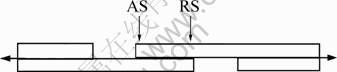
Fig.1 Schematic diagram of lap joint configuration and loading configuration in tensile shear test
For Al/Al joint, Keller��s reagent with the composition of 10% HF, 15% HCl, 25% HNO3 and 50% H2O (volume fraction) is usually used for metallurgical examination of aluminum alloy joint, It tends to make the smooth surface of polished pure aluminum joint specimen rough in our previous studies[13]. The etching reagent for Al/Al joint used in the work was another mixed acid, which was composed of 10% HF, 15% HCl and 75% H2O (volume fraction).
3 Results and discussion
3.1 Property, macro- and micro-structures of FSLW joints
All joints produced by a tool with shoulder diameter of 15 or 20 mm (without pin) fractured at RS, but within top sheet (because of thinning of top sheet) and not along faying surfaces. For a specimen with a nominal tested bonding area of 20 mm �� 24 mm produced by a 20 mm diameter shoulder (without pin), the failure load reached 2.67 kN. Therefore, the diameter of a shoulder has a significant effect on the smooth weld surface forming[13] and joint property.
As expected, the use of wide shoulder is beneficial to improve both weld surface forming and joint property. As a typical sample, the joint produced by a tool with diameter of 15 mm (without pin) was examined in detail. Figs.2(a) and (b) show the optical images of its failure location during tensile shear test and transverse sections structure, respectively. As mentioned above, the joint fractured at weld boundary zone of RS (the arrow in Fig.2(a)), but within top sheet and not along initial bond interface, showing that sound FSLW Al/Al joints were readily obtained even using the special tool without pin. The macrostructure of transverse section of the joint was quite similar to that of a FSLW Al/Al joint produced using a normal tool consisting of a shoulder and a threaded pin, which shows a dish shape[13]. The result indicates that the absence of pins has little effect on the heating behavior and joint cross section profile, although pins have some effect on mechanically disrupting oxide film in classical stir zone. In addition, at the small region adjacent to the weld boundary, the bond line could not be observed at the magnification, showing that a bonded ring would be preferentially formed at the boundary region, while a black bond line could be clearly observed at the central region, as shown in Fig.2(b). Therefore, from the macrostructure of joint transverse section, it was deduced that although the interface to be bonded remained at central region, the initial bond interface at the region inside weld boundary was preferentially removed. The result roughly agrees with the fracture surface at boundary of the joint with Cu foil insert.
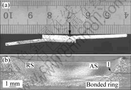
Fig.2 Fracture location (a) and transverse section (b) of FSLW joint of Al/Al assembly using tool of 15 mm shoulder without pin
Fig.3 shows the interfacial microstructure of the Al/Al lap joint produced by a tool with shoulder diameter of 15 mm (without pin) at three distinct regions: the weld boundary on AS, the region inside weld boundary and the central region. From Fig.3(a), it can be seen that the characteristic of the weld boundary on AS is the same as the thermo-mechanically affected zone (TMAZ) of a normal FSW joint[6], namely, a small upward hook was also observed at AS. This phenomenon may be related to the side force usually generated during FSW, the nonuniform distribution of forging effect and the real rotating direction of shoulder end which has a small upward component under tilting condition. The hook formation on AS is beneficial to prevent the worst fracture mode along the initial faying surface.
For the zone inside the hook and adjacent to the weld boundary, vertical intermixing between top and bottom sheets was preferentially achieved, showing zigzag bonded interface with fairly dense microstructure (see Fig.3(b)). The result was consistent with the disappearance of bond line observed at lower magnification in Fig.2(b). From the macrostructure (see Fig.2(b)) and the microstructure of the zone inside weld boundary (see Fig.3(b)), it can be deduced that the favorable vertically intermixed ring with fairly dense structure can be preferentially formed by the individual shoulder at the zone near weld boundary on both AS and RS during FSLW. This phenomenon is called boundary effect by present authors. The formation mechanism of the boundary effect will be analyzed by observing the interface evolution in section 3.2.
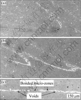
Fig.3 SEM micrograph of Al/Al joint produced by FSLW using tool of 15 mm shoulder without pin at different regions: (a) Weld boundary on AS; (b) Zone inside weld boundary; (c) Central zone
In the contrast, a large number of defects such as voids were present at the central region of bond interface (see Fig.3(c)), showing the vertical intermixing behavior at the central region was poor. In spite of these remaining voids, several intimately bonded micro-zones could be observed.
In the preliminary study, the favorable joint property can be obtained by a tool without pin. It can be attributed to the large overlap length (because wide shoulder must be used to prevent forming rough weld surface), hook formation, boundary effect and some intimately bonded micro-zones at central region, among these factors the boundary effect is the most important for favorable property because the total area of vertically mixed ring with fair dense structure (at both AS and RS) can not be ignored compared to the area of pin. Because 1) the total width of bonded area at faying surface including the bonded ring at perimeter zone (primary bonded area) and some bonded micro-zones at central region (minor bonded area) should be superior or comparable to general pin diameter (3-5 mm), and 2) the great bonded area is beneficial to reduce stress concentration (based on the analysis mode using stress flow line)[12], the wide shoulder plays a more important role than pin in FSLW of thin sheets. On the other hand, the result and discussion mentioned above also suggest that the simple tool without pin can be used to eliminate keyholes for improving surface.
3.2 Fracture surface of joints with insert
Since the FSLW joints produced using a tool with large shoulder diameter (15 or 20 mm) without pin did not fracture along faying surface, an insert (two types of Cu foil and Al-Si powders) was used to weaken the interfacial bond and investigate the interface evolution behaviour during FSLW by fracture surface observation.
Fig.4 shows the fracture surface of FSLW joints with different inserts. The FSLW joint of Al/Cu/Al fractured along the interface between Cu foil and top sheet, as shown in Figs.4(a) and (b). A high fracture load of 2.5 kN for a nominal tested bonding area of 20 mm �� 24 mm is obtained. From Figs.4(a) and (b), the disruption of Cu foil and many circular trails on the surfaces of Cu foil can be clearly observed, especially at AS. Furthermore, some remarkable circular wear marks and dimples were observed on the fracture surface of the joint with Al-12Si powders, especially at AS shown in Fig.4(c).
The fracture surface of the joints with insert demonstrates that although the shoulder did not directly contact the insert and bottom sheet, a relative motion occurred between each component of the joints. The disruption of Cu foil, a number of circular wear marks and several dimples suggest that the relative motion is torsion and significant interfacial wear occurs. The presence of torsion action between bond interfaces is useful for mechanically breaking the oxide film by wear during FSLW, resulting in the sharp zigzag bonded interface at boundary region (see Fig.3(b)) and some discontinuous small bonded areas at central interface even under the condition using the special tool without pin (see Fig.3(c)).
There are two key factors to help the establishment of torsion action between bond interfaces during FSLW: the forging action of tilted shoulder and the tangential metal flow driven by rotating shoulder. First, the forging action of shoulder on weld metal is essential for torsion action because the intimate contact between workpieces can be only achieved by forging action. To visually demonstrate that the forging effect can be enhanced by tilting tool using a traditional milling machine, a special backing plate with a pre-drilled hole was used in the confirmatory experiment. In the case of using the special backing plate with a d 4 mm pre-drilled hole and the tool with shoulder diameter of 20 mm without pin, the extrusion of plasticized Al into the pre-drilled hole was observed after welding, as shown in Figs.5(a) and (b). It can be clearly seen that the length of extruded plasticized aluminum into the pre-drilled hole at 3�� tilt angle (5.3 mm) was much longer than that at 0�� tilt angle (2.6 mm). The result suggests that vertically forging effect could be introduced and enhanced by tilting tool during FSLW even using a common vertical milling machine.
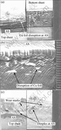
Fig.4 Fracture surface of FSLW joint of Al/Cu/Al ((a) At low magnification; (b) At relatively high magnification) and Al/Al-12Si/Al (c) Produced by tool with 20 mm diameter but without pin showing disruption of Cu foil on AS (a), torsion trail at Cu foil interface (b), and worn Al interface (c)
Second, the tangential flow of weld metal within upper sheet is essential to establish a velocity gradient across bond interface. Previous study on material flow during FSW reported the presence of the metal flow driven by shoulder. For example, KUMAR and KAILAS[15] separately analyzed the role of pin and shoulder on weld formation using a special backing plate with a slight inclination angle and demonstrated that there were two different modes of material flow regimes involved in the friction stir weld formation, namely pin-driven flow and shoulder-driven flow. Especially, when the axial load increases to a critical value, the sub-surface material flow driven by shoulder becomes intense. REYNOLDS[16] also pointed out that in the case of welding thin sheets, the material in the greater part of the whole thickness and near the crown surface of the weld is dragged from RS across the weld centerline and deposited on the AS. Therefore, the torsion action at bond interface results from the shoulder driven flow of weld metal within top workpiece assisted by forging effect.
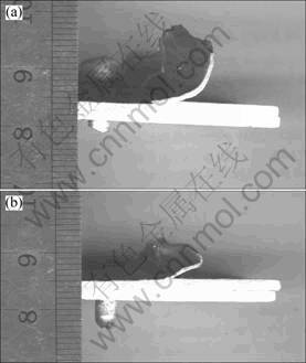
Fig.5 Extrusion behavior of plasticized Al into pre-drilled hole within backing plate after FSLW using tool of 20 mm diameter without pin at different tool tilting angle: (a) 0��; (b) 3��
On the other hand, the disruption behavior of surface oxide film by wear depends on the relative velocity between workpieces (the bottom sheet can be roughly considered as completely fixed because it is far from rotating shoulder) and the temperature at bond interface[17]. SINGH and ALPAS[17] reported that severe wear occurs above 150 ��C. When torsion action occurs at interface, although the end of shoulder has the same angular velocity at different zones, the interfacial wear and the resultant oxide disruption preferentially occurs at weld boundary, because 1) the linear velocity of shoulder at boundary region is higher than that at central region, and 2) the temperature rises to a certain extent at boundary region. Therefore, although the shoulder does not directly contact the bond interface, the boundary effect is considered to be a result of preferential wear at perimeter region of weld between base metals caused by metal flow and its velocity gradient across bond interface which is induced and enhanced by forging effect and torsion effect. Further study on metal flow is necessary to understand the interfacial wear and mixing.
4 Conclusions
1) The FSLW joints using a tool with 15 or 20 mm diameter shoulder without pin fractured at weld boundary zone of RS, but within top sheet and not along initial bond interface. The absence of pin has little effect on heating behavior and joint cross section profile in FSLW of thin sheet. A small hook was also formed at the boundary on AS, which can avoid the worst fracture path through the initial bond interface.
2) For the joints with insert, the disruption of Cu foil insert, the circular wear trails and dimple can be clearly observed on the joint fracture surface, especially at AS. The result indicated that the rotating shoulder can result in ��torsion action�� between bond interfaces, and thus disrupting oxide film by wear.
3) By using a special backing plate with predrilled hole and comparing the length of plasticized aluminum extruded into the predrilled hole in different cases with and without tilting angle (3��), it was demonstrated that the forging effect can be enhanced by tilting tool, which is essential for vertically intimate contact between top and bottom sheets during FSLW.
4) Both macro- and micro-structures of the Al/Al joint showed that favorable vertically intermixed ring with fair dense structure and sharp zigzag bonded interface can be preferentially formed by the individual shoulder at perimeter zone during FSLW, while the vertical intermixing behavior at the central region was poor. This phenomenon, called ��boundary effect��, can be considered to be a result of preferential wear at boundary region, which can be induced and enhanced by ��forging effect�� and ��torsion effect��.
5) The wide shoulder can play more important role rather than pin in FSLW of thin sheets primarily because the total width of bonded area at faying surface including the bonded ring at perimeter zone (primary bonded area) and the bonded micro-zones at central region (minor bonded area) should be superior or comparable to general pin diameter.
6) The three effects are beneficial to the disruption of oxide film, inducing vertically interfacial mixing, and hence increasing bonded area especially at perimeter zone of weld.
References
[1] DAWES C J, THOMAS W M. Friction stir welds aluminum alloys [J]. Weld J, 1996, 75(3): 41s-45s.
[2] SATO Y S, YAMASHITA F, SUGIURA Y, Park SHC, KOKAWA H. FIB-assisted TEM study of an oxide array in the root of a friction stir welded aluminum alloy [J]. Scripta Mater, 2004, 50(3): 365-369.
[3] OKAMURA H, AOTA K, SAKAMOTO M, EZUMI M, IKEUCHI K. Behavior of oxide during friction stir welding of aluminum alloy and its influence on mechanical properties [J]. Quarterly Journal of the Japan Welding Society, 2001, 19: 446-456. (in Japanese)
[4] LIU H J, CHEN Y C, FENG J C. Effect of zigzag line on the mechanical properties of friction stir welded joints of an Al-Cu alloy [J]. Scripta Mater, 2006, 55: 231-234.
[5] ZHOU C, YANG X, LUAN G. Effect of oxide array on the fatigue property of friction stir welds [J]. Scripta Mater, 2006, 54: 1515-1520.
[6] MISHRA R S, MA Z Y. Friction stir welding and processing [J]. Mater Sci Eng R, 2005, 50: 1-78.
[7] FERSINI D, PIRONDI A. Fatigue behaviour of Al2024-T3 friction stir welded lap joints [J]. Engineering Fracture Mechanics, 2007, 74: 468-450.
[8] CEDERQVIST L, REYNOLDS A P. Factors affecting the properties of friction stir welded aluminum lap joints [J]. Weld J, 2001, 80(12): 281s-287s.
[9] KATOH K, TOKISUE H, MIURA K. Microstructure and mechanical properties of lap friction seam welded 5052 aluminum alloy joint [J]. Journal of Light Metal Welding and Construction, 2007, 45(1): 14-22. (in Japanese)
[10] THOMAS W M, STAINES D G, NORRIS I M, FRIAS R D. Friction stir welding tools and Developments [J]. Welding in the World, 2003, 47(1/2): 10-17.
[11] ENMOTO M. Characteristics of friction stir welded lap joint of A6061 alloy [J]. Journal of Light Metal Welding and Construction, 2001, 39(1): 6-9. (in Japanese)
[12] CANTIN G M D, DAVID S A, THOMAS W M, LARA-CURZIO E, BADU S S. Friction skew-stir welding of lap joints in 5083-O aluminum [J]. Sci Technol Weld Joi, 2005, 10(3): 268-280.
[13] ZHANG J. Friction stir lap welding (FSLW) of Al sheets and the combination of friction stir process (FSP) with FSLW for fabrication of surface composite [D]. School of Materials Science and Engineering, Xi��an: Xi��an Jiaotong University, 2009: 15-20. (in Chinese)
[14] THREADGILL PL. Terminology in friction stir welding [J]. Sci Technol Weld Joi, 2007, 12(4): 357-360.
[15] KUMAR K, KAILAS S V. The role of friction stir welding tool on material flow and weld formation [J]. Mater Sci Eng A, 2008, 485: 367-374.
[16] REYNOLDS A P. Flow Visualization and Simulation in FSW [J]. Scripta Mater, 2008, 58(5): 338-342.
[17] SINGH J, ALPAS A T. High-temperature wear and deformation processes in metal matrix composites [J]. Metall Mater Trans A, 1996, 27(10): 3135-3148.
Corresponding author: ZHANG Gui-feng; Tel: +86-29-82663115; E-mail: gfzhang@mail.xjtu.edu.cn
DOI: 10.1016/S1003-6326(10)60632-2
