
Trans. Nonferrous Met. Soc. China 29(2019) 2496-2505
Microstructure and impact mechanical properties of multi-layer and multi-pass TIG welded joints of Al-Zn-Mg alloy plates
Qing-wei GAO1, Feng-yuan SHU2, Peng HE3, Wen-bo DU4
1. College of Materials Engineering, Shanghai University of Engineering Science, Shanghai 201620, China;
2. Shandong Provincial Key Laboratory of Special Welding Technology, Harbin Institute of Technology at Weihai, Weihai 264209, China;
3. State Key Laboratory of Advanced Welding and Joining, Harbin Institute of Technology, Harbin 150001, China;
4. National Key Laboratory for Remanufacturing, Beijing 100072, China
Received 27 February 2019; accepted 18 August 2019
Abstract:
The microstructure and mechanical properties of multi-layer multi-pass TIG welded joints of Al-Zn-Mg alloy plates were studied. The phase constituent and microstructure of different regions of the welded joints were characterized by scanning electron microscopy (SEM), X-ray diffraction (XRD), transmission electron microscopy (TEM) and energy disperse spectrum (EDS), while the mechanical properties were evaluated according to the impact test. A dispersively distributed spherical and needle-like ��(MgZn2) phase was obtained in the welding seam. The phase composition of the heat-affected zone (HAZ) was ��(Al)+��(MgZn2)+Al6Mn, and there were a large number of dispersively precipitated nanoscale particles. The welded joint zone had the highest impact toughness as compared with the other parts of the joint. The MgZn2 phase in the weld zone contributed to the improved toughness of the joint. Al2MgCu phase in HAZ was proven to act as a crack source during fracture.
Key words:
Al-Zn-Mg alloy; thick plates; multi-layer TIG welding; microstructure; impact mechanical property;
1 Introduction
Aluminum alloys were widely used in aircraft structures, light equipment, high-speed train structures and military facilities because of high conductivity, good processability, excellent corrosion resistance and toughness [1-4]. They had played a key role in the car body materials for urban railway vehicles and armor structures [5-9]. As a medium strength alloy among the Al-Zn-Mg systems, AA7A52 was suitable for high- strength weldable equipments and contained about 4.6% Zn and 2.5% Mg [10]. Al-Zn-Mg aluminum alloy exhibited the highest strength at room temperature as aluminum alloy structural material [11]. After age strengthening by heat treatment, the mechanical properties such as hardness and tensile strength of AA7A52 were evidently improved. The alloy had the advantageous characteristics of wide quenching range, easy casting and good formability. After rolling, solution treatment and aging treatment, alloy plates with excellent comprehensive properties could be obtained [12].
The requirement for lightweight equipment made thick plate aluminum alloy of different specifications the optimum choice for structural materials. Narrow gap welding was an effective way to improve the welding efficiency of thick plates and shortened the welding time. There were many welded structural parts in engineering machinery products, whose quality directly determined the quality, performance and reliability of the whole machine [13-17]. Different welded structural parts were required to maintain a certain static load strength, impact strength and fatigue strength. Welding process parameters, welding methods and welding wires were the main factors affecting the quality of welded joints. The welding methods of Al-Zn-Mg alloys had been widely reported including metal inert gas shielded welding (MIG) [18,19], tungsten inert gas welding (TIG) [20,21], laser beam welding (LBW) [22,23] and friction stir welding (FSW) [24,25], etc.
The mechanical properties of thick plate aluminum alloy joints were closely related to the microstructure and stress distribution of the joints. In the multi-layer and multi-pass welding process, the evolution of microstructure and stress distribution of the thick-plate welded joint was complicated. In this work, the microstructure and impact mechanical properties of multi-layer and multi-pass TIG welded joints of thick-plate AA7A52 were studied systematically, after which the fracture mechanism was revealed.
2 Experimental
The AA7A52 plate with thickness of 20-40 mm and ER5356 with diameter of 1.6 mm were selected as welding base metal and welding wire, respectively, of which the chemical compositions are shown in Table 1. The oxide film and oil stain on the surface of the welded plate were removed by mechanical grinding and acetone cleaning, then the plate was dried in a drying oven at 40 ��C for 10 min. The variable polarity TIG welding method was used to remove the oxide film in the arc region by cathode atomization, and the positive to negative half-wave time ratio was 1:1. The cooling process between the welding passes was to ensure that the interlayer temperature was lower than 80-100 ��C, and interlayer cleaning was performed after cooling down. In order to prevent the generation of hydrogen holes in the weld, argon with purity of 99.99% was continuously provided during the welding process. During the rooting welding process, a welding pad was used to provide an argon protection environment for the back of the weld seam. The plates were assembled and horizontally fixed according to the dimensions of the groove as shown in Fig. 1(a). There were 21 weld beads in total, of which the welding process was divided into three parts. The processing parameters and welding schematic diagram are shown in Table 2 and Fig.1(b), respectively.

Fig. 1 Schematic of bevel used in TIG welding (a) and welding process (b)
Table 1 Chemical composition of AA7A52 and ER5356 (wt.%)
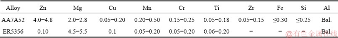
Table 2 TIG welding parameters

Specimens of the welded joints were obtained by line cutting machine and ground by the waterproof abrasive paper from the size of 400# to 1200#. Specimens for microstructural studies were polished and etched for 120 s in a solution containing 1 mL HF, 1.5 mL HCl, 2.5 mL HNO3, and 95 mL deionized H2O. The phases presented in the weld seam were identified with X-ray diffractometer (XRD; D/max 2500, Rigaku Corporation, Tokyo, Japan) using Cu K�� radiation. For selected area diffraction analysis by transmission electron microscopic (TEM-SAD) thin foil specimens were successively prepared by mechanical thinning and electrolytic thinning and observed using a JEOL-2100 transmission electron microscope (JEOL Ltd., Tokyo, Japan) at an operating voltage of 200 kV. Microstructural and composition analysis of weld metal was performed using NANOSEM 450 scanning electron microscope (SEM, FEI Company, Hamilton, Ohio) and Oxford INCA X-ray energy dispersive spectrometer (EDS; Oxford Instruments, Abingdon, United Kingdom), respectively. The Charpy impact test was performed to determine the impact mechanical properties of materials and the impact fracture resistance of materials in different characteristic regions. The impact test equipment was a pendulum impact tester with a full load of 1470 N��cm (15 J) and 4900 N��cm (50 J) and the size of the samples is shown in Fig. 2. The sampling position of the welded joint for XRD experiments is shown in Fig. 3. In order to compare the impact toughness of the weld, fusion zone and heat affected zone at different thickness positions, the sampling position of the impact specimen is shown in Fig. 4. The V-notch position of the impact specimen was numerically marked. The notches of Samples 1, 4, and 7 were located on the weld symmetry line, while the notches of Samples 2, 5, and 8 were located on the fusion line with those of Samples 3, 6, and 9 located 8 mm away from the fusion line. Finally, the notches of Samples 10, 11, and 12 were taken from the base metal. Three sets of samples along the thickness direction were 5, 10 and 15 mm from the back of the joint, respectively.

Fig. 2 Schematic of position of XRD samples in weld joint

Fig. 3 Schematic of Charpy impact test and digital impact test
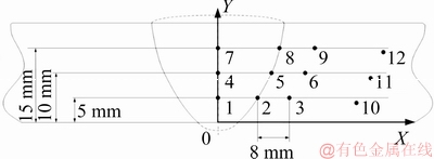
Fig. 4 Schematic of location of impact samples for different characteristic zones
3 Results and discussion
3.1 Microstructure of TIG welded joints
The microstructure of the weld seam should be divided into three characteristic regions including the zone of fine equiaxed grains (Z1), the zone of columnar grains near the fusion line (Z2), and the zone of equiaxed grains at the end of the columnar grains (Z3) as shown in Fig. 5. Figure 6 exhibits the microstructures of the central area in the first to the third, the eleventh and the nineteenth weld passes. The distribution of equiaxed grain is uniform and there is no preferential growth direction during crystallization.
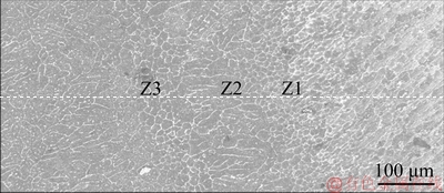
Fig. 5 Microstructure of weld seam
As shown in Fig. 7, the phase compositions of the weld seam and the HAZ are ��(Al) solid solution and ��(Al)+��(MgZn2), respectively. As compared with the diffraction characteristic peaks of pure aluminum, the solid solution effect made the position of the diffraction peaks of the weld shift to the left as a whole. The results showed that the lattice distortion and increase of lattice constant were attributed to the solid solution effect. The solute atom deformed the local lattice by changing the lattice constant and led to the effect of solid solution strengthening. The more the amount of solute atom dissolved in the host lattice, the higher the degree of lattice distortion and the stronger the solid solution strengthening effect. The large cooling rate in the weld made it impossible for the solution atom to precipitate, so the solid solution strengthening effect in the weld zone was the strongest.

Fig. 6 Microstructures of different weld passes
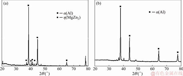
Fig.7 XRD patterns of HAZ (a) and weld seam (b)
The micro morphologies of the strip-shaped particles and the intragranular ellipsoidal particles of weld seam are shown in Fig. 8. The strip-shaped particles were Al3Mg2 phase as shown in Fig. 8(a), whereas intragranular ellipsoidal particles were MgZn2 phase as shown in Fig. 8(b). However, intergranular Al3Mg2 phase was absent in the XRD test result because of its low composition. There were a large number of diffusely distributed nano-sized precipitated particles which were spherical or ellipsoidal in the intragranular. As shown by the EDS result in Fig. 9(a), the main components of intergranular precipitates included Al, Zn, Mg and Cu. Compared with the average content of Al-Zn-Mg alloy, the intergranular precipitates were a Cu-rich zone. As shown in Fig. 9(b), the Cu-rich phase in this region was the Al2MgCu phase.
The TEM-SAED results of Sample 9 in Fig. 4 are shown in Fig. 10. It was shown that there was an Al6Mn phase in the HAZ. The distribution density of the Al6Mn phase was low due to the low content of Mn. The morphology and EDS test results of this phase under TEM are shown in Fig. 10. When the ��(MgZn2) and the Al6Mn phase sufficiently grew and coarsened, a solution- depleted region appeared by the edge of this phase.
3.2 Impact mechanical properties of welded joints

Fig. 8 Micro morphologies of Sample 4 in Fig. 4

Fig. 9 TEM-SAED results in HAZ of Sample 6 in Fig. 4

Fig. 10 TEM-SAED results of Sample 9 in Fig. 4
Impact toughness could be expressed as the ratio of impact absorbing energy to fracture area. The results of the impact energy test obtained with TIG welded joints are shown in Fig. 11 while the sampling position is shown in Fig. 4. From the impact test results of the weld seam zone, the fusion zone and the HAZ, the impact toughness of the joint showed significant local differences. At different thickness positions, the impact toughness of the fusion zone and the impact toughness of the HAZ did not differ significantly. It could be seen that the impact toughness of the weld zone was the highest, while the impact toughness of the HAZ and the fusion zone was equivalent. The fluctuation in impact toughness of welds, fusion lines and HAZ at different thicknesses was within 5%.
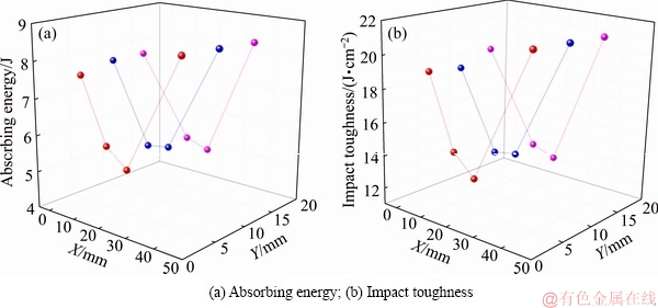
Fig. 11 Charpy impact test results

Fig. 12 Macro and micro fractographs of Sample 4

Fig. 13 Macro and micro fractographs of Sample 5

Fig. 14 Macro and micro fractographs of Sample 6
During the impact fracture process, the sample was plastically deformed and cracks were generated at the root of the notch. The steady expansion stage of cracks formed during a fibre zone (F), a collapsing zone (S) and a shear lip (R). The macro and micro fractographs of the Samples 4-6 are shown in Figs. 12-14, respectively. The crack initiation zone and the fibre zone of Sample 4 were composed of abundant dimples of which the size changed from large to small. The collapsing zone of Samples 5 and 6 consisted of abundant parallel tearing ridge. The crack initiation zone of Sample 6 consisted of tear-shaped surface with a size range of less than 400 ��m. It could be seen that the fracture zone of Sample 4 had only a few parallel tear edges with almost no collapsing zone. The micro morphology of the shear lip of Samples 4-6 exhibited a tear-shaped surface. The fibre zone corresponded to a higher toughness, while the collapsing zone corresponded to a comparatively lower impact absorbing energy. The crack propagation energy of Sample 4 accounted for the largest proportion of the whole absorbed energy during impact process. As a result, the impact toughness was significantly higher than that of Samples 5 and 6. The area of the fibre zone in Sample 4 was the largest with the area of the collapsing zone of Samples 5 and 6 larger than that of Sample 4, which was consistent with the Charpy impact test results.
The load-displacement curve of impact fracture process is shown in Fig. 15(a). The yield load (Fy) and the unsteady expansion force of cracks (Fi) were the demarcation point of these three stages. The total impact energy (Wt) included crack formation energy (Wi) and crack propagation energy (We). The crack Wi was considered to be the area covered by the force- displacement curve between S=0 and S=Sm while the We was considered to be the area covered by the force-displacement curve between S=Sm and S=St. The typical load/absorbed energy-displacement curves of impact specimens in different characteristic areas of welded joints are shown in Figs. 15(b, c, d). The middle part of the sample underwent elastic deformation, yielding, plastic deformation and hardening stages in sequence. Crack initiation occurred when the load increased to the maximum. The impact absorption energy at this time was the Wi which included the elastic deformation energy and plastic deformation energy. As the crack was initiated, the load began to decrease, and the crack expands steadily. When a certain position was reached, the crack was unstable and the load was sharply decreased, resulting in fracture occurred finally. The yield displacement of welding zone was the largest, while that of fusion zone and HAZ was equivalent. The yield strength of welding zone and fusion zone was close to each other while the initiation force of unstable crack propagation in weld seam was equivalent to the HAZ. The impact absorbing energy of the fusion zone and the HAZ 8 mm away from the fusion line was equal and lower than that at the centre of the weld. The crack formation energy of the weld was up to about 3 J while that of the fusion zone and HAZ was less than 2 J. The crack propagation energy values of the weld, HAZ and fusion line were at the same level. Although the maximum force at the centre of the weld was the lowest, the displacement and impact absorption energy during the formation and propagation of cracks were the largest. Therefore, the elongation and toughness of the centre of the weld were the highest during the impact process.
Figure 16 shows the EDS result on the fracture surface of the welded joint. It could be seen that the fracture surface was a Cu-rich region. According to the results of the phase composition of the HAZ, before fracture, Cu was enriched in the intergranular phase and formed a continuous intergranular Al2MgCu phase.

Fig. 15 Schematic of load-displacement (F-S) curve (a), load/absorbed energy-displacement curves of samples from position 4 (b), position 5 (c), and position 6 (d) in Fig. 4, respectively

Fig. 16 EDS result on fracture surface of welded joint
During the tensile fracture process, the Al2MgCu phase acted as a crack source and provided a channel for crack propagation. This intergranular crack was essentially a brittle fracture. Because of the low Cu content, this brittle fracture feature occupied a small area on the whole fracture surface. During the welding process, the dilution effect by base metal determined the microstructure and properties of the weld. The dilution effect dissolved Zn in the base metal into the weld and led to the formation of MgZn2 strengthening phase. This combination could interrupt the continuous distribution of the Al2Mg3 phase and transforming the intergranular morphology into discontinuous intergranular precipitates, which enhanced the precipitation phase strengthening in the weld. The change of phase distribution in the weld increased the grain boundary strengthening effect, so the mechanical properties of the weld were improved.
4 Conclusions
(1) During the welding process, the redistribution of alloy elements near the fusion line of the thick Al-Zn-Mg alloys plate resulted in the dispersion of the ��(MgZn2) phase in the weld seam. The phase composition of the HAZ was ��(Al)+��(MgZn2)+Al6Mn. The ellipsoidal or needle-like �� phase was the most densely distributed nano-sized precipitated particles. The intergranular precipitates were in the form of short rods or continuous strips, and the Al2MgCu phase was distributed in the strip intergranular precipitates.
(2) The weld zone of the thick Al-Zn-Mg alloy TIG welded joint possessed the highest impact toughness during crack formation and propagation. The fluctuation in impact toughness of the fusion zone and the HAZ was less than 5%. Compared with weld zone, HAZ and fusion zone had smaller area of fibre zone.
(3) The MgZn2 phase in the weld zone of AA7A52 contributed to the improvement of welded joint toughness. The Al2MgCu phase in HAZ acted as source of cracks during tensile fracture to provide a channel for crack propagation. Due to the low content of Cu on the fracture surface of the welded joint, the brittle fracture characteristics occupied a small area on the entire fracture surface.
Acknowledgments
Special appreciations shall be sent to Dr. Jia LIU who has been giving wholehearted supports to the corresponding author.
References
[1] HAN Bing, TAO Wang, CHEN Yan-bin, LI Hao. Double-sided laser beam welded T-joints for aluminum-lithium alloy aircraft fuselage panels: Effects of filler elements on microstructure and mechanical properties [J]. Optics & Laser Technology, 2017, 93: 99-108.
[2] DURSUN T, SOUTIS C. Recent developments in advanced aircraft aluminium alloys [J]. Materials & Design (1980-2015), 2014, 56: 862-871.
[3] TISZA M, CZINEGE I. Comparative study of the application of steels and aluminium in lightweight production of automotive parts [J]. International Journal of Lightweight Materials and Manufacture, 2018, 1(4): 229-238.
[4] ZHANG Jin-liang, SONG Bo, WEI Qing-song, BOURELL D, SHI Yu-sheng. A review of selective laser melting of aluminum alloys: Processing, microstructure, property and developing trends [J]. Journal of Materials Science & Technology, 2019, 35(2): 270-284.
[5] GOU G, ZHANG M, CHEN H, CHEN J, LI P, YANG Y P. Effect of humidity on porosity, microstructure, and fatigue strength of A7N01S-T5 aluminum alloy welded joints in high-speed trains [J]. Materials & Design, 2015, 85: 309-317.
[6] WU S C, HU Y N, DUAN H, YU C, JIAO H S. On the fatigue performance of laser hybrid welded high Zn 7000 alloys for next generation railway components [J]. International Journal of Fatigue, 2016, 91: 1-10.
[7] QIN Shun-quan, GAO Zong-yu. Developments and prospects of long-span high-speed railway bridge technologies in China [J]. Engineering, 2017, 3(6): 787-794.
[8] JENA P K, SAVIO S G, KUMAR K S, MADHU V, MANDAL R K, SINGH A K. An experimental study on the deformation behavior of aluminium armour plates impacted by two different non-deformable projectiles [J]. Procedia Engineering, 2017, 173: 222-229.
[9] MURTY A S S, RAMYA P L, GOWTHAM D S, SUDHAKAR I. Simulation and validation of ballistic performance of armor grade AA7075 aluminum alloy using friction stir processing [J]. Materials Today: Proceedings, 2018, 5(9): 20186-20192.
[10] CHEN Chao, CHEN Fu-rong, ZHANG Hui-jing. Surface nanocrystallization of 7A52 aluminum alloy welded joint by aging and ultrasonic impact compound treatment [J]. Rare Metal Materials and Engineering, 2018, 47(9): 2637-2641.
[11] NIE Xiao-wu, ZHANG Li-jun, DU Yong. Experiments and modeling of double-peak precipitation hardening and strengthening mechanisms in Al-Zn-Mg alloy [J]. Transactions of Nonferrous Metals Society of China, 2014, 24(7): 2138-2144.
[12] HUANG L P, CHEN K H, LI S, SONG M. Influence of high- temperature pre-precipitation on local corrosion behaviors of Al-Zn-Mg alloy [J]. Scripta Materialia, 2007, 56(4): 305-308.
[13] SHI Tai-bai, CHEN Wu-jun, GAO Cheng-jun, HU Jian-hui, ZHAO Bing, WANG Xue-ming, WANG Xi-que, LU Guo-fu. Investigation of mechanical behavior of weld seams of composite envelopes in airship structures [J]. Composite Structures, 2018, 201: 1-12.
[14] KASHAEV N, VENTZKE V, CAM G. Prospects of laser beam welding and friction stir welding processes for aluminum airframe structural applications [J]. Journal of Manufacturing Processes, 2018, 36: 571-600.
[15] LEE J M, SEO H D, CHUNG H. Efficient welding distortion analysis method for large welded structures [J]. Journal of Materials Processing Technology, 2018, 256: 36-50.
[16] LI Chun-ling, FAN Ding, YU Xiao-quan, HUANG Jian-kang. Residual stress and welding distortion of Al/steel butt joint by arc-assisted laser welding-brazing [J]. Transactions of Nonferrous Metals Society of China, 2019, 29 (4): 692-700.
[17] LI Yan-jun, WU Ai-ping, LI Quan, ZHAO Yue, ZHU Rui-can, WANG Guo-qing. Effects of welding parameters on weld shape and residual stresses in electron beam welded Ti2AlNb alloy joints [J]. Transactions of Nonferrous Metals Society of China, 2019, 29(1): 67-76.
[18] LI Shuai, DONG Hong-gang, SHI Lei, LI Peng, YE Fei. Corrosion behavior and mechanical properties of Al-Zn-Mg aluminum alloy weld [J]. Corrosion Science, 2017, 123: 243-255.
[19] YAN Shao-hua, CHEN Hui, MA Chuan-ping, NIE Yuan, WANG Xiao-min, QIN Q H. Local corrosion behaviour of hybrid laser-MIG welded Al-Zn-Mg alloy joints [J]. Materials & Design, 2015, 88: 1353-1365.
[20] FENG Yue-hai, CHEN Jia-he, QIANG Wei, WANG Ke-hong. Microstructure and mechanical properties of aluminium alloy 7A52 thick plates welded by robotic double-sided coaxial GTAW process [J]. Materials Science and Engineering A, 2016, 673: 8-15.
[21] LIANG Ying, SHEN Jun-qi, HU Sheng-sun, WANG Hai-chao, PANG Jie. Effect of TIG current on microstructural and mechanical properties of 6061-T6 aluminium alloy joints by TIG�CCMT hybrid welding [J]. Journal of Materials Processing Technology, 2018, 255: 161-174.
[22] ZHANG Liang, LI Xiao-yan, NIE Zuo-ren, HUANG Hui, NIU Lan-qiang. Comparison of microstructure and mechanical properties of TIG and laser welding joints of a new Al-Zn-Mg-Cu alloy [J]. Materials & Design, 2016, 92: 880-887.
[23] ENZ J, RIEKEHR S, VENTZKE V, HUBER N, KASHAEV N. Fibre laser welding of high-alloyed Al-Zn-Mg-Cu alloys [J]. Journal of Materials Processing Technology, 2016, 237: 155-162.
[24] GHANGAS G, SINGHAL S. Investigations of multi-pass friction stir welding for Al-Zn-Mg alloy [J]. Materials Today: Proceedings, 2018, 5(9): 17107-17113.
[25] DENG Ying, PENG Bing, XU Guo-fu, PAN Qing-lin, YIN Zhi-min, YE Rui, WANG Ying-jun, LU Li-ying. Effects of Sc and Zr on mechanical property and microstructure of tungsten inert gas and friction stir welded aerospace high strength Al-Zn-Mg alloys [J]. Materials Science and Engineering A, 2015, 639: 500-513.
Al-Zn-Mg�Ͻ�������TIG���ӽ�ͷ������֯������ѧ����
۬��ΰ1�����Զ2���� ��3�����IJ�4
1. �Ϻ����̼�����ѧ ���Ϲ���ѧԺ���Ϻ� 201620��
2. ��������ҵ��ѧ(����) ɽ��ʡ���ֺ��Ӽ����ص�ʵ���ң����� 264209��
3. ��������ҵ��ѧ �Ƚ����������ӹ����ص�ʵ���ң������� 150001��
4. �����켼�������ص�ʵ���ң����� 100072
ժ Ҫ���о�Al-Zn-Mg�Ͻ�������TIG���ӽ�ͷ������֯�ͳ����ѧ���ܡ�ͨ��ɨ���������(SEM)��X��������(XRD)�����������(TEM)������ɫɢ��(EDS)�Ժ��ӽ�ͷ��ͬ���������ɺ�����֯���б�����ͬʱ������г����ѧ���ܲ��ԡ���������������в�����ɢ�ֲ�����״����״��(MgZn2)�ࡣ������Ӱ�������������Ϊ��(Al)+��(MgZn2)+Al6Mn�������ڴ�����ɢ�ֲ��������������������ӽ�ͷ����������Ͷ���ߣ����ӽ�ͷ�������е�MgZn2�������ڽ�ͷ���Ե���ߡ�������Ӱ������Al2MgCu���ڶ��ѹ�����������Դ�����á�
�ؼ��ʣ�Al-Zn-Mg�Ͻ𣻺�壻���TIG���ӣ�����֯�������ѧ����
(Edited by Xiang-qun LI)
Foundation item: Project (ZR2016EEQ03) supported by the Shandong Province Natural Science Foundation, China; Project (2018M641822) supported by the China Postdoctoral Science Foundation-General Program; Project (HIT.NSRIF.201703) supported by the Natural Scientific Research Innovation Foundation in HIT, China
Corresponding author: Feng-yuan SHU; Tel: +86-15266123725; E-mail: surfacescience@163.com
DOI: 10.1016/S1003-6326(19)65157-5
Abstract: The microstructure and mechanical properties of multi-layer multi-pass TIG welded joints of Al-Zn-Mg alloy plates were studied. The phase constituent and microstructure of different regions of the welded joints were characterized by scanning electron microscopy (SEM), X-ray diffraction (XRD), transmission electron microscopy (TEM) and energy disperse spectrum (EDS), while the mechanical properties were evaluated according to the impact test. A dispersively distributed spherical and needle-like ��(MgZn2) phase was obtained in the welding seam. The phase composition of the heat-affected zone (HAZ) was ��(Al)+��(MgZn2)+Al6Mn, and there were a large number of dispersively precipitated nanoscale particles. The welded joint zone had the highest impact toughness as compared with the other parts of the joint. The MgZn2 phase in the weld zone contributed to the improved toughness of the joint. Al2MgCu phase in HAZ was proven to act as a crack source during fracture.
