
Trans. Nonferrous Met. Soc. China 31(2021) 2287-2306
Corrosion and wear resistance of AZ31 Mg alloy treated by duplex process of magnetron sputtering and plasma electrolytic oxidation
Bing-jian WEI, Yu-lin CHENG, Yuan-yuan LIU, Zhun-da ZHU, Ying-liang CHENG
College of Materials Science and Engineering, Hunan University, Changsha 410082, China
Received 31 August 2020; accepted 8 April 2021
Abstract:
In order to improve the wear and corrosion resistance of AZ31 magnesium alloy, a magnetron-sputtered Al layer with a thickness of 11 ��m was firstly applied on the alloy, and then treated by plasma electrolytic oxidation (PEO) in an aluminate and silicate electrolytes, respectively. The performance of PEO coatings was investigated by dry sliding wear and electrochemical corrosion tests. The aluminate coating exhibits excellent wear resistance under both 10 and 20 N loads. The silicate coating only shows low wear rate under 10 N, but it was destroyed under 20 N. Corrosion tests show that the Al layer after magnetron sputtering treatment alone cannot afford good protection to the Mg substrate. However, the duplex layer of PEO/Al can significantly improve the corrosion resistance of AZ31 alloy. Electrochemical tests show that the aluminate and silicate coatings have corrosion current densities of ~1.6��10-6 and ~1.1��10-6 A/cm2, respectively, which are two orders lower than that of the un-coated AZ31 alloy. However, immersion tests and electrochemical impedance spectroscopy (EIS) show that the aluminate coating exhibits better long-term corrosion protection than silicate coating.
Key words:
AZ31 magnesium alloy; magnetron sputtering; plasma electrolytic oxidation; dry sliding wear; corrosion;
1 Introduction
Owing to their high specific strength, excellent castability, good machinability and high raw material resources, magnesium and its alloys have attracted much attention in automotive, aerospace, biomedical applications and electronic communi- cation [1-4]. On the other hand, the poor wear resistance and high corrosion rate of magnesium alloys greatly limit their applications [5-7]. Hence, surface treatment is necessary before their practical applications. To achieve this goal, many methods have been proposed such as conversion coating, electrochemical plating, anodizing and plasma electrolytic oxidation (PEO) [8-10]. Among these methods, PEO is regarded as the most effective to protect the Mg alloys [10-12]. PEO, consistently recognized as an environmentally friendly and economic technology, is a surface treatment process developed on the basis of anodizing [13,14], but works under higher voltages to maintain dielectric breakdown of the oxide film [15]. So far, PEO has been successfully used to treat valve metals such as Al [16,17], Mg [18-20], Ti [21], Zr [22,23], Ta [24] and their alloys to form functional ceramic coatings with various properties. PEO is normally considered to be not suitable for non-valve metals such as steels and copper alloys [25]. Nevertheless, the unsuited metals can still be treated by first plating them with a layer of Al and then producing the PEO coating [26]. For example, arc spraying [27] and hot-dipping [28] respectively have been used to produce a prior Al layer on steel for the subsequent PEO treatment.
The PEO coatings of Mg alloys are normally composed of amorphous and crystalline phases of MgO, Mg2SiO4, Mg3(PO4)2 or Mg2AlO4, depending on the electrolyte [29,30]. The hardness values of these phases are normally inferior to that of alumina that has a high hardness value of 9.0 in the Mohs�� scale. As a result, the PEO coatings on Mg alloys cannot compete with the Al PEO coatings in terms of wear. Tribological tests of PEO coatings of Mg alloys were normally conducted under relatively low loads between 2 and 5 N [31-33]. In our previous study [30], SiC nanoparticles were added to an electrolyte of silicate�Chexametaphosphate to improve the wear resistance of the PEO coatings on AZ31 Mg alloy. The incorporation of SiC particles led to thicker coatings with more consistent wear performance which sustained higher loads of 10 and 20 N under ball-on-disc dry sliding wear. However, the wear performance of the coatings on AZ31 Mg alloy in Ref. [30] is still inferior to that of the PEO coatings on an Al-Cu-Li alloy formed in a moderate concentrated aluminate electrolyte, which sustained an extremely high load of 100 N [34].
Inspired by the excellent performance of PEO coatings on Al, we designed a duplex method to improve the wear performance of Ti6Al4V alloy [35]: a thin layer of Al was first applied on Ti6Al4V substrate by magnetron sputtering and then the Al-coated sample was treated by PEO method. This strategy was very effective in improving the wear performance of Ti6Al4V. As a consequence, the duplex method of first applying an Al layer and then followed by PEO might also be suitable to improve the surface properties of Mg and its alloys. However, owing to the low melting point of Mg, the previously mentioned arc spraying and hot-dipping aluminizing methods may not be suitable for Mg and its alloys. In this regard, magnetron sputtering is more favorable for Mg alloys since the substrate can be treated at room temperature or moderately lower temperatures of 200 to 300 ��C [36]. Although the duplex method of magnetron sputtering and PEO has the expected advantages, to the author��s knowledge, this method has not been reported for Mg alloys. The PEO method for the magnetron-sputtered Al layer may be more desirable for Mg alloys in terms of improving both the wear and corrosion performances.
In this work, AZ31 Mg alloys were firstly coated with ~11 ��m-thick Al layer using magnetron sputtering, and then the specimens were PEO- treated in silicate and aluminate electrolytes, respectively. Tribological properties of specimens were evaluated on a tribometer against a steel ball. Corrosion performances were evaluated by immersion tests and electrochemical methods.
2 Experimental
In this study, a 5 mm-thick rolled plate of AZ31 Mg alloy was used. The alloy was laboratory- made according to the nominal composition (wt.%) of Al 2.7-3.0, Zn 0.8-1.0, Mn 0.3-0.5, Si 0.1, Fe 0.05, Cu 0.05 and Mg balance. The AZ31 Mg alloy was cut into specimens with dimensions of 20 mm �� 10 mm �� 5 mm. Then, they were sequentially ground with 60#, 600#, 1000#, 2000# and 5000# SiC paper, and finally, polished with 3.5 ��m diamond paste. After polishing, the specimens were degreased with ethanol, rinsed with distilled water and then dried and stored in a desiccator ready for magnetron sputtering. By using a commercial company��s magnetron sputtering equipment (DC mode) [35], an Al layer of ~11 ��m was deposited on the surface of the specimens. After the magnetron sputtering of Al, each specimen was connected to a copper wire and sealed with epoxy resin, leaving the magnetron sputtered surface exposed as working area for subsequent PEO treatment.
The PEO power supply and the experimental arrangement were the same as those in our pervious paper [30]. PEO treatment was carried out in a 1 L glass vessel, equipped with magnetic stirring and a water cooling system. Pulsed bipolar constant current regime with a frequency of 1000 Hz and a duty cycle of 20% was employed for the PEO treatment. An oscilloscope (Tektronix TDS 1002C- SC) was used to monitor the current waveforms. Average positive and negative current densities of ~0.16 and ~0.08 A/cm2 respectively were detected from the integration of the waveforms.
PEO coatings were formed in aluminate and silicate electrolytes, respectively, and the formed coatings are denoted as aluminate coating and silicate coating in the subsequent discussion. The electrolytes were an aluminate electrolyte of 5 g/L NaAlO2 + 1 g/L KOH, 32 g/L NaAlO2 + 1 g/L KOH and a silicate electrolyte of 16 g/L Na2SiO3��9H2O + 1 g/L KOH. For the aluminate coating, the specimens were firstly treated in an electrolyte of 5 g/L NaAlO2 + 1 g/L KOH for 80 s to form a precursor coating, and then PEO-treated in an electrolyte of 32 g/L NaAlO2 + 1 g/L KOH for 300 s. The silicate coating was formed for a treatment time of 600 s in the silicate electrolyte. Scanning electron microscope (SEM, Nova Nano 230, FEI) combined with energy dispersive spectrometer (EDS) and X-ray diffractometer (XRD, Rigaku D/MAX 2500, Cu K�� radiation) were used to examine the morphology, composition and phases of the PEO coating.
Microhardness measurements were made on the cross-section of PEO coatings, using an HX-1000TM/LCD digital microhardness tester equipped with a diamond indenter (Shanghai Taiming Optical Instruments Co., Ltd.) with a load of 10 g and a dwell time of 10 s.
Tribological tests were performed on a tribometer (CETR UMT-3, ball-on flat configuration) against a SAE521000 Cr steel ball (diameter 9.5 mm, hardness 62 HRC). The steel ball slides in a linear reciprocating motion with a stroke length of 5 mm and a frequency of 2 Hz. A 3D super depth digital microscope (Keyence, VHX- 5000, Japan) was used to inspect the abrasion scars.
The corrosion performance of the samples coated by the magnetron-sputtered Al layer and the duplex layer (PEO/Al) was evaluated by immersion test and electrochemical methods. Un-coated AZ31 Mg alloy and a piece of rolled pure Al (99.99 wt.%) were also used for comparison. The corrosion medium is 3.5 wt.% NaCl solution to mimic sea water. The electrochemical tests were open circuit potential (OCP), potentiodynamic polarization and electrochemical impedance spectroscopy (EIS), operated under a three-electrode configuration. A piece of large platinum plate and a saturated calomel electrode (SCE) were used as the counter electrode and reference electrode, respectively. Potentiodynamic polarization tests were performed after immersion for 1 h, using a scan rate of 0.5 mV/s from -0.5 to 1.5 V with respect to OCP. The EIS of the un-coated and magnetron sputtered AZ31 Mg alloy was recorded after 1 h immersion, while the EIS data of the PEO-treated specimens were recorded at 1, 3 and 5 h, respectively to evaluate the evolution of corrosion behavior with time. The EIS tests were performed with an amplitude of 10 mV around the OCP and a scanning frequency range from 1��105 to 5��10-3 Hz. The data obtained from the EIS tests were fitted by ZView2 software. After the tribological and electrochemical tests, the surface morphologies and compositions of specimens were examined by SEM and EDS.
3 Results
3.1 Magnetron-sputtered Al layer
The surface and cross-sectional morphologies of the AZ31 sample coated with the magnetron- sputtered Al layer are presented in Fig. 1. The surface is dominated by irregular grains of Al (see Fig. 1(a)). The grains can roughly be categorized into two groups with different sizes. The majority of the grains are in a small size of ~2.2 ��m. However, big grains with size up to ~4.8 ��m are also distributed randomly on Al surface. From the inset in Fig. 1(a), the grain boundaries are clearly seen. Relatively wide gaps are present between some grains. These grain boundaries with gaps may be the routs for the transportation of corrosive species during corrosion process. Figure 1(b) shows the cross-section of the magnetron-sputtered specimen, showing a uniform Al layer with the thickness of ~11 ��m.
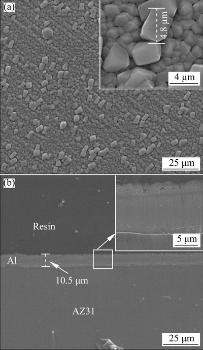
Fig. 1 Surface (a) and cross-sectional (b) morphologies of magnetron-sputtered Al layer
3.2 PEO-treated coatings
The cell potential-time responses during PEO of the Al-coated AZ31 alloy in a solution of 16 g/L Na2SiO3��9H2O and 32 g/L NaAlO2 are presented in Fig. 2. The potentials are peak values. The positive potential of the specimen in silicate electrolyte shows a rapid increase to the inflexion point of ~412 V at 16 s, after which the potential rises slowly toward a final value of 520 V at 600 s. In contrast, the positive potential in the aluminate electrolyte surges more rapidly to ~374 V at 7 s, after which it was maintained at nearly the same level to ~22 s, and then rose with increased rate to a high value of ~435 V at 147 s. After that time point, the cell potential dropped suddenly to 391 V, followed by a steadily recovery to ~455 V at 252 s, and then a fast decreasing to lower values. PEO in the aluminate electrolyte was terminated at 300 s with a final potential of ~337 V. Hence, the positive potential shows a complicated behavior in the aluminate electrolyte. Similar behaviors have been observed in a previous study on Al-covered Ti-6Al-4V alloy [35]. A careful observation of the PEO process at the later stage with a potential drop indicated that electrolyte has infiltrated into the crevices between the sample edges and the sealing resin, as can be inferred from the faint sparks in the crevices. The drop of the potential is possibly due to the newly exposed metal surface in the crevices, which has not yet been covered by high resistance oxide. The oxidation of the non-working areas is undesirable, but we have not yet a good way to prevent it. The negative potentials, which are lower than positive ones, also show an initial rapid growth.
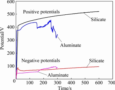
Fig. 2 Cell potential-time responses for PEO of Al- coated AZ31 magnesium alloy in 16 g/L Na2SiO3��9H2O+1 g/L KOH and 32 g/L NaAlO2+1 g/L KOH, respectively (The potentials are respectively positive and negative (absolute value) peak values for the potential pulses)
3.3 XRD patterns
The phase compositions of the coatings formed on the Al-coated samples in silicate and aluminate electrolytes were examined by XRD (Fig. 3). Peaks of Mg and Al, which come from the underlying substrate and Al layer, respectively, are evident in the XRD spectra. For the coating formed in aluminate electrolyte, both ��-Al2O3 and ��-Al2O3 are present as the main phases. However, only ��-Al2O3 is detected for the silicate coating. According to our previous studies, aluminate electrolyte favors the formation of ��-Al2O3 in the PEO coatings [34,35]. In contrast, the predominance of ��-Al2O3 phase in the coating formed in the silicate electrolyte may be due to the fact that silicon species can suppress the formation of ��-Al2O3. GULEC et al [37] found that when the Si content in a binary Al-Si alloy is higher than 2 at.%, ��-Al2O3 cannot be formed in the PEO coatings. In our previous study [16] of the PEO of a cast Al-Si alloy, ��-Al2O3 is also the predominant phase despite the use of aluminate-based electrolytes. The silicon in the present coatings comes from the electrolyte; however, regardless of its origin, the presence of Si in the coating, adversely affects ��-Al2O3 to ��-Al2O3 phase transformation [37]. High content of hard ��-Al2O3 phase is beneficial to improving wear resistance of the coatings [34,38].
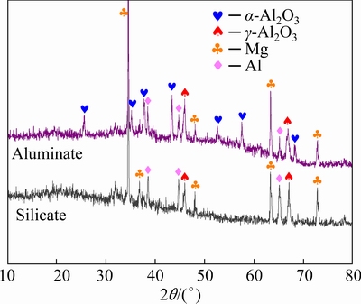
Fig. 3 XRD patterns of Al-coated AZ31 Mg alloy after being PEO-treated for different time in aluminate and silicate electrolytes, respectively
3.4 Morphologies of PEO-treated samples
Figure 4 shows the morphologies of surface and cross-section of the coating formed in 16 g/L Na2SiO3 solution for 600 s. A porous coating with pancake structures and fine particles is formed (see Fig. 4(a)). The pancake structure is typical in PEO coatings, which is thought to be generated by the penetrating discharges that reach the substrate [5,23,39]. The fine particles, proved to contain silicon by EDS, are the result of decomposition of electrolyte by discharges on the coating surface. Figure 4(b) displays the cross- section of the coating, showing a bi-layered structure. The image reveals a non-uniform coating with thickness between 21 and 32 ��m. Correspondingly, the interface of coating/Al is presented in the form of an undulating curve. Big and transverse pores with different sizes are found between the outer and inner layers. Under big pores, the coating/Al interface recedes toward the metal side, which means the consumption of more Al layer at these locations, possibly assisted by the plasma discharges. According to the discharge model presented in Ref. [5], the strong penetrating discharges caused the pancake structures and the underlying big pores. The inset in Fig. 4(b) shows a barrier layer at the coating/Al interface. It is believed that the barrier layer affords main protection during the corrosion processes [40-43]. Figure 4(c) shows EDS line scan spectra along the cross-section of the coating. Si content is mainly distributed at the outer layer. Figure 4(d) shows that the coating exclusively consists of elements of O, Al and Si.
The morphologies of the coating generated in 32 g/L NaAlO2 solution for 300 s are shown in Fig. 5. This coating is featured by irregular nodules and fine pores. The pancakes are absent. Furthermore, the cross-section (Fig. 5(b)) shows that the aluminate coating is dense and single- layered, with a thickness of ~28 ��m. The coating/Al layer interface is nearly parallel to the horizontal direction, which is different from the undulating interface in the silicate coating. Figures 5(c, d) show the EDS line scan spectra along cross- section and the point analysis on the coating surface, respectively. The elements of Al and O distribute uniformly along the coating depth. According to our previous study [15], the single-layered coating is attributed to the fact that type A or C discharges dominate the coating formation process in concentrated electrolyte. Type A or C discharges are weaker than the strong B type penetrating discharges which cause the pancake structures. Type A and C discharges occurred at the coating upper layer or the coating/electrolyte interface, resulting in thermal decomposition of aluminate anions into solid phase of Al2O3 [15,23]. The flat coating/Al interface may also indicate that the strong penetrating discharges are absent in this case.
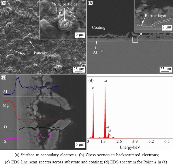
Fig. 4 Morphologies (a, b) and EDS spectra (c, d) of surface and cross-section of coating formed in 16 g/L Na2SiO3 solution for 600 s
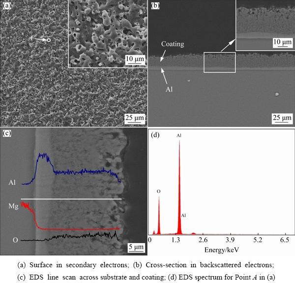
Fig. 5 Morphologies and EDS spectra of surface and cross-section of coating formed in 32 g/L NaAlO2 solution for 300 s
3.5 Microhardness and tribological properties
The microhardness of coatings formed in the silicate and aluminate electrolytes respectively has been measured. Figure 6 shows the microhardness indents on the cross-sections of the coatings after the tests. Figure 6(a) shows a small sized indent with a hardness value of HV 1401 at the outer layer of the silicate coating. However, the inner layer shows a lower hardness value of HV 643. An average value of HV (579��119) is obtained from 4 points made on the inner layer. The higher hardness of the outer layer is due to its compactness, as suggested by the SEM. Figure 6(b) displays some of the indents on the aluminate coating. An average hardness value of HV (1473��223) is obtained from 6 points, with the highest and lowest of hardness values of HV 1759 and 1060, respectively. The results show that the hardness of the aluminate coating is higher than that of silicate coating, which might be attributed to the high fraction of ��-Al2O3 in the former.
Friction coefficient as a function of sliding time was registered for the wear tests of the Al-coated AZ31 Mg alloy and the PEO coatings. Figure 7(a) shows the variations of the coefficient of friction for a sliding time of 1800 s under a load of 10 N. All of the samples show a similar friction coefficient of ~0.36 at 0 s. However, the coefficient of friction of the Al-coated sample decreases slightly at the initial stage, reaching ~0.29 at 72 s, after which it is kept at a relatively constant low level, with values between ~0.29 and 0.40. The coefficient of friction of the aluminate coating rises to ~0.47 at 150 s, and then it fluctuates in a range between ~0.41 and ~0.50. The coefficient of friction of the silicate coating rises to the highest value of ~0.53 at 160 s, after which it varies between ~0.50 and ~0.66, with repeated fluctuations. The fluctuations may be caused by the repeated entrapment and removal of the wear debris during the sliding process. Visual observation showed that the magnetron-sputtered Al layer was destroyed quickly after the application of load on the specimen and a deep trench was formed after the wear test. However, the PEO coatings exhibited excellent wear protection during the sliding tests under 10 N, with no signs of coating failure being observed during the tests. Figure 7(b) shows the corresponding profiles of wear scars after the dry sliding wear. The wear depths on the Al-coated specimen, the silicate coating and aluminate coating are ~145.5, 19.2 and 19.3 ��m, respectively. The results show that the PEO coatings have significantly protected the underlying Mg substrate under a moderate load of 10 N.
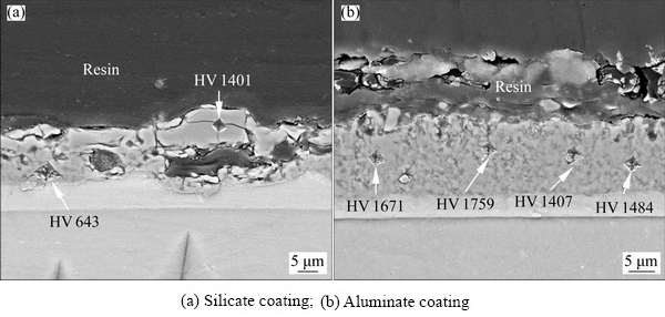
Fig. 6 SEM images showing indents on cross-sections of different samples after microhardness tests
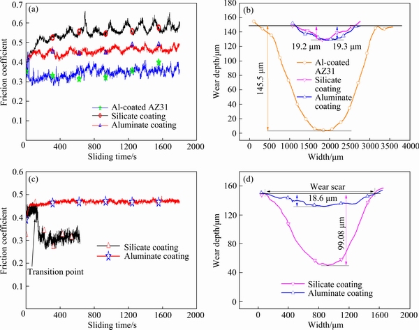
Fig. 7 Friction coefficient as function of sliding time (a) and wear depth profiles (b) after dry sliding under 10 N for Al-coated AZ31 and duplex PEO/Al samples formed in silicate and aluminate electrolytes, respectively, and friction coefficient as function of sliding time (c) and corresponding wear depth profiles (d) under 20 N for duplex PEO/Al samples formed in silicate and aluminate electrolytes, respectively
Dry sliding tests were also carried out under a higher load of 20 N. Figure 7(c) shows the variation of the friction coefficient during the tests. The silicate coating displays an initial stable period up to ~133 s, with the coefficient of friction between ~0.41 and 0.46. After that the coefficient of friction decreases quickly to 0.28 at 163 s, and then remains at ~0.26 to ~0.36. The point at which the coefficient of friction began to drop is marked as ��transition point��, which means that the coating was destroyed by steel ball and the sliding scenario changed into a mode of steel ball against metal substrate [44]. As a result, the coefficient of friction is close to that of the Al-coated specimen under a load of 10 N. The dry sliding test for the silicate coating was terminated at 600 s, since the specimen was heavily worn. However, no ��transition point�� was observed during the dry sliding of the steel ball against the aluminate coating. The coefficient of friction was kept at a constant level of ~0.47 till the end of 1800 s. Furthermore, the curve of coefficient of friction is smoother than that at 10 N, which may indicate the easy removal of wear debris. Figure 7(d) shows the wear scar profiles after the dry sliding tests under 20 N. The silicate coating was destroyed under 20 N, showing ~99.1 ��m wear depth after 600 s dry sliding. In contrast, the wear depth on the aluminate coating was only 18.6 ��m after 1800 s dry sliding. The later is even shallower than that formed under 10 N.
SEM images of the corresponding wear scars on different samples are shown in Fig. 8. Figures 8(a, b) show the wear scars on the Al- coated Mg alloy after 1800 s dry sliding test under 10 N. According to Fig. 8(a), a wear scar with a width of ~2.35 mm was formed on the sample surface. The magnified image in Fig. 8(b) shows long grooves parallel to the sliding direction, indicating abrasive wear [31]. The EDS analysis of Point A in Fig. 8(b) shows 96.1 wt.% Mg, 2.1 wt.% Al and 1.2 wt.% O, which confirms the exposure of the substrate. Figure 8(c) shows the wear scar on the silicate coating after 1800 s dry sliding test under 10 N. The width of wear scar is ~1.59 mm, which is narrower than that on the Al-coated sample. Figure 8(d) shows the boxed region in Fig. 8(c). The out layer of the coating has been removed. Smooth patches with irregular shapes exist in the wear track. The EDS analysis of one of the patches (Point B in Fig. 8(d)) shows the composition of 39.0 wt.% O, 43.0 wt.% Al, 5.8 wt.% Si, 11.5 wt.% Fe and 0.68 wt.% Mg, respectively. The element from the sliding counterpart (Fe) demonstrates the formation of ��transfer layer�� or ��tribolayer�� [44-46]. Transfer layers were formed by tribo-oxidation of the steel counterface, due to the combined actions of mechanical stresses and frictional heating [44]. The wear scar on the aluminate coating after 1800 s dry sliding under 10 N displays the narrowest width of ~1.41 mm (Fig. 8(e)). Furthermore, the transfer layers are more evident in this case (see Fig. 8(f)). The EDS analysis of Point C on the transfer layer in Fig. 8(f) reveals only the elements of Fe and O (74.9 wt.% Fe and 25.0 wt.%). The result shows that more materials from the steel ball have been incorporated into the transfer layer, suggesting a higher hardness of the aluminate coating. Figures 8(g-i) show the wear scar morphologies under 20 N. The wear scar on the aluminate coating is similar to that under 10 N, showing a width of ~1.43 mm (Fig. 8(g)). Transfer layers were also formed on the wear scar under 20 N (see Fig. 8(h)). EDS analysis of the wear track (Point D) shows the presence of O, Al and Fe, which are elements from the coating and steel ball, respectively. The silicate coating has been completely destroyed under the load of 20 N. A wide wear scar (~2.41 mm) with long grooves parallel to sliding direction is shown in the SEM image (Fig. 8(i)). EDS analysis at Point E shows only the elements of substrate. The long grooves indicate the mechanism of abrasive wear.
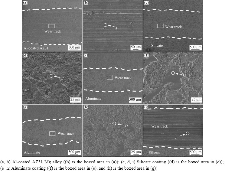
Fig. 8 SEM images of wear scars on different samples after dry sliding wear tests under 10 N (a-f) and 20 N (g-i)
The results presented here indicate that the combined treatment of magnetron sputtering and PEO can significantly improve the wear resistance of AZ31 magnesium alloy. Moreover, PEO coatings formed in aluminate are superior to the coatings formed in silicate electrolyte, especially under the increased load of 20 N. The big internal pores in the silicate coating (see Fig. 4(b)) may be the reason associated with the lowered wear performance, since the outer part of the coating may be easily damaged under the higher load [15,34,47]. In contrast, the single layered structures [34], along with the higher fraction of ��-Al2O3 and the higher hardness, are reasons for the excellent performance of the present aluminate coatings.
3.6 Corrosion behavior
3.6.1 Polarization curves
Potentiodynamic polarization measurements for different samples were performed after 1 h immersion in 3.5 wt.% NaCl. Figure 9 shows the results. The un-treated magnesium AZ31 alloy shows the behavior of a typical active material. A sharp increase in anodic current density is observed for small potential variation above the corrosion potential of -1.544 V (vs SCE). For the Al-coated AZ31 Mg alloy, a more negative corrosion potential of -1.687 V (vs SCE) was recorded during the polarization process. With the potential rise, the curve shows a vertical passive region (from -1.60 to -0.76 V (vs SCE)). After that, a turning point occurs at -0.744 V (vs SCE), which is the breakdown potential. The occurrence of passive region indicates that the surface property of the Mg alloy has been drastically modified after the magnetron sputtering of Al. It actually displays the behavior of magnetron-sputtered Al. The polarization curves of the Al-coated AZ31 after PEO treatments are also presented. The corrosion potential of the PEO coatings moves to positive position compared to that of the Al-coated AZ31 alloy. The silicate coating does not show an obvious passive region in the anodic branch of the curve. However, the aluminate coating exhibits a region of extended passivity, with low current densities until the end of the test. The parameters obtained from polarization curve are listed in Table 1, where the free corrosion current densities (Jcorr) were obtained by Tafel extrapolation method. According to Table 1, the AZ31 alloy shows the largest Jcorr with a value of 7.5��10-3 A/cm2, and the Jcorr of Al-coated alloy is one order less than that of the un-coated AZ31 alloy. Moreover, values of Jcorr of the coatings formed in silicate and aluminate solutions are two orders of magnitude lower than that of Al-coated AZ31 alloy, implying that the PEO treatments have significantly improved the corrosion resistance of the treated alloy.
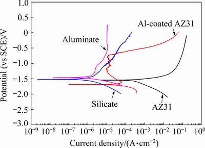
Fig. 9 Potentiodynamic polarization curves for different samples after immersion in 3.5 wt.% NaCl solution for 1 h
Table 1 Electrochemical data extracted from Fig. 9

3.6.2 Immersion test results and OCP evolution
During the corrosion process, OCPs were determined by the balance between the anodic and cathodic reactions on the surface of the tested samples. Hence, the variation of OCP can reveal the information about the corrosion process [48]. Figure 10(a) shows variation of OCPs up to 5 h immersion in 3.5 wt.% NaCl solution for pure Al, un-coated AZ31 Mg alloy, Al-coated AZ31, and the Al-coated AZ31samples following PEO treatments in silicate and aluminate electrolytes, respectively. Figure 10(b) shows the OCPs between 0 and 300 s. Pure Al is introduced for comparison. It is shown that the pure Al exhibits the highest OCP values between -1.1 and -0.9 V (vs SCE), while the AZ31 alloy shows the lowest values of ~ -1.6 V (vs SCE). The OCP of Al-coated AZ31 alloy is close to that of pure Al at the initial 0-18 s; however, it decreases quickly to ~ -1.462 V (vs SCE) at 108 s, after which it was kept at lower values between -1.54 and -1.36 V (vs SCE). The fast decrease of OCP toward negative position may be due to the permeation of electrolyte into the interior of the magnetron-sputtered layer. Furthermore, fine gas bubbles and corrosion pits can be observed on the surface of the Al-coated AZ31 after a very short immersion time of 1-2 min. These results indicate that the magnetron-sputtered Al layer cannot afford sufficient protection to the substrate and the electrolyte can reach the Al/Mg interface quickly. The permeation of the electrolyte may be through the paths between the grain boundaries, which are clearly seen from the sample surface in the inset of Fig. 1(a). The presence of gaps between the grain boundaries further facilitates fast ingress of the corrosion medium. The OCP curves of the PEO-treated samples are kept at stable values around -1.4 V (vs SCE) up to 300 s, except for an initial drop from -1.30 to ~ -1.42 V (vs SCE) between 0 and ~13 s for the aluminate coating. After that, the OCP curves decrease slowly towards the final values of -1.495 and -1.507 V (vs SCE) for the aluminate and silicate coatings, respectively. In most time of the immersion, the OCP of the aluminate coating is nobler than that of the silicate coating, which may imply better corrosion protection of the former.
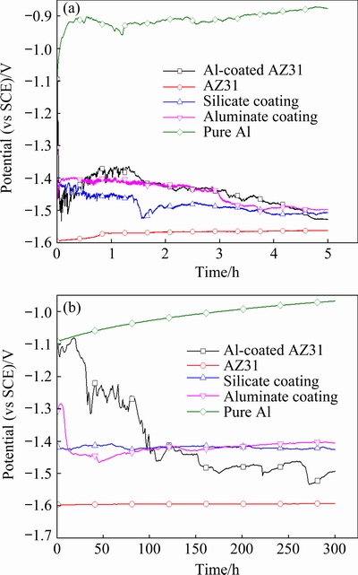
Fig. 10 OCP curves of different samples during immersion in 3.5 wt.% NaCl solution for 5 h (a) and the first 300 s (b)
Figure 11 shows the optical appearances of different samples after immersion for 5 h in the 3.5 wt.% NaCl solution. The surface of AZ31 has been completely corroded after the immersion test. The Al-coated AZ31 is also seriously corroded, revealing large areas of exposed substrate. PEO treatments have significantly improved the corrosion resistance of the samples. The sample coated by silicate coating is almost intact; however, two pits are observed at the lower part of the sample, indicating localized corrosion. The aluminate coating shows the best protection to the AZ31 substrate, without any signs of corrosion on the surface.
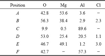
The samples after 5 h immersion have been examined by SEM and EDS. The results are shown in Fig. 12 and Table 2, respectively. Figure 12(a) shows the surface morphology of AZ31 magnesium alloy after the immersion test, which is featured by cracks and mud-like material. The EDS of Point A in Fig. 12(a) reveals the composition of O, Mg, and Al, with the former two elements as the main components. Figure 12(b) shows a broken region on the Al-coated AZ31 sample. This region corresponds to one of the small pits on this sample in Fig. 11. The previous magnetron-sputtered Al layer is almost lost; however, a small piece of curled Al layer is still attached on the edge of the broken region. The curled Al-layer is possibly pushed up by the hydrogen evolution during the corrosion process. EDS analysis shows that the material inside the broken region is the corrosion product of the substrate (Point B in Table 2). Figure 12(c) shows the details of the boxed area in Fig. 12(b). The area is close to the edge of the broken region. The grains of the magnetron- sputtered Al can still be seen on the surface; however, most parts of the surface are covered by a layer of corrosion product, as revealed by the EDS analysis of Point D (53.0 wt.% O, 25.4 wt.% Mg, 20.5 wt.% Al and 1.1 wt.% Cl). The layer of corrosion product might be the precipitates of Mg(OH)2 and Al(OH)3, which are formed by the reactions between OH- and the cations of Mg2+ and Al3+, with their origin from the nearby corroded region. Figure 12(d) shows the low magnification image of a corrosion pit on the silicate coating. The pit is irregularly shaped, with a size of ~400 ��m. Figure 12(e) shows the details of the boxed area in Fig. 12(d). Plate-like corrosion products separated by cracks are seen in the bottom of the pit. The composition of the corrosion product is 46.7 wt.% O, 49.1 wt.% Mg, 1.2 wt.% Al, and 3.0 wt.% Cl. At the periphery of the corrosion pit, however, coating is kept at its original morphology, with pancake microstructures being observed. Figure 12(f) shows the morphology of the aluminate coating after 5 h immersion. No changes in coating morphology and composition have been detected after the immersion test.
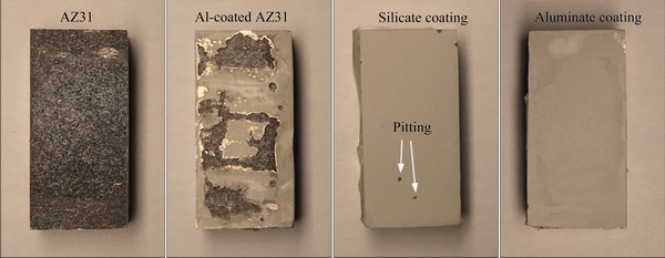
Fig. 11 Optical appearances of different samples after 5 h immersion in 3.5 wt.% NaCl solution (The size of samples is 10 mm �� 20 mm)
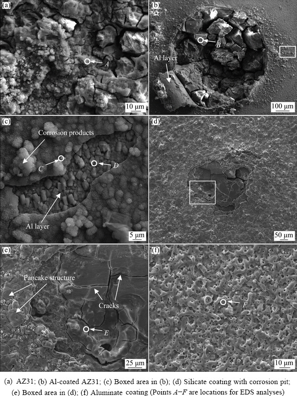
Fig. 12 SEM images of surface of different samples after 5 h immersion in 3.5 wt.% NaCl solution
Table 2 EDS results of positions in Fig. 12 (wt.%)
3.6.3 EIS data
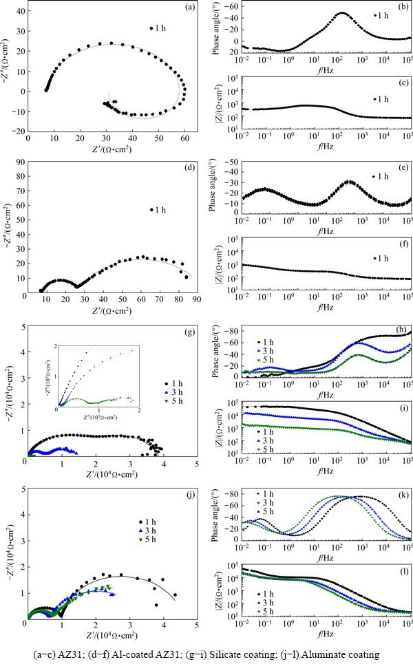
Fig. 13 Nyquist and Bode plots recorded for different samples during different stages of immersion in 3.5 wt.% NaCl solution
EIS was used widely to evaluate the corrosion behaviour of PEO coatings [49,50]. EIS data of the AZ31 substrate, Al-coated AZ31, and the aluminate and silicate coatings (PEO/Al duplex samples) are recorded as a function of immersion time in 3.5 wt.% NaCl solution. Figures 13(a-c) show the Nyquist and Bode plots of the un-coated AZ31 after immersion for 1 h. A capacitive loop and an inductive loop are clearly seen in the Nyquist plot. The Bode phase angle plot shows a peak in medium frequency range, corresponding to a time constant. The EIS spectra of the un-coated AZ31 are similar to those of Mg alloys reported in Refs. [51-53]. The inductive loop in the low frequency range is believed to be associated with pitting corrosion of substrate [54-56].
Figures 13(d-f) show the EIS spectra of the Al-coated AZ31, which are different from those of the un-coated sample. Two capacitive loops can be identified from the Nyquist plot in Fig. 13(d). Figure 13(e) reflects two time constants in low and high frequency ranges, respectively. Figure 13(f) shows the Bode modulus plot. Compared with the un-coated sample, the modulus of the Al-coated sample at low frequency increases slightly, but it is still in the same order of magnitude. The result indicates that corrosion protection provided by the magnetron-sputtered Al is limited.
Figures 13(g-i) show the EIS spectra of the silicate coating after 1, 3 and 5 h immersion. After 1 h immersion, the Nyquist plot consists of two capacitive loops in the same size that are almost overlapped (Fig. 13(g)). Figure 13(i) shows that the modulus of impedance has been greatly improved, reaching ~3.4��104 ����cm2 at low frequencies. After 3 h immersion, two capacitive loops with different diameters can be identified from Fig. 13(g). A new time constant appears in low frequency range in Fig. 13(h), which is different from the result after 1 h immersion. The reduction of diameter of capacitive loops, the appearance of new time constant and the decrease of impedance modulus imply that the structure of PEO coating may be changed. After 5 h immersion, the capacitive loops can only be distinguished from enlarged image and their diameters are reduced to the minimum.
Figures 13(j-l) present the EIS spectra of the aluminate coating after 1, 3 and 5 h immersion. In Fig. 13(j), all the EIS spectra show two capacitive loops, which correspond to the two time constants at high and low frequencies respectively in Fig. 13(k). The modulus of impedance at low frequencies reaches ~4.3��104 ����cm2 after 1 h immersion, which is higher than that of the silicate coating. Moreover, the modulus at low frequencies only decreases slightly when the immersion time is extended to 3 and 5 h.
Owing to different physical characteristics of the samples and different corrosion stages, different electrical equivalent circuits (EECs) should be used to fit the EIS spectra. Figure 14 presents the EECs used in this study and Table 3 lists the fitted parameters. The solid lines in Fig. 13 are the fitted results, which match well with the original data points. The ECC in Fig. 14(a) is used for fitting the EIS of the AZ31 Mg alloy. This ECC has been widely used to fit the EIS recorded during the corrosion of Mg alloys [54,55,57]. The equivalent elements are as follows: Rs is the solution resistance; R1 and CPE1 represent the charge transfer resistance and the double layer capacitance at the electrolyte and AZ31 substrate interface, respectively; RL and L1 are parameters associated with the inductive loop caused by pitting of Mg alloy [57].
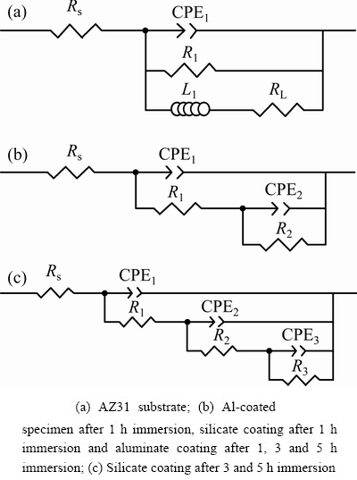
Fig. 14 Electrical equivalent circuits used to fit EIS spectra in Fig. 13
The EEC circuit in Fig. 14(b) was used to fit the EIS spectra of the Al-coated AZ31. In this case, Rs is also the solution resistance, R1 and CPE1 correspond to the pore resistance and capacitance of the Al layer, respectively, R2 and CPE2 denote the charge transfer resistance and double-layer capacitance at the interface between Al layer and AZ31 substrate, respectively. According to Table 3, the value of R2 is 66 ����cm2. Compared with the charge transfer resistance of un-coated AZ31 substrate (52 ����cm2), the value only increases slightly, which demonstrates that the magnetron sputtered layer cannot provide sufficient protection to the substrate.
Table 3 Fitted equivalent circuit parameters obtained from EIS
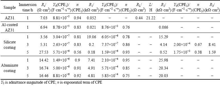
In the case of silicate coating, the circuit in Fig. 14(b) is also used to fit the EIS result after 1 h immersion. Other authors also used the same circuit to describe the corrosion process of the PEO coatings [42,58,59]. At this time, Rs represents the solution resistance, the same as before. However, R1 and CPE1 correspond to the pore resistance and capacitance of the outer layer, respectively, R2 and CPE2 represent the resistance and capacitance of the barrier layer, respectively. The microstructure of the coating at this stage is illustrated in Fig. 15(a1), which indicates that electrolyte has just penetrated into the pores and cracks of the outer layer. The values of R1 and R2 as shown in Table 3 are ~19 and ~15 k����cm2, respectively, illustrating that the outer layer and the barrier layer contribute nearly equally to the corrosion resistance at early corrosion stage. The EIS spectra of the silicate coating after 3 and 5 h immersion are fitted with the equivalent circuit in Fig. 14(c). Figures 15(a2-a3) illustrate the corresponding coating microstructures. The emergence of a new time constant in the EIS spectra indicates that the electrolyte has reached the PEO coating/Al layer interface (see Fig. 15(a2)). After 5 h immersion, electrolyte channels expanded within the Al layer, leading to further damage of the PEO coating (Fig. 15(a3)). The R1, CPE1 and R2, CPE2 in the equivalent circuit correspond to the contribution from the outer and the barrier layers, respectively. R3 and CPE3 represent the resistance and capacitance of the Al layer, respectively. According to Table 3, the values of R1, R2 and R3 at 3 h are 0.2, ~4.1 and ~8.4 k����cm2, respectively. The results show that the outer layer is seriously damaged and corrosion resistance is mainly offered by the barrier layer and Al layer. After 5 h immersion, the values of R1, R2 and R3 are further reduced to lower levels. The resistance of Al layer (R3) became ~1.6 k����cm2, which is only ~1/5 of the value at 3 h.
All the EIS results of aluminate coating can be fitted by the circuit in Fig. 14(b). The coating microstructure at different stages of immersion is depicted in Figs. 15(b1-b3). The PEO coating consists of the outer porous layer and the dense inner layer (see Fig. 5). According to the illustration, the electrolyte entered the small pores and cracks in the outer layer at Stage 1, and reached the outer part of the inner layer at Stages 2 and 3. However, the electrolyte has not reached the Al layer at the longest immersion time of 5 h. In this case, Rs is the resistance of solution, R1 and CPE1 are related to the pore resistance and capacitance of the outer layer, respectively, R2 and CPE2 correspond to the inner layer, respectively. After 1 h immersion, the values of R1 and R2 are ~7.4 and ~26 k����cm2, respectively. The higher value of R2 is due to a denser inner layer which provides better corrosion resistance. The values of R1 and R2 decrease to ~4.9 and ~20.3 k����cm2, respectively after 3 h immersion. The change in the resistances implies the penetration of electrolyte deeper into inner layer and a decrease of the corrosion resistance. After 5 h immersion, the values of R1 and R2 are ~4.8 and ~20 k����cm2, respectively, which are only slightly lower than the previous values and are much greater than those of the silicate coating. All these results indicate the superior corrosion resistance of the aluminate coating.
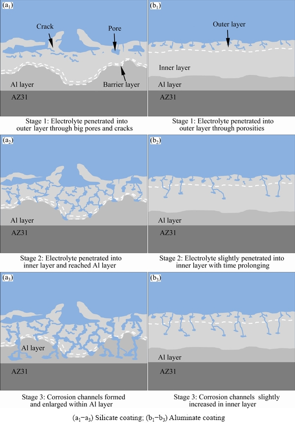
Fig. 15 Schematic diagrams of corrosion of silicate and aluminate coatings in 3.5 wt.% NaCl solution for 1 h (a1, b1), 3 h (a2, b2) and 5 h (a3, b3)
4 Discussion
This study tried to improve the wear and corrosion performance of AZ31 magnesium alloy by a combined method of magnetron sputtering and PEO. The results in this work reveal that the magnetron sputtering method alone cannot afford a reasonable protection to the substrate, both from the point of view of wear and corrosion. This is not unexpected since the magnetron-sputtered Al layer is thin and full of defects such as the grain boundaries. Corrosive species can easily penetrate the Al layer, leading to the corrosion of Mg substrate. Furthermore, galvanic couple will be formed between the active Mg substrate and the Al layer. The formation of galvanic couple will further deteriorate the corrosion performance.
PEO treatments following the magnetron sputtering greatly improved the wear performance of the AZ31 samples. The aluminate electrolyte is more effective in generating wear-resistance coatings. The superior wear performance can be attributed to the single layered nature of the coating formed in the aluminate electrolyte [34,35]. Moreover, the higher fraction of corundum phase (��-Al2O3) is also helpful for the wear performance of the coating; however, it is not as decisive as the microstructure [35].
The aluminate coating also shows better corrosion protection to the AZ31 substrate than the silicate coating. The big pores and cracks in the microstructure of the silicate coating are detrimental to its corrosion resistance. It should be noted that the combined method of magnetron sputtering and PEO does not improve the corrosion performance as effectively as improving the wear resistance. The aluminate coating shows excellent corrosion protection to the AZ31 substrate for immersion time up to 5 h. However, the aluminate coating will be destroyed after immersion for 24 h. This is due to the easy penetration of the corrosive Cl�C ions with small atomic radius into the inner coating. Further investigation to improve the corrosion resistance will be focused on the post treatment methods such as the sealing treatment based on cerium salt [60].
5 Conclusions
(1) The combined method of magnetron sputtering and PEO has significantly improved the wear performance of the AZ31 Mg alloy. Under the load of 10 N, both the PEO coatings formed in silicate and aluminate electrolytes show good wear resistance, exhibiting low wear depth of ~19.2 and 19.3 ��m, for the silicate and aluminate coatings, respectively. However, only the aluminate coating protected the underlying alloy at the increased load of 20 N. The reason is attributed to the higher content of ��-Al2O3 of the coating formed in aluminate electrolyte.
(2) The magnetron-sputtered Al layer cannot afford sufficient protection to the AZ31 Mg alloy. The grain boundaries and defects in the magnetron- sputtered layer provided fast routs for the easy penetration of the corrosive species, leading to pitting corrosion.
(3) PEO treatment greatly reduced the Jcorr of Al-coated specimen. Meanwhile, immersion tests and EIS analysis indicate that the aluminate coating showed better short-term corrosion protection than the silicate coating. The lower corrosion protection of the silicate coating is due to the large pores and other defects in the microstructure. The more homogenous microstructure of the aluminate coating increases its corrosion resistance.
Acknowledgments
The authors thank the National Natural Science Foundation of China (No. 51671084).
References
[1] PEZZATO L, BRUNELLI K, NAPOLITANI E, MAGRINI M, DABALA M. Surface properties of AZ91 magnesium alloy after PEO treatment using molybdate salts and low current densities [J]. Applied Surface Science, 2015, 357: 1031-1039.
[2] HUSSEIN R O, NORTHWOOD D O, NIE X. The influence of pulse timing and current mode on the microstructure and corrosion behaviour of a plasma electrolytic oxidation (PEO) coated AM60B magnesium alloy [J]. Journal of Alloys and Compounds, 2012, 541: 41-48.
[3] BARCHICHE C E, ROCCA E, JUERS C, HAZAN J, STEINMETZ J. Corrosion resistance of plasma-anodized AZ91D magnesium alloy by electrochemical methods [J]. Electrochimica Acta, 2007, 53: 417-425.
[4] PADHEE C K, MASANTA M, MONDAL A K. Feasibility of Al-TiC coating on AZ91 magnesium alloy by TIG alloying method for tribological application [J]. Transactions Nonferrous Metals Society of China, 2020, 31: 1550-1559.
[5] TU Wen-bin, CHENG Yu-ling, WANG Xin-yao, ZHAN Ting-yan, HAN Jun-xiang, CHENG Ying-liang. Plasma electrolytic oxidation of AZ31 magnesium alloy in aluminate-tungstate electrolytes and the coatings formation mechanism [J]. Journal of Alloys and Compounds, 2017, 725: 199-216.
[6] HUSSEIN R O, NIE X, NORTHWOOD D O. An investigation of ceramic coating growth mechanisms in plasma electrolytic oxidation (PEO) processing [J]. Electrochimica Acta, 2013, 112: 111-119.
[7] ZHANG Rong-fa, ZHANG Su-fang. Formation of micro-arc oxidation coatings on AZ91HP magnesium alloys [J]. Corrosion Science, 2009, 51: 2820-2825.
[8] MAO Yan, LI Zhu-guo, FENG Kai, GUO Xing-guo, ZHOU Zhi-feng, WU Yi-xiong. Corrosion behavior of carbon film coated magnesium alloy with electroless plating nickel interlayer [J]. Journal of Materials Processing Technology, 2015, 219: 42-47.
[9] HAJIALI F M, AMADEH A. Improvement of wear and corrosion resistance of AZ91 magnesium alloy by applying Ni-SiC nanocomposite coating via pulse electrodeposition [J]. Transactions of Nonferrous Metals Society of China, 2013, 23: 2914-2922.
[10] ZHANG Rong-fa. Film formation in the second step of micro-arc oxidation on magnesium alloys [J]. Corrosion Science, 2010, 52: 1285-1290.
[11] GRAY J E, LUAN B. Protective coatings on magnesium and its alloys��A critical review [J]. Journal of Alloys and Compound, 2002, 336: 88-113.
[12] CHEN Y, LU X P, LAMAKA S V, JU P F, BLAWERT C, ZHANG T, WANG F H, ZHELUDKEVICH M L. Active protection of Mg alloy by composite PEO coating loaded with corrosion inhibitors [J]. Applied Surface Science, 2020, 504: 144462.
[13] ZHOU Qin-yi, TIAN Meng-meng, YING Zong-rong, DAN Yu-xin, TANG Feng-rui, ZHANG Jian-peng, ZHU Jun-wu, ZHU Xu-fei. Dense films formed during Ti anodization in NH4F electrolyte: Evidence against the field-assisted dissolution reactions of fluoride ions [J]. Electrochemistry Communications, 2020, 111: 106663.
[14] ZHANG Zhao-ying, WANG Qi, XU Hao-qing, ZHANG Wen-chao, ZHOU Qin-yi, ZENG Hui-peng, YANG Jia-lu, ZHU Jun-wu, ZHU Xu-fei. TiO2 nanotubes arrays with a volume expansion factor greater than 2.0: Evidence against the field-assisted ejection theory [J]. Electrochemistry Communications, 2020, 114: 106717.
[15] CHENG Y L, CAO J H, MAO M K, XIE H J, SKELDON P. Key factors determining the development of two morphologies of plasma electrolytic coatings on an Al-Cu-Li alloy in aluminate electrolytes [J]. Surface and Coatings Technology, 2016, 291: 239-249.
[16] XIE Huan-jun, CHENG Ying-liang, LI Shao-xiao, CAO Jin-hui, CAO Li. Wear and corrosion resistant coatings on surface of cast A356 aluminum alloy by plasma electrolytic oxidation in moderately concentrated aluminate electrolytes [J]. Transactions of Nonferrous Metals Society of China, 2017, 27: 336-351.
[17] AN Ling-yun, MA Ying, YAN Xiao-xu, WANG Sheng, WANG Zhan-ying. Effects of electrical parameters and their interactions on plasma electrolytic oxidation coatings on aluminum substrates [J]. Transactions of Nonferrous Metals Society of China, 2020, 30: 883-895.
[18] LU X P, BLAWERT C, TOLNAI D, SUBROTO T, KAINER K, ZHANG T, WANG F H, ZHELUDKEVICH M. 3D reconstruction of plasma electrolytic oxidation coatings on Mg alloy via synchrotron radiation tomography [J]. Corrosion Science, 2018, 139: 395-402.
[19] ZHANG R F, ZHANG S F, YANG N, YAO L J, HE F X, ZHOU Y P, XU X M, CHANG L R, BAI S J. Influence of 8-hydroxyquinoline on properties of anodic coatings obtained by micro arc oxidation on AZ91 magnesium alloys [J]. Journal of Alloys and Compounds, 2012, 539: 249-255.
[20] FATTAH-ALHOSSEINI A, CHAHARMAHALI R, BABAEI K. Effect of particles addition to solution of plasma electrolytic oxidation (PEO) on the properties of PEO coatings formed on magnesium and its alloys: A review [J]. Journal of Magnesium and Alloys, 2020, 3: 799-818.
[21] GAO Fang-yuan, HAO Li, LI Guang, XIA Yuan. The plasma electrolytic oxidation micro-discharge channel model and its microstructure characteristic based on Ti tracer [J]. Applied Surface Science, 2018, 431: 13-16.
[22] WEI Ke-jian, ZHANG Yi-fan, YU Jiao-hao, LIU Rui-hong, DU Jian-cheng, JIANG Fu-bin, XUE Wen-bin. Analyses of hydrogen release on Zirlo alloy anode during plasma electrolytic oxidation [J]. Materials Chemistry and Physics, 2020, 251: 123054.
[23] CHENG Ying-liang, WANG Ting, LI Shao-xian, CHENG Yu-lin, CAO Jin-hui, XIE Huan-jun. The effects of anion deposition and negative pulse on the behaviors of plasma electrolytic oxidation (PEO)��A systematic study of the PEO of a Zirlo alloy in aluminate electrolytes [J]. Electrochimica Acta, 2017, 225: 47-68.
[24] CHENG Y L, ZHANG Q H, ZHU Z D, TU W B, CHENG Y L, SKELDON P. Potential and morphological transitions during bipolar plasma electrolytic oxidation of tantalum in silicate electrolyte [J]. Ceramics International, 2020, 46: 13385-13396.
[25] CHENG Yu-lin, ZHU Zhun-da, ZHANG Qing-he, CHENG Ying-liang. Plasma electrolytic oxidation of brass [J]. Surface and Coatings Technology, 2020, 385: 125366.
[26] CLYNE T W, TROUGHTON S C. A review of recent work on discharge characteristics during plasma electrolytic oxidation of various metals [J]. International Materials Review, 2019, 64: 127-162.
[27] GU Wei-chao, SHEN De-jiu, WANG Yu-lin, CHEN Guang-liang, FENG Wen-ran, ZHANG Gu-ling, FAN Song-hua, LIU Chi-zi, YANG Si-ze. Deposition of duplex Al2O3/aluminum coatings on steel using a combined technique of arc spraying and plasma electrolytic oxidation [J]. Applied Surface Science, 2006, 252: 2927-2932.
[28] GU Wei-chao, LV Guo-hua, CHEN huan, CHEN Guang- liang, FENG Wen-ran, ZHANG Gu-ling, YANG Si-ze. Preparation of ceramic coatings on inner surface of steel tubes using a combined technique of hot-dipping and plasma electrolytic oxidation [J]. Journal of Alloys and Compounds, 2007, 430: 308-312.
[29] ZHANG P, NIE X Y, NORTHWOOD D O. Influence of coating thickness on the galvanic corrosion properties of Mg oxide in an engine coolant [J]. Surface and Coatings Technology, 2009, 203: 3271-3277.
[30] YU Lu, CAO Jin-hui, CHENG Ying-liang. An improvement of the wear and corrosion resistances of AZ31 magnesium alloy by plasma electrolytic oxidation in a silicate- hexametaphosphate electrolyte with the suspension of SiC nanoparticles [J]. Surface and Coatings Technology, 2015, 276: 266-278.
[31] SRINIVASAN P B, LIANG J, BLAWERT C, DIETZEL W. Dry sliding wear behaviour of magnesium oxide and zirconium oxide plasma electrolytic oxidation coated magnesium alloy [J]. Applied Surface Science, 2010, 256: 3265-3273.
[32] LIANG Jun, HU Li-tian, HAO Jing-cheng. Characterization of microarc oxidation coatings formed on AM60B magnesium alloy in silicate and phosphate electrolytes [J]. Applied Surface Science, 2007, 253: 4490-4496.
[33] LOU B S, LEE J W, TSENG C M, LIN Y Y, YEN C A. Mechanical property and corrosion resistance evaluation of AZ31 magnesium alloys by plasma electrolytic oxidation treatment: Effect of MoS2 particle addition [J]. Surface and Coatings Technology, 2018, 350: 813-822.
[34] CHENG Y L, CAO J H, MAO M K, PENG Z M, SKELDON P, Thompson G E. High growth rate, wear resistant coatings on an Al-Cu-Li alloy by plasma electrolytic oxidation in concentrated aluminate electrolytes [J]. Surface and Coatings Technology, 2015, 269: 74-82.
[35] KANG Shi-hang, TU Wen-bin, HAN Jun-xiang, LI Zhi, CHENG Ying-liang. A significant improvement of the wear resistance of Ti6Al4V alloy by a combined method of magnetron sputtering and plasma electrolytic oxidation (PEO) [J]. Surface and Coatings Technology, 2019, 358: 879-890.
[36] WANG Xing-yu. The preparation technology, microstructure and property of Al film deposited by magnetron sputtering on magnesium alloy [D]. Huhhot: Inner Mongolia University of Technology, 2017: 27-45.
[37] GULEC A E, GENCER Y, TARAKCI M. The characterization of oxide based ceramic coating synthesized on Al-Si binary alloys by micro arc oxidation [J]. Surface and Coatings Technology, 2015, 269: 100-107.
[38] MATYKINA E, ARRABAL R, MOHEDANO M, MINGO B, GONZALEZ J, PARDO A, MERINO M C. Recent advances in energy efficient PEO processing of aluminium alloys [J]. Transactions of Nonferrous Metals Society of China, 2017, 27: 1439-1454.
[39] CHENG Y L, WU F, MATYKINA E, SKELDON P, THOMPSON G E. The influences of micro-discharge types and silicate on the morphologies and phase compositions of plasma electrolytic oxidation coatings on Zircaloy-2 [J]. Corrosion Science, 2012, 59: 307-315.
[40] ZHU Li-ye, QIU Ji, CHEN Jin-hui, ZHANG Wei, CHEN Zhi-xiong, ZHANG Tao, WANG Fu-hui. Microstructure and corrosion resistance of the PEO coating on extruded Al6Cu alloy [J]. Surface and Coatings Technology, 2019, 369: 116-126.
[41] LIU Chen, LIU Peng, HUANG Zhi-quan, YAN Qin, GUO Ren-ge, LI Da-long, JIANG Gui-rong, SHEN De-jiu. The correlation between the coating structure and the corrosion behavior of the plasma electrolytic oxidation coating on aluminum [J]. Surface and Coatings Technology, 2016, 286: 223-230.
[42] DEHNAVI V, SHOESMITH D W, LUAN B L, YARI M, LIU X Y, ROHANI S. Corrosion properties of plasma electrolytic oxidation coatings on an aluminum alloy��The effect of the PEO process stage [J]. Materials Chemistry and Physics, 2015, 161: 49-58.
[43] MINGO B, ARRABAL R, MOHEDANO M, LLAMA- ZARES Y, MATYKINA E, YEROKIN A, PARDO A. Influence of sealing post-treatments on the corrosion resistance of PEO coated AZ91 magnesium alloy [J]. Applied Surface Science, 2018, 433: 653-667.
[44] MARTINI C, CESCHINI L, TARTERINI F, PAILLARD J M, CURRAN J A. PEO layers obtained from mixed aluminate-phosphate baths on Ti-6Al-4V: Dry sliding behavior and influence of a PTFE topcoat [J]. Wear, 2010, 269: 747-756.
[45] ARRABAL R, MOHEDANO M, MATYKINA E, PARDO A, MINGO B, MERINO M C. Characterization and wear behavior of PEO coatings on 6082-T6 aluminum alloy with incorporated ��-Al2O3 particles [J]. Surface and Coatings Technology, 2015, 269: 64-73.
[46] CHENG Y L, XUE Z G, WANG Q, WU X Q, MATYKINA E, SKELDON P, THOMPSON G E. New findings on properties of plasma electrolytic oxidation coatings from study of an Al-Cu-Li alloy [J]. Electrochimica Acta, 2013, 107: 358-378.
[47] CHENG Y L, CAO J H, PENG Z M, WANG Q, MATYKINA E, SKELDON P, THOMPSON G E. Wear-resistance coatings formed on Zircaloy-2 by plasma electrolytic oxidation in sodium aluminate electrolytes [J]. Electrochimica Acta, 2014, 116: 453-466.
[48] CHENG Ying-liang, MAO Mo-ke, CAO Jin-hui, PENG Zhao-mei. Plasma electrolytic oxidation of an Al-Cu-Li alloy in alkaline aluminate electrolytes: A competition between growth and dissolution for the initial ultra-thin films [J]. Electrochimica Acta, 2014, 138: 417-429.
[49] LU X P, BLAWERT C, HUANG Y D, OVRI H, ZHELUDKEVICH M L, KAINER K U. Plasma electrolytic oxidation coatings on Mg alloy with addition of SiO2 particles [J]. Electrochimica Acta, 2016, 187: 20-33.
[50] YANG J J, BLAWERT C, LAMAKA S V, SNIHIROVA D, LU X P, DI S C, ZHELUDKEVICH M L. Corrosion protection properties of inhibitor containing hybrid PEO- epoxy coating on magnesium [J]. Corrosion Science, 2018, 140: 99-110.
[51] WEI Xian, LIU Pin-duo, MA Su-jie, LI Zhi-cheng, PENG Xu-biao, DENG Rong-ping, ZHAO Qing. Improvement on corrosion resistance and biocompatibility of ZK60 magnesium alloy by carboxyl ion implantation [J]. Corrosion Science, 2020, 173: 108729.
[52] SUN Le, MA Ying, WANG Jin-song, AN Ling-yun, WANG Sheng, WANG Zhan-ying. Preparation and corrosion resistance of hybrid coatings formed by PEN/C plus PEO on AZ91D magnesium alloys [J]. Surface and Coatings Technology, 2020, 390: 125661.
[53] SEIFIYAN H, SOHI M H, ANSARI M, AHMADKHANIHA D, SAREMI M. Influence of friction stir processing conditions on corrosion behavior of AZ31B magnesium alloy [J]. Journal of Magnesium and Alloys, 2019, 7: 605-616.
[54] SONG G L, ATRENS A, JOHN D S, WU X L, NAIRN J. The anodic dissolution of magnesium in chloride and sulphate solutions [J]. Corrosion Science, 1997, 39: 1981-2004.
[55] SONG Guang-ling, SHI Zhi-ming. Corrosion mechanism and evaluation of anodized magnesium alloys [J]. Corrosion Science, 2014, 85: 126-140.
[56] CHEN Jian, WANG Jian-qiu, HAN En-hou, DONG Jun-hua, KE Wei. AC impedance spectroscopy study of the corrosion behavior of an AZ91 magnesium alloy in 0.1 M sodium sulfate solution [J]. Electrochimica Acta, 2007, 52: 3299-3309.
[57] RODRIGUEZ S G, TORRES B, GONZALEZ N P, OTERO E, RAMS J. Corrosion behavior of 316L stainless steel coatings on ZE41 magnesium alloy in chloride environments [J]. Surface and Coatings Technology, 2019, 378: 124996.
[58] MOHEDANO M, ARRABAL R, MINGO B. PEO of pre-anodized Al-Si alloys: Corrosion properties and influence of sealings [J]. Applied Surface Science, 2015, 346: 57-67.
[59] ARUNNELLAIAPPAN T, ARUN S, HARIPRASAD S, GOWTHAM S, RAVISANKAR B. Fabrication of corrosion resistant hydrophobic ceramic nanocomposite coatings on PEO treated AA7075 [J]. Ceramics International, 2018, 44: 874-884.
[60] TU Wen-bin, CHENG Yu-lin, ZHAN Ting-yan, HAN Jun-xiang, CHENG Ying-liang. Influence of sodium tungstate and sealing treatment on corrosion resistance of coatings formed on AZ31 magnesium alloy by plasma electrolytic oxidation [J]. International Journal of Electrochemical Science, 2017, 12: 10863-10881.
�ſؽ���͵�������������˫�ع��մ���AZ31þ�Ͻ����ʴ����ĥ����
κ�����������գ������£������Ӣ��
���ϴ�ѧ ���Ͽ�ѧ�빤��ѧԺ����ɳ 410082
ժ Ҫ��Ϊ�����AZ31þ�Ͻ����ĥ����ʴ���ܣ�ͨ���ſؽ��䷨�ںϽ����Ϳ��Լ11 ��m�Ĵ����㣬Ȼ��ֱ��������κ����ε��Һ��ͨ�������ӵ������(PEO)���б��洦����Ϳ�������ͨ���ɻ���Ħ������͵绯ѧ��ʴ��������о���������Ϳ����10��20 N�ĸ����¾����ֳ����õ���ĥ���ܣ�������Ϳ��ֻ�ڽϵ͵��غ���(10 N)���ֳ����õ���ĥ���ܣ���20 N��Ϳ�㱻�ƻ�����ʴ���Ա����������ſؽ��䴦����Al�㲻�ܶ�Mg�ĵ��ṩ���õĸ�ʴ���������ǣ�PEO/Al˫��Ϳ�������������Ʒ����ʴ���ܡ����ݵ绯ѧ���ԣ������κ�����Ϳ��ĸ�ʴ�����ܶȷֱ�Ϊ~1.6��10-6�� ~1.1��10-6 A/cm2������ֵ��δ��ĤAZ31�Ͻ�ĸ�ʴ�����ܶȵ����������������⣬��������͵绯ѧ�迹��(EIS)������������Ϳ����ֳ��ȹ�����Ϳ����õij�Ч��ʴ�������ܡ�
�ؼ��ʣ�AZ31þ�Ͻ𣻴ſؽ��䣻�����������������ɻ���Ħ������ʴ
(Edited by Wei-ping CHEN)
Corresponding author: Ying-liang CHENG, Tel: +86-731-88821727, E-mail: chengyingliang@hnu.edu.cn, deepblacksea@163.com
DOI: 10.1016/S1003-6326(21)65655-8
1003-6326/  2021 The Nonferrous Metals Society of China. Published by Elsevier Ltd & Science Press
Abstract: In order to improve the wear and corrosion resistance of AZ31 magnesium alloy, a magnetron-sputtered Al layer with a thickness of 11 ��m was firstly applied on the alloy, and then treated by plasma electrolytic oxidation (PEO) in an aluminate and silicate electrolytes, respectively. The performance of PEO coatings was investigated by dry sliding wear and electrochemical corrosion tests. The aluminate coating exhibits excellent wear resistance under both 10 and 20 N loads. The silicate coating only shows low wear rate under 10 N, but it was destroyed under 20 N. Corrosion tests show that the Al layer after magnetron sputtering treatment alone cannot afford good protection to the Mg substrate. However, the duplex layer of PEO/Al can significantly improve the corrosion resistance of AZ31 alloy. Electrochemical tests show that the aluminate and silicate coatings have corrosion current densities of ~1.6��10-6 and ~1.1��10-6 A/cm2, respectively, which are two orders lower than that of the un-coated AZ31 alloy. However, immersion tests and electrochemical impedance spectroscopy (EIS) show that the aluminate coating exhibits better long-term corrosion protection than silicate coating.
" target="blank">[60] TU Wen-bin, CHENG Yu-lin, ZHAN Ting-yan, HAN Jun-xiang, CHENG Ying-liang. Influence of sodium tungstate and sealing treatment on corrosion resistance of coatings formed on AZ31 magnesium alloy by plasma electrolytic oxidation [J]. International Journal of Electrochemical Science, 2017, 12: 10863-10881.
