
J. Cent. South Univ. Technol. (2011) 18: 146-152
DOI: 10.1007/s11771-011-0672-z
![]()
Development of CAD/CAM system and profile measuring device for CNC grinding machine to obtain an optimal grinding speed
LIM Sang-Heon1, KIM Jae-Hyun1, LEE Choon-Man2
1. Agency of Promoting Technology Innovation, Gyeongnam Technopark, Changwon 641-465, Korea;
2. School of Mechatronics, Changwon National University, Changwon 641-773, Korea
? Central South University Press and Springer-Verlag Berlin Heidelberg 2011
Abstract:
Cam mechanics is one of the most popular devices for generating irregular motions and is widely used in automatic equipment, such as textile machines, internal combustion engines, and other automatic devices. In order to obtain a positive motion from the follower using a rotating cam, its shape should be correctly designed and manufactured. The development of an adequate CAD/CAM system for a cam profile CNC grinding machine is necessary to manufacture high-precision cams. The purpose of this study is the development of a CAD/CAM system and profile measuring device for a CNC grinding machine to obtain an optimal grinding speed with a constant surface roughness. Three types of disk cams were manufactured using the proposed algorithm and procedures to verify effectiveness of the developed CAD/CAM system.
Key words:
cam; CAD/CAM system; CNC grinding machine; optimal grinding speed��
1 Introduction
A machine is composed of various elements. A cam is a mechanical component of a machine and is in contact with a follower. When the cam is rotating, the follower performs various motions. Thus, cams are used in various automatic machines; for example, a disk cam produces irregular positive motions using a component that has a simple mechanism.
Recently, the demands on precise manufacturing of machine elements have increased, resulting from the development of high-technology products and the advancement of industry. According to the trend in high precision manufacturing for machine elements like this, a grinding process has been developed with a fast speed. The grinding process is substituted by the machining of materials with high speed and high accuracy. However, cams are required by high precision products, with a surface roughness in sub-micrometer units and high productivity [1]. In order to obtain a smooth motion for the follower using the cam rotation, the cam profile should be designed accurately and precise machining is essential to obtain a high precision cam. Even though the cam may be designed perfectly, if the machining process is not performed in the machining step, the desired cam cannot be obtained. GAO and WEBSTER [2] proposed a prediction model of a cam shape where the deformation and vibration of the workpiece are considered. A CAD/CAM system has also been developed for the shape design of disk cams using the relative velocity method [3-4] and the NC code generation using the bi-arc curve interpolation [5-6]. Even though many studies have been undertaken to suggest various cam grinding techniques, cam grinding mostly relies on experience. As the shape of the cam profile is not a complete circle, the cutting force of the workpiece continually changes due to the grinding wheel.
It is expensive and requires a professional worker to initially set up the coordinate measuring machine (CMM) used to measure the cam. It also usually takes more than 1 h to measure a cam [7].
The objectives of this study are to propose a calculation algorithm to obtain an optimal grinding speed and to develop a profile measuring device. Three types of disk cams were successfully manufactured using the developed system with the proposed algorithm and a profile measuring device was developed to measure the precision of the cam profile.
2 CAD/CAM system for CNC grinding machine
To decide the displacement curve and to design the cam profile, the cam design using the relative velocity method was applied to organize the CAD system. Because this has already been mentioned in many investigations [8-19], it will not be reiterated in this work. The CAM system has been developed by applying the bi-arc curve interpolation method, which is the representative method using a circular arc interpolation to ensure the first continuity on the cam surface. The limit of error caused by the circular arc function that is used by the CAM curve and bi-arc curve interpolation was defined as allowance error (��a). Also, in order to calculate the point on the CAM curve in the range of the allowance error, the golden section search (GSS) method was used [9]. An error at every section is within the allowance error and the NC code can be reduced by decreasing the number of sections when the bi-arc curve interpolation is performed using these points. A properly reduced NC code was obtained through these processes and an organized cam system was achieved by applying the optimal grinding speed calculation algorithm. Fig.1 shows the overall flow chart of the developed CAD/CAM system for a CNC grinding machine.
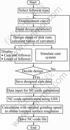
Fig.1 Flowchart of developed CAD/CAM system for CNC grinding machine
3 Optimal grinding speed calculation algorithm
3.1 Cutting height of cutting edge
As a result of studies on surface roughness using grinding theory, it has been thought that the process to calculate a grinding volume should be considered above all using the sectional area of the grinding chips. The volume could be derived from the common equation to have a sectional area of grinding chips [10], but the equation was derived from the hypothesis that the cutting edge of a grinding wheel does not shed or regenerate; thus, this study undertook a modeling for the cutting edge used in actual grinding through the kinematics of machines in general grinding theories. In addition, the surface roughness equations were formulated through their relationships with the subsequent grain, and the equation for the optimal grinding speed was achieved for a constant surface roughness from the correlation between the grinding volume and surface roughness equations.
First, through the kinematics in general grinding theories, it can be considered that grinding is done not only by the cutting edges at the most external angle of the grinding wheel, but also by some cutting edges inside the wheel. In this situation, the center for the rotation of the grinding wheel is O, the location of a random cutting edge is (��, ��) represented as polar coordinates, and then the cutting height of the cutting edge can be calculated.
In this study, the grain modeling for actual grinding is performed using the grinding theory, and the surface roughness equation is defined using the references related to the subsequent grain [8, 10].
Fig.2 shows the condition for the moment where a random cutting edge Y(��, ��) passes through AC. That is, it is assumed that in a short time, point C coincides with the cutting edge B on the outermost surface of the grinding wheel at point E. In Fig.2, v is the rotational velocity of the workpiece. V is the rotational velocity of the grinding wheel. And R is the radius of the grinding wheel. r is the radius of the workpiece. Fig.2 can be formulated as [8]:
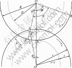
Fig.2 Schematic diagram of flange grinding mechanism
![]()
![]()
![]()
From the above, the cutting height h is calculated as
![]() (1)
(1)
It can be deduced from the above equation that there is a geometric relation between �� and ��, as follows:
![]() (2)
(2)
where �� is the angle velocity of the grinding wheel and �� is that of the workpiece. From Eqs.(1) and (2) above, the cutting height h of the cutting edge is formulated as a function of the coordinates (��, ��) of the cutting edge. However, the depth of notch t is significantly small compared with R, r and ��, so ��2 can be neglected compared with ��1. Under this condition, Eqs.(1) and (2) are re-formulated as follows:
![]() (3)
(3)
 (4)
(4)
Eq.(5) can be drawn from Eqs.(3) and (4) as follows:
![]() (5)
(5)
In Eq.(5), the coefficient of R2��2 is a value to be determined when the radii and velocities of the wheel and workpiece are settled. So, it can be formulated as follows:
![]()
![]() (6)
(6)
where G is a function to be determined by the operating conditions. For the surface grinding, d���� is applied, for the internal grinding, d��-d, and [(1+(v/V)]�� [(1-(v/V)] [9].
Eq.(5) is re-defined through Eq.(6) as follows:
h=R-��+(GR)2��2 (7)
Eq.(7) gives the equation that presents the cutting height of a random cutting edge, Y(��, ��).
3.2 Subsequent grain
As the grinding surface is formed by the tool mentioned in the preceding section, Fig.3 illustrates the finishing process of the finishing surface. The hatching part, as shown in Fig.3, is the profile of the finishing surface; other cutting lines that are not related to the hatching can be considered by realizing that the cutting of each location precedes the final grinding and, consequently, are not related to the final grinding.
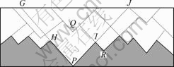
Fig.3 Forming process of surface
GHPIJ, as shown in Fig.3, is an example of a two-cut groove (however, lines GH and IJ are virtual cutting lines). The summit P of the groove becomes the name of GHPIJ, and the external line is a cutting edge that passes through it. Considering the two cutting grooves Q and R, Q is included in P, yet R is not. The cutting edge P that generates the cutting groove P is defined as a subsequent grain for the cutting edge Q. Cutting edges P and Q can have coordinates of (��, ��) and (��0, ��0), respectively. As shown in Fig.4, the cutting heights of the two grooves formed by the two cutting edges are presented as (��, ��) and (��0, ��0), respectively, as their coordinates in the grinding wheel. When h and h0 are indicated as the cutting heights of the two grooves produced by the two cutting edges, the following equation can be drawn from Eq.(7) [8]:
![]() (8)
(8)
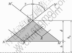
Fig.4 Schematic diagram of relationship of subsequent grain
As shown in Fig.4, the cutting lines of Q, QM�� and QN��, are extended, the intersection points with the line of the cutting height h are M and N, and then ��QMN has no cutting groove except P. If it is assumed that there is a cutting groove such as R as shown in Fig.3, groove R includes groove Q. The gap of the cutting heights of R and Q is less than that of Q and P, so Q is the subsequent grain for P and Q, and this is in opposition to the definition of a subsequent grain that has been mentioned previously.
Subsequently, it is found that only one cutting edge is in the volume of the grinding wheel: the area ��QMN.
Fig.5 shows the grinding volume according to the cutting edge Q and the subsequent grain P. The lines of Q��Q�� and P��P�� are the cutting heights of h0 and h, respectively. Besides, the volume u in the grinding wheel that corresponds to ��QMN of the workpiece has a band with sides of Q��Q�� and P��P��, and it can be considered to be the volume of a trigonal prism. This volume is formulated as follows:
![]() dh=
dh=![]() (9)
(9)
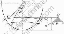
Fig.5 Schematic diagram of grinding volume according to subsequent grain
The following equation can be defined because the number of cutting edges in the unit volume of the wheel is 1/��3:
![]() (10)
(10)
The grinding surface is finished by several cutting edges with a cutting height close to 0. Only cutting grooves from the cutting edges with no subsequent grains in grinding surfaces remain based on the fact that factors with subsequent grains disappear completely, as stated above.
Thus, when the two groove heights that exist in the grinding surface are ![]() and
and ![]() the left side of Eq.(10) can be set to less than 1:
the left side of Eq.(10) can be set to less than 1:
![]() (11)
(11)
When ![]()
![]()
![]() are the heights of two grooves, a triangle with a contact point of
are the heights of two grooves, a triangle with a contact point of ![]() a height of
a height of ![]() and a settled angle of 2�� has no cutting grooves, as presented in Fig.6.
and a settled angle of 2�� has no cutting grooves, as presented in Fig.6. ![]() and
and ![]() are carved for two grooves and the following Eq.(12) can be formulated by determining the highest point
are carved for two grooves and the following Eq.(12) can be formulated by determining the highest point ![]() and the lowest point
and the lowest point ![]()

Fig.6 Interaction of random groove between ![]() and
and ![]() on shape of grinding surface
on shape of grinding surface
![]() (12)
(12)
![]() (13)
(13)
where G is defined as G=v/V[(1/D)��(1/d)]-1 drawn from Eq.(6), and the above equation is re-defined as follows:
 (14)
(14)
where V is the velocity of the grinding wheel (m/s); D is the diameter of the grinding wheel (mm); �� is the end cutting edge angle of the grain (��); v is the number of grains; d is the diameter of the workpiece (mm).
The cutting height of the grain (Hv) changes into the surface roughness and the center line-average-height is used in this work. Also, Hcp is 0.256Hv [7] in accordance with the correlation between Hcp and Hv. Therefore, Eq.(14) can be rewritten as
 (15)
(15)
From Eq.(15), the optimal grinding speed to obtain a constant surface roughness is proposed as
 (16)
(16)
4 CAM manufacturing experiments and results
4.1 NC code generated by developed CAM system
The dialog box created for the cam machining is shown in Fig.7. There is a source selection radio button on the top of the dialog box. It can be selected ��From Design Data�� as shown in Fig.7 to generate NC code for the Palanquin cam button.
The check box under the radio button is unchecked because the experiment is limited to external grinding. Each condition and parameter of the grinding wheel
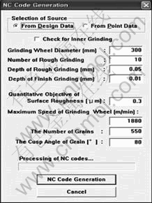
Fig.7 NC code generation
speed, rough grinding number, rough grinding depth, finished grinding depth, quantitative objective of surface roughness, optimal speed of grinding wheel, grain number, and grain cusp angle are input below the check box. Then, the optimal grinding speed algorithm with a constant roughness applied NC code can be obtained through the CAM system. Experiments were performed using the developed high precision cam profile in a CNC grinding machine for three types of cams, as shown in Fig.8. As the cam is made from steel (SS41), a CBN grinding wheel was used in the experiments. The number of grains in Eq.(16) is 550 and the end cutting edge angle of grain is 80��. As a result, the optimal grinding speed can be obtained to maintain a constant surface roughness. The NC code was obtained using the developed CAD/CAM system [20].
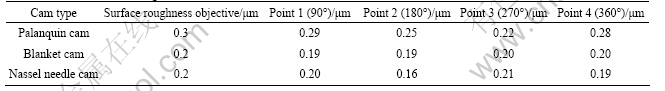
As a result of the experiments (Table 1), the reduction ratio of the machining time is 27.1%, leading to the higher productivity. In order to confirm that the objective of the surface roughness is achieved, the surface roughness (Ra) of the cams was measured using a Mitutoyo Surftest SV-624. The measuring points were selected four times via a 90�� rotation. Table 2 gives the results of the surface roughness.
As given in Table 2, the objective of the constant surface roughness was achieved using the proposed algorithm.
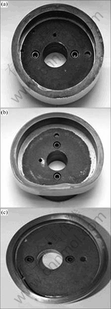
Fig.8 Results of grinding machining: (a) Palanquin cam; (b) Blanket cam; (c) Nassel needle cam
4.2 Development of cam profile measuring device
The measuring precision of the final cam profile after grinding is essential. Cam measuring is usually performed using either a hand-operated method or CMM. Reading the needle on the dial gauge by dividing the CAM using angle indexing is normal for hand-operated methods. CMM is sometimes used, but it requires trained
Table 1 Variables affecting machinabillity
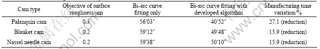
Table 2 Results of surface roughness (Ra)
workers, the measuring instruments are expensive, and it takes a very long time because it uses a general purpose machine. Therefore, the cam profile measuring and automated analysis were performed using the cam profile measuring device developed in this study. The developed device is composed of a servo motor, a CNC controller, a rotary encoder, and a laser-CCD interferometer. Also, this device is a non-contact measurement system using a laser-CCD interferometer. Fig.9 shows the overall flow chart of data acquisition for a cam profile measuring device.
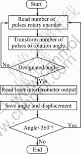
Fig.9 Flow chart of data acquisition for cam profile measuring device
5 Measured results
The three abovementioned cams (Palanquin cam, Blanket cam, and Nassel needle cam) were measured using the cam profile measuring device. Fig.10 shows the results of the Blanket cam measurements. To discern the repetition precision, the measurements were performed five times each. The maximum size of the repetition error was ��1.5 ��m. As Fig.10 shows, the maximum manufacturing error was 8.4 ��m, and the location where the maximum error was caused was 50�� from the measured result report.
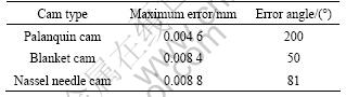
The other two cams were measured, and the results are given in Table 3. Therefore, it can be concluded that the developed measuring device is sufficiently useful.
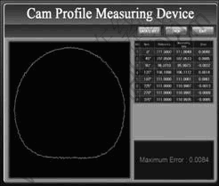
Fig.10 Display of measured data from blanket cam
Table 3 Results of measurements (Ra)
6 Conclusions
A CAD/CAM system and profile measuring device for a CNC grinding machine to obtain an optimal grinding speed with a constant surface roughness was established from general grinding theory. Three types of disk cam (Palanquin cam, Blanket cam, and Nassel needle cam) were successfully manufactured by the developed CAD/CAM system with a reduced machining time. It is also shown that the developed CAD/CAM system and profile measuring device can be effectively applied to the manufacture of high-precision cams.
Acknowledgement
This work is supported by grant No. RTI04-01-03 from Regional Technology Innovation Program of the Ministry of Knowledge Economy (MKE) of Korea and the Program for the Training of Graduate Students on Regional Innovation which was conducted by the Ministry of Commerce Industry and Energy of the Korean Government.
References
[1] KIM H S, JEONG K S, LEE G D. Structural design and evaluation of the three axis ultra-precision CNC grinding machine [J]. Trans of KSME, 1995, 19(12): 3392-3402.
[2] GAO Y, WEBSTER A J. Computer simulation of the deformation of slender, multi-diameter rollers during grinding [J]. International Journal of Machine Tools and Manufacture, 1991, 31: 88-93.
[3] SHIN J H, KANG D W, KIM J S, KIM D W. A study on shape design approach of disk cams using relative velocity of followers [J]. Journal of Korea Society Precision Engineering, 2000, 17(2): 185-192. (in Korean)
[4] KANG D W. A study on design automation technology of complex mechanisms with disk cams and cylindrical cams for multi-axis motion control [D]. Changwon National University, Korea, 2000. (in Korean)
[5] BOLTON K M. Biarc curves [J]. Computer-Aided Design, 1975, 7(2): 89-92.
[6] LIM S H, LEE C M. A study on the development of CAD/CAM system for high precision cam profile CNC grinding machine [J]. Transactions of the Korean Society of Machine Tool Engineers, 2006, 15(5): 44-50. (in Korean)
[7] LEE J D. Theory of three dimensional measurement [M]. Sungandang, Korea, 2001: 251-258. (in Korean)
[8] PARK C W. Theory of grinding machining [M]. Science Technology, Korea, 2000. (in Korean)
[9] CHO S R. A study on the modeling and manufacturing of roller gear cam for CNC machine center [D]. Changwon National University, 2001. (in Korean)
[10] KIM D W. Method of workshop practice [M]. Chungmoongak, Korea, 2005. (in Korean)
[11] SHIGLEY J E, UICKER J J. Theory of machines and mechanisms [M]. McGraw-Hill, 1980: 226-241.
[12] MARTIN G H. Kinematics and dynamics of machines [M]. McGraw-Hill, 2002: 353-369.
[13] NORTON R L. Design of machinery [M]. McGraw-Hill, 2004: 353-369.
[14] ERDMAN A G, SANDOR G N. Mechanism designing: analysis and synthesis [R]. Korea: Prentice-Hall International, Inc, 1991.
[15] WILSON C E, SALDER G N. Kinematics and dynamics of machinery [M]. HarperCollins College Publishers, 1993: 52-84.
[16] NORTON R L. CAM design and manufacturing handbook [M]. Industrial Press Inc, 2009.
[17] GA T Z, SHPITALNI M, MALKIN S. Design and manufacturing analyses for integrated CAD/CAM of cams [J]. ASME Journal of Engineering for Industry, 1989, 111: 307-314.
[18] TSAY D M, WEI H M. A general approach to the determination of planar and spatial cam profiles [J]. ASME Journal of Mechanical Design, 1996, 118: 259-265.
[19] SHIN J H, LEE C M, KIM J S. Shape design of disk cam mechanisms using instant velocity center [C]// Proceedings of 6th International Symposium on Transport Phenomena and Dynamics of Rotating Machinery. 1996: 178-186.
[20] LIM S H. A study on the development of a high precision cam profile grinding machine and operating CAD/CAM system [D]. Changwon National University, Korea, 2007. (in Korean)
Foundation item: Project(RTI04-01-03) supported by the Regional Technology Innovation Program of Ministry of Knowledge Economy (MKE), Korea
Received date: 2010-03-28; Accepted date: 2010-11-30
Corresponding author: LEE Choon-Man, PhD, Professor; Tel: +82-55-213-3622; E-mail: cmlee@changwon.ac.kr
[5] BOLTON K M. Biarc curves [J]. Computer-Aided Design, 1975, 7(2): 89-92.
[8] PARK C W. Theory of grinding machining [M]. Science Technology, Korea, 2000. (in Korean)
[10] KIM D W. Method of workshop practice [M]. Chungmoongak, Korea, 2005. (in Korean)
[11] SHIGLEY J E, UICKER J J. Theory of machines and mechanisms [M]. McGraw-Hill, 1980: 226-241.
[12] MARTIN G H. Kinematics and dynamics of machines [M]. McGraw-Hill, 2002: 353-369.
[13] NORTON R L. Design of machinery [M]. McGraw-Hill, 2004: 353-369.
[16] NORTON R L. CAM design and manufacturing handbook [M]. Industrial Press Inc, 2009.
