

J. Cent. South Univ. (2020) 27: 3040-3052
DOI: https://doi.org/10.1007/s11771-020-4527-3

Stability analysis of underground surrounding rock mass based on block theory
LIN Jian-yun(�ֽ���)1, 2, ZUO Yu-jun(�����)1, 2, WANG Jian(����)3, ZHENG Lu-jing(֣»�Z)1, 2,
CHEN Bin(�±�)1, SUN Wen-ji-bin(���ļ���)1, 4, LIU Hao(����)1, 2
1. Mining College, Guizhou University, Guiyang 550025, China;
2. School of Resource and Environmental Engineering, Guizhou University, Guiyang 550025, China;
3. School of Resources and Safety Engineering, Central South University, Changsha 410083, China;
4. Priority Research Centre for Geotechnical Science and Engineering, The University of Newcastle,Callaghan, NSW, 2308, Australia
 Central South University Press and Springer-Verlag GmbH Germany, part of Springer Nature 2020
Abstract:
Evaluation of the performance of existing support in underground tunnels is of great importance for production and interests. Based on field investigation, the shape and number of joints and fractures were investigated in the mining area. Then, the stability of each structural blocks is analyzed by 3D wedge stability analysis software (Unwedge). Moreover, a new analysis method based on critical block theory is applied to analyze the stability of excavated laneways in continuous and discontinuous rock and monitor the stress changes in a fractured tunnel rock mass. The test results indicate that the 3D wedge stability analysis software for underground excavation can evaluate deep tunnel support. Besides, there is no direct relation between the size of the block and the instability of the tunnel. The support method, on large and thick key blocks, needs to be improved. In a broken tunnel section, U-shaped steel support can effectively promote the stress state of the surrounding rock. By monitoring the surrounding rock, it is proven that the vibrating string anchor stress monitoring system is an efficient and real-time method for tunnel stability evaluation.
Key words:
key block theory; Unwedge analysis software; stress monitoring system; support evaluation��
Cite this article as:
LIN Jian-yun, ZUO Yu-jun, WANG Jian, ZHENG Lu-jing, CHEN Bin, SUN Wen-ji-bin, LIU Hao. Stability analysis of underground surrounding rock mass based on block theory [J]. Journal of Central South University, 2020, 27(10): 3040-3052.
DOI:https://dx.doi.org/https://doi.org/10.1007/s11771-020-4527-31 Introduction
Around the world, the instability of laneways causes heavy casualties and serious economic losses each year [1-7]. To reduce or prevent instability, it is necessary to analyze the tunnel stability and gain a clear understanding and evaluation of rock mass failure mechanisms. In recent years, ZUO et al [8], LI et al [9-12], ZHU et al [13, 14], and other experts have done many scientific studies to assess the harm caused by dynamic disturbance in deep mining.
Due to the variable nature of rock masses, it is difficult to determine the tunnel stability. These rock masses mainly include faults, joints, anisotropy, bedding, discontinuities, etc. In geotechnical engineering and underground mining, the tunnel stability needs to be evaluated to ensure a stable state during construction and operation. Generally,field exploration of tunnel stability at different stages has different details due to the weak structural planes and the massive structure formed by hard discontinuous surface cutting. Analysis of such structures is of great importance to identify dangerous areas [15-20].
Block theory is always applied in the stability analysis in rock mass engineering. The publication of GOODMAN [21] indicates that block theory has been used as an effective method for rock mass engineering analysis. Since then, block theory has been widely applied in various projects due to its distinct characteristics. KOCHARYAN et al [22- 25] proposed a method for constructing three- dimensional block structures based on jointed rock mass parameters, and the stability of the block and its influence on the tunnel were studied. Based on block theory, WANG et al [26] developed geotechnical structure and model analysis software (GeoSMA-3D) and applied it to analyze a rock slope. GREIF et al [27] carried out static analysis of 45 selected Medieval Castle Rock Slopes in Slovakia and calculated the safety factors of more than 12000 potentially unstable blocks under static conditions using key block theory. DONG et al [28] analyzed the stability of the Jiaojia rock mass and established a nonprobabilistic reliability model of the surrounding rocks in underground caverns which can be used in the absence of field data. KRASNOVSKY et al [29] proposed a method for identifying the weakening position of rock blocks and applied it to rock pillars. HATZOR et al [30] collected the block failure data of Berkeley��s two tunnel sidewalls and proposed a method of integrating block motion criteria in an empirical rock classification system. CHEN [31] used the First-order Second-moment Method (FOSM) to assess the probability of key block formation and the possibility of key block failure. GONG et al [32-35] carried out the simulation experiments using a rock true-triaxial electrohydraulic servo mutagenesis testing system, and a wireless microcamera was used to record and monitor the damage process on the sidewalls of the tunnel in real time. WANG et al [35] combined supporting technology with U-shaped steel support and proposed the anchor-grouting approach for the surrounding soft rock. The numerical simulation of the combined supporting technology and in-situ deformation monitoring results show that the soft rock surrounding the roadway has been supported effectively.
In addition, support evaluation is important for the roadway stability. Therefore, it is of great significance to develop reliable monitoring technology and predict potential roadway instability based on test results. URBANCIC et al [36] outlined the current status of seismic monitoring instruments in underground mines in Canada and identified the changes in the direction of principal stress during deep mining through seismic monitoring. DONG et al [37-40] used micro seismic monitoring technology to investigate the fracture location and stress condition characterization for the physical process of rock mass deformation and failure, which provided guidance for the evaluation of dangerous areas.
With the increase of mining depth, the tunnel stress increases correspondingly, which increases the risk of surrounding rock breaking tunnel instability, as shown in Figure 1. The main destruction forms include falling roofs caused by broken surrounding rock and collapse caused by joint fracture development (Figure 1). To understand the deep rock mass characteristics in the Jiaojia Gold Mine, a vibrating wire anchor stress monitoring system is set up, and stress monitoring tests are carried out on the working face of the fractured rock mass. In addition, the evaluation of deep tunnel support in mining areas, combined with the numerical simulation, is carried out. The proposed research method can provide useful guidance for roadway support under deep complex geological conditions, and ensure the production of mine economic benefits and safety.
2 Investigation of joints and fractures in study area
The Jiaojia gold deposit is in a tectonic fracture zone, the orebody and surrounding rock are all broken and unstable. According to rock mechanics, the rocks of the Jiaojia gold deposit are semi-hard/hard rock, with tensile strength only 1/9- 1/19 of the uniaxial compressive strength. Moreover, the tensile strength perpendicular to the surface of the structure tends to be zero. The maximum principal tectonic stress field in the mining area is horizontal with azimuth SE-NW, which is approximately perpendicular to the direction of the orebody.
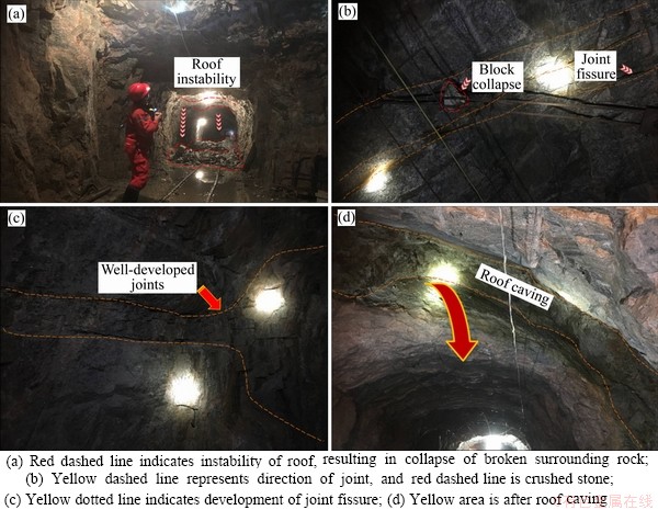
Figure 1 Main factors of tunnel instability in Jiaojia Gold Mine:
The fractured rock mass is easily affected by blasting vibration. When the structural plane slip exceeds its displacement limit, the rock mass structure collapses, with obvious deformation. In the working progress of well and tunnel engineering, when the tensile stress of the roof exceeds the tensile strength of the rock mass, the roof collapses easily. This is the main manifestation of ground pressure activity in the Jiaojia Gold Mine. Therefore, the investigations of joint fissures are of great significance to understand the surrounding rock block structure.
A joint fracture is a structural plane formed in rock masses under stress. It is a structural fracture, with no or little displacement. Although the size of these joint fractures are not notable, their numbers are remarkable. The stability and destruction modes and degrees of orebodies and their surrounding rocks are controlled by different positions, quantities, sizes, and shapes of joints [41-43]. Joint fissures are mostly associated with structural stress, and the tectonic stress field and movement mode can be deduced from the joint fissures, which provides the basic data for the mechanical analysis of the regional tectonic stress field and structural system. It can be seen that the investigation and statistical analysis of joints and fractures are very valuable in geological engineering surveying. To fully reflect the stability of the deep rock mass in the Jiaojia Gold Mine, the survey line method was applied to investigate the joints and fractures in the mining area.
In the middle of the -470 m mining area, 13# joints were selected to investigate the joints and fractures, and 65 joints were measured. The cluster analysis of joint fissures and the statistical analysis of the data are shown in Figure 2. The structural plane was discrete and the dominant position was roughly divided into 4 groups according to their tendency: The first group tended to be 0��-20��, with an average tendency of 12.9��, and mean obliquity of 75.5��. The second group tended to be 290��-310��, with an average tendency of 300.4��, and mean obliquity of 78.5��. The third group tended to be 110��-130��, with an average tendency of 112.6��, and mean obliquity of 60.5��. The fourth group tended to be 200��-230��, with an average tendency of 213.3��, and mean obliquity of 70.1��. According to the trend, the dominant position can be divided into 3 groups (Figure 2), 30��, 280�� and 300��, and the inclination is mostly distributed at 30��-90��.
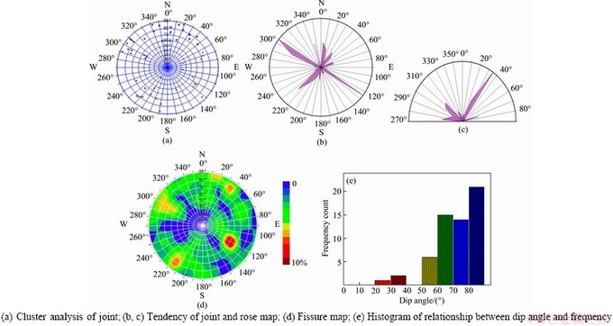
Figure 2 Investigation results of 13# pulse joint fracture in the middle part of -470 m:
3 Key block stability analysis
Longitudinal and transverse cutting of joints and structural planes make rock mass properties quite different from those of intact rock. The key block theory has been widely applied in the engineering field as an important method for analyzing jointed rock mass reliability [44]. To study the failure mechanism and stability of jointed rock masses in mining areas, the key block theory, combined with Unwedge software, is applied in this paper. Stability analysis was carried out on the results of the investigation of 13# joints in the middle section of the -470 m mining area, and the appropriate parameters were determined and selected in the Unwedge software for support analysis and evaluation.
In Unwedge, 3 groups of structural planes are analyzed each time, and the generated blocks are numbered automatically. Generally, the blocks formed by cutting structural planes mainly exist on the top and sides of the tunnel. As the mining work face deepens, the ground stress in the rock surrounding the roadway and mining site keeps increasing. Roof and side fall easily cause rock burst accidents. Therefore, for the development of the structure surface, emphasis should be placed on the stability of blocks formed by cutting structural planes. The following is a simulation of the 13 joints in the middle section of the -470 m mining area.
3.1 Stability analysis of a block formed by 1, 2 and 3 combined structural planes
From blocks formed in a combination of the 1, 2, and 3 structures, blocks 4 and 8 are at the top, blocks 3 and 6 are on the sides, and 5 is stable at the bottom of the tunnel as shown in Figure 3. The safety factor of each block is shown in Table 1. According to the results, the safety factors of blocks 3, 4 and 5 are larger than the critical value of 1 in the stable block formed by the combination of structural planes 1, 2 and 3. The safety coefficients of blocks 6 and 8 are all below the critical value of 1, which indicates an unstable condition.
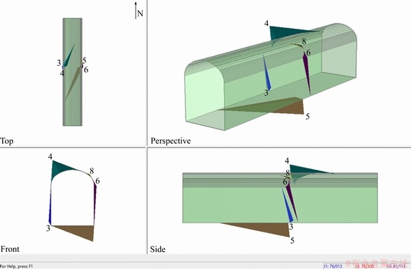
Figure 3 Spatial distribution of blocks formed by combined cutting of 1, 2 and 3 structural planes
Table 1 Safety factor of blocks formed by 1, 2 and 3 cuts of structural planes

Accordingly, blocks 6 and 8 should be supported to ensure safety in production.
The normal and shear stress of each structural plane on the block can be obtained by software analysis and calculation, as shown in Figure 4. The maximum normal stress on each structural plane formed by the 1, 2 and 3 cuts is 2.65 MPa and the minimum is 0.16 MPa. The maximum shear stress is 1.30 MPa, and the minimum is 0.11 MPa. After determining the location of the normal stress and the maximum shear stress, attention should be paid to the stability of the site to avoid stress concentration and rock mass instability.
Since the exposed areas of blocks 6 and 8 are small, pipe bolts are installed at two locations for support. According to an actual mine condition, a 1.8 m pipe seam bolt was selected. By adjusting the row spacing between the anchor bolts and calculating the safety factor, the bolt and row spacing are set at 1.3 m. Safety factors are in Table 1. After bolting, all the block safety factors are greater than the critical value of 1, which indicates that the rock mass is in a stable state.
3.2 Stability analysis of blocks formed by 1, 3 and 4 combined structural planes
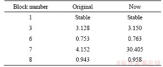
In the blocks formed by the 1, 3 and 4 structural planes, blocks 3 and 6 are at two sides of the tunnel, and block 1 is at the bottom. The distribution of each block is shown in Figure 5. The safety factor of each block is shown in Table 2. According to the results, in the blocks formed by the 1, 3 and 4 structural planes, the safety factors of blocks 1, 3 and 7 are all larger than the critical value of 1, indicating that they are stable blocks. The safety factors of blocks 6 and 8 are less than 1 and are unstable. Therefore, blocks 6 and 8 should be supported to ensure safety in production.
The normal and shear stress of each structural plane on the block can be calculated, as shown in Figure 6. The maximum normal stress on each structural plane of the blocks formed by the 1, 3 and 4 cuts is 2.42 MPa, and the minimum is 0.25 MPa. The maximum and minimum shear stresses are 1.41 and 0.14 MPa, respectively.
The length of the pipe joint anchor is chosen as 1.8 m for support because of the large volume and mass of blocks 6 and 8 in the 1, 3 and 4 combinations of structural planes. In the process of adjusting the spacing, the safety factors of blocks 6 and 8 vary slightly. Even if row and column spacing are set to 0.8 m, the safety factor is still less than the critical value of 1. The effect of the pipe support is shown in Figure 7. The safety factor for each block at the spacing of 0.8 m is shown in Table 2. It is believed that even if the spacing between the rows is very small, the safety factor will never reach the critical value of 1, according to its change in the adjustment process. Furthermore, as the anchor spacing shortens, the support cost increases sharply and the economic benefits decrease. In this case, to meet the product safety requirements, U-shaped steel is recommended for support.
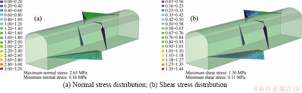
Figure 4 Distribution of normal stress and shear stress on structural plane of blocks formed by 1, 2 and 3 cuts of structural planes:
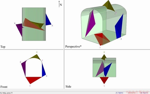
Figure 5 Spatial distribution of blocks formed by combined cutting of 1, 3 and 4 structural planes
Table 2 Safety factor of blocks formed by 1, 3 and 4 cuts of structural planes
3.3 Stability analysis of blocks formed by 2, 3 and 4 combined structural planes
Structure surfaces 2, 3, and 4 were cut into 4 blocks, block 1 is stable at the bottom of the tunnel, blocks 3 and 6 are at the sides, and block 8 is at the top of the tunnel. The spatial distribution of each block is shown in Figure 8. The block safety factor is calculated and provided in Table 3. It can be seen that #1 is stable, and the safety factors of blocks 3 and 6 are greater than 2, so they are safe in the production process. The safety factor of block 8 is only 0.826, less than the design safety factor, so the stability of #8 needs to be further analyzed.
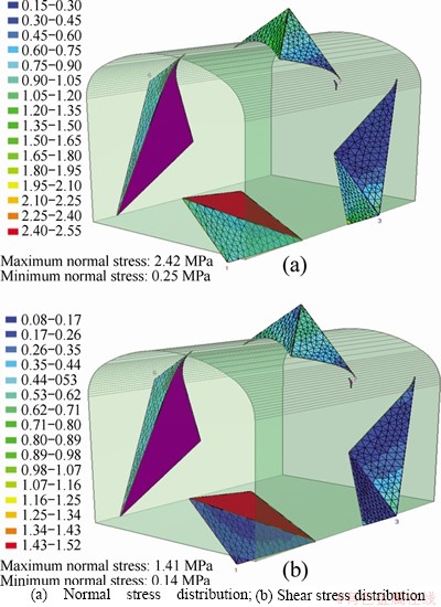
Figure 6 Distribution of normal stress and shear stres s on structural plane of blocks formed by 1, 3 and 4 cuts of structural planes:
The normal and shear stress on the structural plane can be calculated, as shown in Figure 9. The normal and shear stress at different parts of the structural plane is different. The minimum and maximum values of normal stress are 0.02134 MPa and 4.767 MPa, respectively, and the minimum and maximum values of shear stress are 0.040408 MPa and 2.20982 MPa, respectively.
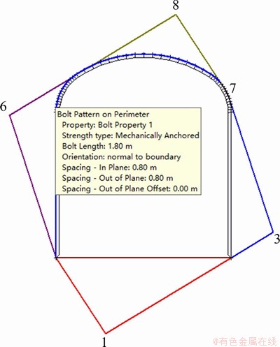
Figure 7 Impression drawing after installing anchor bolt support
The volume of #8 is 17.192 m3. The weight is 464.185 kN. A bolt is used for support, and the safety factor is analyzed and calculated. According to the field condition of the Jiaojia Gold Mine, a 1.8 m pipe joint anchor is used for support, by adjusting the anchor and row spacing between the bolts. A 2 m anchor spacing and 1.9 m row spacing are finally determined. The safety factor of #8 reaches 2.01, which fits with the requirements of safety production. The safety factor for each block is shown in Table 3. The specific support condition is shown in Figure 10. It can be seen that the use of 5 slotted pipe bolts can meet the requirements. Thus, in the middle 13# joint of the -470 m mining area, bolt supports can meet the requirements for roadway stability.
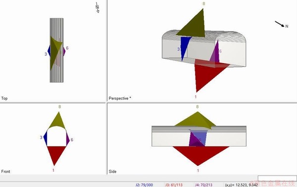
Figure 8 Three views of a block formed by a structural plane cutting
Table 3 Safety factor of blocks formed by 2, 3 and 4 cuts of structural planes
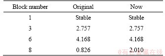
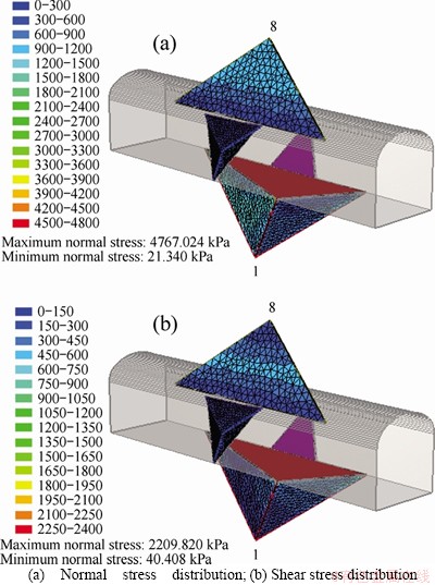
Figure 9 Distribution of normal stress and shear stress on structural plane of blocks formed by 2, 3 and 4 cuts of structural planes:
4 Stability analysis of surrounding rock in-field monitoring
A broken tunnel in the middle slope of the -630 m mining area is selected to conduct stress monitoring tests. The main rocks of the Jiaojia Gold Mine deposit are porphyritic biotite granite and yellow iron sericite granite. The upper and lower footwall of the orebody is sericite, and the indirect surrounding rocks are black cloud hornblende, orthoclase diorite, black cloud plagioclase gneiss and black cloud granulite. The footwall is relatively intact, and the upper part is broken. The main body of the ore is beresite. Since the position of the vibrating wire anchor stress sensor is very close to the blasting face, the effect of blasting on the tunnel is obvious, and it can be analyzed by monitoring the data.
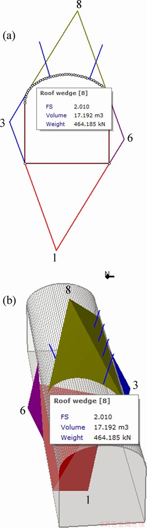
Figure 10 Result of supporting block 8 with slotted bolts
The ramp consists of 4 vibrating wire anchor stress gauges, a data acquisition system and an analytical computer. A 64-channel vibrating wire anchor stress monitoring system is set up. Each vibrating wire anchor stress gauge has 4 vibrating wire stress sensors and 1 temperature sensor equally distributed in 4 parts. The plane diagram of the test ramp is shown in Figure 11. The green and red circles represent the hole and bottom of the Z-axis of the vibrating wire anchor. Vibrating wire anchor stress gauges I, III and IV are installed in a U-shaped steel section that supports the broken surrounding rock. Gauge II is installed in a no support section. The coordinates and installation angle of stress meters I to IV are shown in Table 4.
The stress meter is connected to a readout in the 1000-3600 Hz reading range and set to the stress mode, to start data measuring. The output of the vibrating string stress meter is micro strain. The unit directly displayed by the readout instrument is 0.39102��10-3 f 2. The difference between the initial reading and the current reading can be calculated by subtracting the initial reading from the current reading. Anchor rod stretching will increase (Rt-R0=+). Conversely, anchor rod stretching will decrease (Rt-R0=-).
After installation and debugging, a set of initial data is collected. To avoid excessive data collection, data cannot be exported. Data copy work is carried out every 3-5 d, the data collected earlier in the acquisition instrument is cleared and the collection work continues. After the data acquisition is completed, the axial force variation trend is calculated and analyzed, as shown in Figure 12. A positive value indicates that the bolt stress gauge axial force is tensile, and a negative value indicates that it is compressive.
The installation position of stress meter I is close to laneways. According to the monitoring results, the axial force of the S1 to the S4 sensor is tensile, which may indicate that the steel support loses contact with the surrounding rock and fails to achieve its function. Then, the axial force gradually stabilizes, and the steel support begins to take effect. Stress gauge III is installed in the middle of the tunnel, where the steel support closely contacts the tunnel roof. Therefore, the axial forces of the S9 to the S12 sensors are all compressive. Stress gauge IV is installed near the other side of the roadway. The axial forces of the S13 and the S14 sensors are tensile. The axial force of the S15 and the S16 sensors is compressive, which shows that the steel support is in close contact with the surrounding rock. From the diagram, before and after the explosion, the data of all sensors show an abrupt change. With the increase of mining depth, the influence of blasting on the test section gradually weakens, and the curve is more smooth. Based on the overall axial force, the variation of stress meter II shows nonlinear growth, while the other 3 stress meters tend to be balanced, also the surrounding rock loosening ring is less than 2 m , which shows that the steel support has made a significant improvement in the rock deformation control after excavation. It is worth nothing that, the S7 sensor cannot receive signals due to poor contact.
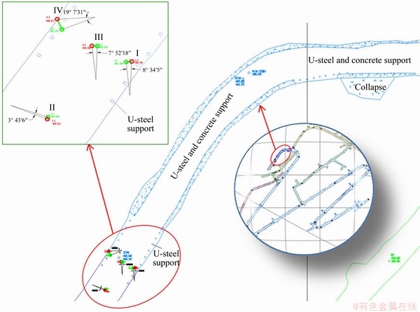
Figure 11 Plane map of slanted ramp in Jiaojia Gold Mine
Table 4 Azimuth and setting angle of vibrating wire bolt stress sensor
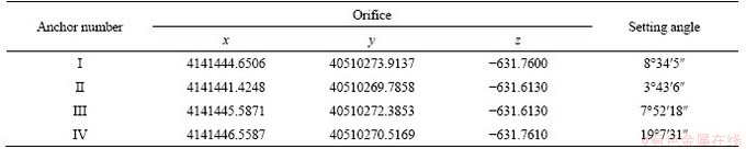
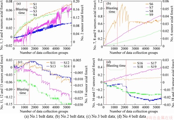
Figure 12 Real time monitoring of vibrating wire bolt stress meter (The red dotted line represents the blasting time group):
The temperature sensor data extracted from the stress gauges are plotted in Figure 13. The temperature trends of the T1, T3 and T4 sensors are the same and remain at a certain range. The increasing trend temperature anomaly of the T2 sensor is large and related to the installation position of stress meter II. After blasting, there is a sudden change in temperature.
According to Figures 12 and 13, bolts I, III and IV are in the support section, and their axial force values first increase and then gradually stabilizes, while the temperature values change slowly and steadily. No. II bolt is in the unsupported section, and its axial force has a large fluctuation range and a straight upward trend, and its temperature shows a dramatic wave dynamic, this proves that the U-shaped steel support improves the stability of the roadway in this section.
Figure 13 Temperature sensor data extracted from stress gauges (The curves of orange, black, red and green indicate the change of temperature of stress gauge I, II, III and IV with time. The blue dotted line represents the blasting time group)
As previously described, through the real-time vibrating wire anchor stress monitoring system, stress redistribution will occur in the form of tensile or compressive stress in the surrounding rock after excavation. With the application of the U-shaped steel support, the surrounding rock stress tends to be stable, whereas the stress increases without the U-shaped steel support. Since the rock surrounding the tunnel is relatively broken, without proper support after excavation, the change and redistribution of surrounding rock stress will easily cause roof collapse and wall caving accidents. The adoption of U-shaped steel supports for broken surrounding rock proves to be effective.
5 Conclusions
The evaluation of the existing support is important for mine safety, production, and benefits. In response to this critical issue, through field layout and measurement, the joints and cracks in the mining area are investigated, and the surrounding rock characteristics of the 13# joints in the middle of the -470 m mining area are obtained. A new analysis method based on key block theory is applied to analyze the surrounding rock. As the data show, bolt support can meet the stability requirements of crossing tunnels. For large and thick key blocks, steel support can be selected, but it will cause difficulties in support and increase cost. Considering the stress state and support of the rock mass, the vibrating string stress monitoring system is applied. When blasting occurs, the U-shaped steel support could improve the stability of the surrounding rock mass. However, without the U-shaped steel support, stress in the surrounding rock increases continuously. If the support is not carried out in time, the change and redistribution of surrounding rock stress will cause accidents such as roof fall and spalling. Through data analysis and practical application, it is proven that the vibrating string stress monitoring system is an efficient and real-time method for tunnel stability evaluation. This study could provide some reference value for the safety evaluation of deep tunnels.
Contributions
LIN Jian-yun, ZUO Yu-jun and WANG Jian analyzed the calculation results and wrote the article; ZHENG Lu-jing collected the construction site information; WANG Jian and CHEN Bin carried out the numerical simulation; SUN Wen-ji-bin and LIU Hao processed the data; and ZUO Yu-jun offered useful suggestions for the preparation and writing of the paper. All authors replied to reviewers�� comments and revised the final version.
Conflicts of interest
LIN Jian-yun, ZUO Yu-jun, WANG Jian, ZHENG Lu-jing, CHEN Bin, SUN Wen-ji-bin and LIU Hao declare that they have no conflict of interest.
References
[1] MENG Xiang-rui, PENG Rui, ZHAO Guang-ming, LI Ying-ming. Roadway engineering mechanical properties and roadway structural instability mechanisms in deep wells [J]. KSCE Journal of Civil Engineering, 2018, 22(5): 1954-1966. DOI: 10.1007/s12205-017-1298-y.
[2] JIANG Li-shuai, MITR H S, MA Nian-jie, ZHAO Xi-dong. Effect of foundation rigidity on stratified roadway roof stability in underground coal mines [J]. Arabian Journal of Geosciences, 2016, 9(1): 32-44. DOI: 10.1007/s12517- 015-2033-y.
[3] PENG Rui, MENG Xiang-rui, ZHAO Guang-ming, LI Ying-ming, ZHU Jian-ming. Experimental research on the structural instability mechanism and the effect of multi-echelon support of deep roadways in a kilometer-deep well [J]. Plos One, 2018, 13(2): 1-24. DOI: 10.1371/journal. pone.0192470.
[4] WANG Q, PAN R, JIANG B, LI S C, HE M C, SUN H B, WANG L, QIN Q, YU H C, LUAN Y C. Study on failure mechanism of roadway with soft rock in deep coal mine and confined concrete support system [J]. Engineering Failure Analysis, 2017, 81: 155-177. DOI: 10.1016/j.engfailanal. 2017.08.003.
[5] MENG Qing-bin, HAN Li-jun, XIAO Yu, LI Hao, WEN Sheng-yong, ZHANG Jian. Numerical simulation study of the failure evolution process and failure mode of surrounding rock in deep soft rock roadways [J]. International Journal of Mining Science and Technology, 2016, 26(2): 209-221. DOI: http://dx.doi.org/10.1016/j.ijmst.2015.12.006.
[6] KANG H P, LIN J, FAN M J. Investigation on support pattern of a coal mine roadway within soft rocks-a case study [J]. International Journal of Coal Geology, 2015, 140: 31-40. DOI: 10.1016/j.coal.2015.01.003.
[7] XUE Yi, GAO Feng, LIU Xing-guang, LIANG Xin. Permeability and pressure distribution characteristics of the roadway surrounding rock in the damaged zone of an excavation [J]. International Journal of Mining Science and Technology, 2017, 27(2): 211-219. DOI: 10.1016/j.ijmst. 2017.01.003.
[8] ZUO Y J, WANG J, DONG L J, SHU W W, YU M L, SUN W J B, WU Z H. Optimization for U-shaped steel support in deep tunnels under coupled static-dynamic loading [J]. Advances in Civil Engineering, 2019, Article 4172103. DOI: 10.1155/2019/4172103.
[9] LI X B, GONG F Q, WANG S F, LI D Y, TAO M, ZHOU J, HUNG L Q, MA C D, DU K, FENG F. Coupled static-dynamic loading mechanical mechanism and dynamic criterion of rockburst in deep hard rock mines [J]. Chinese Journal of Rock Mechanics and Engineering, 2019, 38(4): 708-723. DOI: 10.13722/j.cnki.jrme.2018.1496. (in Chinese)
[10] LI X B, PENG D X, FENG F, LI X S. Stability analysis of horizontal insulating pillar in deep mining from caving to filling method on the basis of refined plate theory [J]. Journal of China University of Mining & Technology, 2019, 48(3): 484-494. DOI:10.13247/j.cnki.jcumt.001003. (in Chinese)
[11] LI Xi-bing, FENG Fan, LI Di-yuan. Numerical simulation of rock failure under static and dynamic loading by splitting test of circular ring [J]. Engineering Fracture Mechanics, 2017, 188: 184-201. DOI:1016/j.engfracmech.2017.08.022.
[12] LI X B, GONG F Q, TAO M, DONG L J, DU K, MA C D, ZHOU Z L, YIN T B. Failure mechanism and coupled static-dynamic loading theory in deep hard rock mining: A review [J]. Journal of Rock Mechanics and Geotechnical Engineering, 2017, 9(4): 767-782. DOI: 10.1016/j.jrmge. 2017.04.004.
[13] CHENG G W, LI L C, ZHU W C, YANG T H, TANG C A, ZHENG Y, WANG Y. Microseismic investigation of mining-induced brittle fault activation in a Chinese coal mine [J]. International Journal of Rock Mechanics and Mining Sciences, 2019, 123: 104096. DOI: 10.1016/j.ijrmms.2019. 104096.
[14] LIU X G, ZHU W C, GUAN K, ZHANG H X. Effect of shaft pillar extraction on stability of main shaft: A case study at Xincheng gold mine, China [J]. Mathematical Problems in Engineering, 2018, Article 1652312. DOI: 10.1155/2018/ 1652312.
[15] LIU C, LIU X L, PENG X C, WANG E Z, WANG S J. Application of 3D-DDA integrated with unmanned aerial vehicle-laser scanner (UAV-LS) photogrammetry for stability analysis of a blocky rock mass slope [J]. Landslides, 2019, 16(9):1645-1661. DOI: 10.1007/s10346-019-01196-6.
[16] GONZALEZ-PALACIO C, MENENDEZ-DIAZ A, ALVAREZ-VIGIL A E, GONZALEZ-NICIEZA C. Identification of non-pyramidal key blocks in jointed rock masses for tunnel excavation [J]. Computers and Geotechnics, 2005, 32(3): 179-200. DOI: 10.1016/ j.compgeo.2005.01.004.
[17] LIU X G, ZHU W C, YU Q L, CHEN S J, GUAN K. Estimating the joint roughness coefficient of rock joints from translational overlapping statistical parameters [J]. Rock Mechanics and Rock Engineering, 2019, 52(3): 753-769. DOI: 10.1007/s00603-018-1643-6.
[18] WANG S H, HUANG R Q, NI P P, JEON S. Advanced discretization of rock slope using block theory within the framework of discontinuous deformation analysis [J]. Geomechanics and Engineering, 2017, 12(4): 723-738. DOI: 10.12989/gae.2017.12.4.723.
[19] JIA Chao, LI Yong, LIAN Ming-yuan, ZHOU Xiao-yong. Jointed surrounding rock mass stability analysis on an underground cavern in a hydropower station based on the extended key block theory [J]. Energies, 2017, 10(4): 563-580. DOI: 10.3390/en10040563.
[20] HU Jian-hua, YANG Chun, ZHOU Ke-ping, LI Jie-lin, GAO Feng. Stability of undercut space in fragment orebody based on key block theory [J]. Transactions of Nonferrous Metals Society of China, 2016, 26(7): 1946-1954. DOI: 10.1016/ S1003-6326(16)64305-4.
[21] GOODMAN R E. Block theory and its application to rock engineering [J]. Prentice-Hall, 1985, 26: 103-105. DOI: 10.1016/0013-7952(88)90010-5.
[22] KOCHARYAN G G, KULYUKIN A M. Construction of a three-dimensional block structure on the basis of jointed rock parameters estimating the stability of underground workings [J]. Soil Mechanics and Foundation Engineering, 1994, 31: 62-66. DOI: 10.1016/0148-9062(95)90195-7.
[23] KOCHARYAN G G, KULYUKIN A M. Study of caving features for underground workings in a rock mass of block structure with dynamic action. Part II. Mechanical properties of interblock gaps [J]. Journal of Mining Science, 1994, 30: 437-446. DOI: 10.1007/BF02047334.
[24] KOCHARYAN G G. Study of caving features for underground workings in a rock mass of block structure with dynamic action. Part III. Analysis of the stability of an individual rock block in the roof of a working [J]. Journal of Mining Science, 1994, 30: 525-532. DOI: 10.1007/ BF02047320.
[25] KOCHARYAN G G, BRIGADIN I V, KARYAKIN A G, KULYUKIN A M, IVANOV E A. Study of caving features for underground workings in a rock mass of block structure with dynamic action. Part IV. effect of rock mass structure on the stability of mine workings [J]. Journal of Mining Science, 1995, 31: 1-7. DOI: 10.1007/BF02046883.
[26] WANG Shu-hong, NI Peng-peng. Application of block theory modeling on spatial block topological identification to rock slope stability analysis [J]. International Journal of Computational Methods, 2013, 11: 1350044. DOI: 10.1142/ S0219876213500448.
[27] GREIF V, VLCKO J. Key block theory application for rock slope stability analysis in the foundations of medieval castles in Slovakia [J]. Journal of Cultural Heritage, 2013, 14(4): 359-364. DOI: 10.1016/j.culher.2012.09.001.
[28] DONG Long-jun, SUN Dao-yuan, LI Xi-bing, ZHOU Zi-long. Interval non-probabilistic reliability of a surrounding jointed rockmass in underground engineering: A case study [J]. IEEE Access, 2017, 5: 18804-18817. DOI: 10.1109/ACCESS.2017.2745705.
[29] KRASNOVSKY A A, MIRENKOV V E. Identification of weakenings in a rock block [J]. Journal of Mining Science, 2010, 46(2): 113-119. DOI: 10.1007/s10913-010-0015-8.
[30] HATZOR Y. The block failure likelihood: A contribution to rock engineering in blocky rock masses [J]. International Journal of Rock Mechanics and Mining Sciences & Geomechanics Abstracts, 1993, 30(7): 1591-1597. DOI: 10.1016/0148-9062(93)90162-7.
[31] CHEN Gang. Probabilistic key block analysis of a mine ventilation shaft stability-a case study [J]. Geomechanics & Geoengineering, 2012, 7(4): 255-262. DOI: 10.1080/ 17486025.2011.592609.
[32] WU Wu-xing, GONG Feng-qiang, YANG Wei-min. Experimental simulation study of spalling in deep rectangular tunnel with plastic fine grain marble [J]. Tunnelling and Underground Space Technology, 2020, 98: 103319. DOI: 10.1016/j.tust.2020.103319.
[33] GONG Feng-qiang, WU Wu-xing, LI Tian-bin, SI Xue-feng. Experimental simulation and investigation of spalling failure of rectangular tunnel under different three-dimensional stress states [J]. International Journal of Rock Mechanics and Mining Sciences, 2019, 122: 104081. DOI: 10.1016/ j.ijrmms.2019.104081.
[34] XIA Ming, GONG Feng-qiang. Effects of loading waveforms on rock damage using particle simulation method [J]. Journal of Central South University, 2018, 25(7): 1755-1765. DOI: 10.1007/s11771-018-3866-9.
[35] LUO Yong, GONG Feng-qiang, LI Xi-bing, WANG Shan-yong. Experimental simulation investigation of influence of depth on spalling characteristics in circular hard rock tunnel [J]. Journal of Central South University, 2020, 27(3): 891-910. DOI: 10.1007/s11771-020-4339-5.
[36] URBANCIC T I, TRIFU C I. Recent advances in seismic monitoring technology at Canadian mines [J]. Journal of Applied Geophysics, 2000, 45(4): 225-237. DOI: 10.1016/S0926-9851(00)00030-6.
[37] DONG Long-jun, SHU Wei-wei, LI Xi-bing, HAN Guang-jie, ZOU Wei. Three dimensional comprehensive analytical solutions for locating sources of sensor networks in unknown velocity mining system [J]. IEEE Access, 2017, 5: 11337-11351. DOI: 10.1109/ACCESS.2017.2710142.
[38] DONG Long-jun, SUN Dao-yuan, LI Xi-bing, DU Kun. Theoretical and experimental studies of localization methodology for ae and microseismic sources without pre-measured wave velocity in mines [J]. IEEE Access, 2017, 5: 16818-16828. DOI: 10.1109/ACCESS.2017.2743115.
[39] DONG L J, WESSELOO J, POTVIN Y, LI X B. Discrimination of mine seismic events and blasts using the Fisher classifier naive Bayesian classifier and logistic regression [J]. Rock Mechanics and Rock Engineering, 2016, 49(1): 183-211. DOI: 10.1007/s00603-015-0733-y.
[40] DONG L J, WESSELOO J, POTVIN Y, LI X B. Discriminant models of blasts and seismic events in mine seismology [J]. International Journal of Rock Mechanics and Mining Sciences, 2016, 86: 282-291. DOI: 10.1016/ j.ijrmms.2016.04.021.
[41] KEMENY J, POST R. Estimating three-dimensional rock discontinuity orientation from digital images of fracture traces [J]. Computers & Geosciences, 2003, 29: 65-77. DOI: 10.1016/S0098-3004(02)00106-1.
[42] SUN G H, ZHENG H, HUANG Y Y. Stability analysis of statically indeterminate blocks in key block theory and application to rock slope in Jinping-I Hydropower Station [J]. Engineering Geology, 2015, 186(SI): 57-67. DOI: 10.1016/ j.enggeo.2014.09.012.
[43] FEKETE S, DIEDERICHS M. Integration of three- dimensional laser scanning with discontinuum modelling for stability analysis of tunnels in blocky rockmasses [J]. International Journal of Rock Mechanics And Mining Sciences, 2013, 57: 11-23. DOI: 10.1016/j.ijrmms.2012. 08.003.
[44] GREIF V, VLCKO J. Stability of undercut space in fragment orebody based on key block theory [J]. Transactions of Nonferrous Metals Society of China, 2016, 26(7): 1946-1954. DOI: 10.1016/S1003-6326(16)64305-4.
(Edited by HE Yun-bin)
���ĵ���
���ڿ������۵ĵ���Χ���ȶ��Է���
ժҪ��������֧���ж�����֧��������������Ҫ����ȫ����������Ҫ���塣ͨ���ֳ�������������Կ����Ľ�����϶�����˵��飬ȷ���������н�������̬��������Ȼ��������άШ���ȶ���������(Unwedge)�Ե��¿��ڵĸ����ṹ���������ȶ��Է�����Ӧ�ùؼ��������۶������Ͳ����������п���������ȶ��Խ����˷�����������϶Χ�ҵ�Ӧ���仯�����˼�⡣�����������άШ�����ȶ��Է����������Զ�����֧���������ۣ������С�����ʧ��û��ֱ�ӹ�ϵ�����ȹؼ����֧�������д��Ľ����������������Σ�U��֧������Ч����Χ��Ӧ��״̬��ͨ�������Χ�ҵļ�⣬֤��������êӦ�����ϵͳ��һ�ָ�Ч��ʵʱ�ĵ���Χ���ȶ������۷�����
�ؼ��ʣ��ؼ��������ۣ�Unwedge��Ӧ�����ϵͳ��֧������
Foundation item: Projects(51964007, 51774101) supported by the National Natural Science Foundation of China; Project(2016-4011) supported by the High-level Innovative Talents Training Project in Guizhou Province, China; Project(2019-5619) supported by the Guizhou Mining Power Disaster Early Warning and Control Technology Innovation Team, China
Received date: 2020-05-19; Accepted date: 2020-09-20
Corresponding author: ZUO Yu-jun, PhD, Professor; Tel: +86-18798082655; E-mail: zuo_yujun@163.com; ORCID: https://orcid.org/ 0000-0001-7131-7193
Abstract: Evaluation of the performance of existing support in underground tunnels is of great importance for production and interests. Based on field investigation, the shape and number of joints and fractures were investigated in the mining area. Then, the stability of each structural blocks is analyzed by 3D wedge stability analysis software (Unwedge). Moreover, a new analysis method based on critical block theory is applied to analyze the stability of excavated laneways in continuous and discontinuous rock and monitor the stress changes in a fractured tunnel rock mass. The test results indicate that the 3D wedge stability analysis software for underground excavation can evaluate deep tunnel support. Besides, there is no direct relation between the size of the block and the instability of the tunnel. The support method, on large and thick key blocks, needs to be improved. In a broken tunnel section, U-shaped steel support can effectively promote the stress state of the surrounding rock. By monitoring the surrounding rock, it is proven that the vibrating string anchor stress monitoring system is an efficient and real-time method for tunnel stability evaluation.
