

J. Cent. South Univ. (2020) 27: 3684-3701
DOI: https://doi.org/10.1007/s11771-020-4510-z

Dynamic analysis of a flexible rotor supported by ball bearings with damping rings based on FEM and lumped mass theory
ZHU Hai-min(�캣��)1, CHEN Wei-fang(��ε��)1, ZHU Ru-peng(������)1,
ZHANG Li(����)2, GAO Jie(�߽�)3, LIAO Mei-jun(��÷��)3
1. National Key Laboratory of Science and Technology on Helicopter Transmission, Nanjing University of Aeronautics and Astronautics, Nanjing 210016, China;
2. Faculty of Engineering and Environment, Northumbria University, Newcastle NE17RU, UK;
3. AECC Hunan Aviation Powerplant Research Institute, Zhuzhou 412000, China
 Central South University Press and Springer-Verlag GmbH Germany, part of Springer Nature 2020
Abstract:
A dynamic model of a flexible rotor supported by ball bearings with rubber damping rings was proposed by combining the finite element and the mass-centralized method. In the proposed model, the rotor was built with the Timoshenko beam element, while the supports and bearing outer rings were modelled by the mass-centralized method. Meanwhile, the influences of the rotor��s gravity, unbalanced force and nonlinear bearing force were considered. The governing equations were solved by precise integration and the Runge-Kutta hybrid numerical algorithm. To verify the correctness of the modelling method, theoretical and experimental analysis is carried out by a rotor-bearing test platform, where the error rate between the theoretical and experimental studies is less than 10%. Besides that, the influence of the rubber damping ring on the dynamic properties of the rotor-bearing coupling system is also analyzed. The conclusions obtained are in agreement with the real-world deployment. On this basis, the bifurcation and chaos behaviors of the coupling system were carried out with rotational speed and rubber damping ring��s stiffness. The results reveal that as rotational speed increases, the system enters into chaos by routes of crisis, quasi-periodic and intermittent bifurcation. However, the paths of crisis, quasi-periodic bifurcation, and Hopf bifurcation to chaos were detected under the parameter of rubber damping ring��s stiffness. Additionally, the bearing gap affects the rotor system��s dynamic characteristics. Moreover, the excessive bearing gap will make the system��s periodic motion change into chaos, and the rubber damping ring��s stiffness has a substantial impact on the system motion.
Key words:
finite element method; Timoshenko beam; rubber damping ring; bifurcation; chaos��
Cite this article as:
ZHU Hai-min, CHEN Wei-fang, ZHU Ru-peng, ZHANG Li, GAO Jie, LIAO Mei-jun. Dynamic analysis of a flexible rotor supported by ball bearings with damping rings based on FEM and lumped mass theory [J]. Journal of Central South University, 2020, 27(12): 3684-3701.
DOI:https://dx.doi.org/https://doi.org/10.1007/s11771-020-4510-z1 Introduction
The rotor of the helicopter tail transmission system is often made into a thin-walled structure, which is installed on bearing supports through ball bearings. To improve the vibration and adjust the natural frequency of the rotor-bearing system, rubber damping rings are often installed between ball bearings and bearing supports, so that the movement between them is coupled and influenced by each other. As the influencing factors considered in the rotor system increase, the lumped mass method and linear mechanics model cannot accurately explain the system��s dynamic behaviors. The modelling methods and nonlinear characteristics of the complex rotor system have received extensive attention during recent years. FUKATA et al [1] considered the varying compliance vibration (VC vibration) due to the change of ball bearing stiffness and studied the ultra-harmonic, sub-harmonic and chaotic behaviors of the horizontal rotor-bearing system supported by ball bearings. KIM et al [2] introduced the unbalance force and bearing gap to the dynamic model of the system, but did not consider VC vibration. Their work also investigated the instability and nonlinear dynamic behaviors of the rigid rotor-bearing system. TIWARI et al [3] comprehensively considered the unbalance force and VC vibration, and then discussed the instability and bifurcation behaviors of the rotor system with a bearing gap. HARSHA et al [4, 5] established a rotor-bearing analysis model with surface waviness to predict the system��s nonlinear behaviors. The nonlinear stiffness between the raceway and the ball element was obtained by the Hertz contact theory, and the Newton-Raphson method and Newmark-�� numerical algorithm were combined to solve the system formulas. MEVEL et al [6] discussed the path of the bearing��s VC vibration to chaos through numerical calculation and experiments. It indicated that the system has the path of double period bifurcation and quasi-periodic bifurcation into chaos. BAI et al [7] developed a rotor-bearing model with bearing gap and surface waviness, in which the unbalance force and ball��s gyroscopic moment were considered. The results were compared with those obtained by their experiment, and the effects of the bearing gap, surface waviness and radial force on system stability were analyzed. CHAVEZ et al [8] used a Jeffcott rotor to study the path to the chaos of the rotor system with loose supports. It was found that the rotor system with supporting gaps can lead to chaos through the path of period doubling bifurcation. HOU et al [9] established the rub-impact and crack fault model of the rotor-bearing system under maneuvering flight load, then analyzed the influence of maneuver load on the faulty rotor system. CHEN et al [10-12] created a rotor-support-casing coupling dynamic model and studied the bifurcation and chaos characteristics of the aero-engine system. WANG et al [13] established a rotor-bearing-casing dynamic model of a real engine with bearing gaps, then investigated the bifurcation behaviors of the coupling system at different bearing positions with rotating speed. LIU et al [14] investigated the stability and the system��s nonlinear behaviors supported by active magnetic bearings. It was revealed that Hopf bifurcation occurs in the system through theoretical analysis, and the accuracy of the result is verified by numerical calculation. HAN et al [15] discussed the influence of the heaving motion on the rotor- bearing system��s nonlinear dynamics. The mathematical model of the rotor-bearing system was established in the non-inertial reference. The required equations were solved by a numerical algorithm, and the global bifurcation, the maximum Lyapunov exponent, the time history response, the axial trajectory and the Poincare map were obtained. The results showed that the heaving motion exerts an effect on the dynamics of the rotor system. WANG et al [16] presented the identification method of the unbalance parameter based on a single-disc rotor system, wherein the Rayleigh beam theory was utilized to construct the rotor��s dynamical model and solved the partial differential equations to obtain an analytical solution. Moreover, the finite element method was employed to calculate the unbalanced response of the rotor and compared with the analytical solution obtained by the Rayleigh model. ALVES et al [17] created a flexible rotor modelled by finite element method, which subjected to an unbalanced force. YANG et al [18] proposed a nonlinear rotor-bearing mechanical model with imbalance-rub-pedestal looseness and then analyzed the motion states of the system by means of time history diagrams, axis trajectory maps, bifurcation graphs and Poincar�� section maps, respectively. DONG et al [19] talked about the rotor-bearing system��s dynamic response with rubber support utilizing experiment and software simulation. The results revealed that the viscoelastic damper could significantly improve the system��s dynamic characteristics. SAEED et al [20] investigated a cracked shaft system��s nonlinear behaviors using the global bifurcation diagram, in which the nonlinear bearing force, the unbalance force and shaft crack��s breathing were taken into account. PENG et al [21] constructed a transient dynamics model of a multi-span shaft system based on the Lagrange method. A polynomial fitting method was proposed to obtain the explicit expression of the vibration mode with elastic support. On this basis, the effects of the bearing damping and support stiffness on the system��s unbalanced dynamic response were analyzed. MARAINI et al [22] presented a modelling technology of a nonlinear rotor-bearing system which contains the bearing��s VC vibration and mass unbalance. The system��s dynamic equations were divided into linear and nonlinear components, and an equivalent equation represented the nonlinear force of the bearing. HAN et al [23] developed the differential equations of the complex coupling system utilizing finite element and lumped mass hybrid modeling methods, in which the linear damping support and squeeze film damping support were used at both ends of the shaft, respectively. Finally, the mixed numerical method was employed to study the system��s dynamic response under maneuvering. LIU [24] constructed a nonlinear dynamic model of a coupled rotor system considering bearing friction, and analyzed the influence of external load and speed on system vibration. CHOUKSEY et al [25] introduced the rotor��s material damping and the journal bearing��s oil-film force to the system, and then investigated their effects on the modal characteristics of the flexible rotor-bearing system. MIRTALAIE et al [26] established the nonlinear differential equations of the bending-torsional-axial coupling vibration of the rotating shaft through the Rayleigh beam theory. In the model, the effects of bending, torsional and axial deformation, gyroscopic force and moment of inertia were taken into consideration. The nonlinear natural frequency was obtained by solving the equations using the multi-scale method. LU et al [27] introduced the misalignment and rubbing faults to the dynamic model of the multi-span rotor-bearing system with the gear coupling. The effect of the rotor��s misalignment on the stability and dynamic response of the coupling system was studied. NAN et al [28] developed a rotor-bearing nonlinear model considering both the centrifugal force and rolling bearing��s VC vibration, and the effects of the rotational speed, bearing gap, and support stiffness on the dynamic response were studied utilizing the bifurcation diagrams, Poincare mappings and axis orbits. TADAYOSHI [29] studied the chaotic behavior of a rigid rotor and journal bearings which is flexibly supported by rubber O-rings. The threshold of stability was clarified as parameters of rotational speed, stiffness and damping of the O-ring. XU et al [30] established the bifurcation tree of the flexible nonlinear rotor system moving from period 1 to chaos. The semi-analytical method was employed to obtain the stable and unstable periodic motions on the bifurcation tree of the flexible rotor system, and the eigenvalue analysis method was used to analyze the stability and bifurcation of the periodic motion. HASLAM et al [31] proposed a novel method that combines the Jeffcott rotor supported by a detailed bearing model with the generalized harmonic balance method, which enables in-depth study of complex rotor-stator interactions. To sum up, several studies on the rotor-bearing system��s nonlinear behaviors have been carried out at present, but most of the models are relatively simple. Judging from the literature retrieved at present, there are few studies on bifurcation and chaotic characteristics of the flexible rotor system supported by ball bearings with rubber damping rings.
Therefore, a comprehensive coupling model of a flexible rotor supported by ball bearings with rubber damping rings is proposed and constructed in this research, and the system��s equations are computed by the precise integration and the Runge-Kutta hybrid numerical algorithm. Then, the accuracy and efficiency of the coupling dynamic model are proven by the multi-span rotor test platform and the influence analysis of the rubber damping ring. On this basis, the effects of parameters such as rotational speed and rubber damping ring��s stiffness on the nonlinear dynamic behaviors of the coupling system are investigated by means of the global bifurcation diagrams and Poincar�� maps.
2 System model
As shown in Figure 1, the coupling system discussed in this paper includes a thin-wall rotor, ball bearings, rubber damping rings between ball bearings and bearing supports, and a foundation [32]. As mentioned above, to consider the effect of the rotor flexibility and the bearing position on the coupling system��s dynamics, the finite element theory is employed to discretize the thin-walled rotor into Timoshenko beam elements, and then the differential equations of the bearing��s outer races and the supports are established by the lumped mass method. Finally, dynamic equations are coupled by nonlinear bearing forces and linear support forces of rubber damping ring. In order to rapidly create the dynamic equations of the coupling system, the mechanical model is obtained by simplifying the actual three-dimensional model. Figure 2 shows the finite element model of the coupling system with rubber sealing rings.
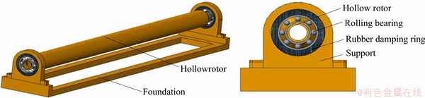
Figure 1 Three-dimensional model of coupling system
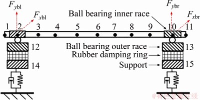
Figure 2 Finite element model of coupling system
3 System dynamic equations
3.1 Differential equations of rotor
Figure 3 shows the rotor��s mechanical model, where the bearing inner rings are fixed at both ends of the rotor and are subjected to the nonlinear bearing force. According to the analysis, the rotor dynamics equation includes the finite element modelling of the rotor and the force analysis of the ball bearing. The specific analysis is provided made below.
1) Finite element modelling of rotor
In this study, only the lateral vibration of the rotating shaft is considered. The Timoshenko beam element is utilized to discretise the shaft and establish its dynamic model. The schematic diagram of the Timoshenko beam element is shown in Figure 4. As indicated in Figure 4, each node has 4 degrees of freedom, which are the movement in the X and Y directions and the rotation around the X and Y directions. The element node��s displacement vector includes 8 degrees of freedom, and it can be expressed as

 .
.
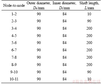
According to the literatures [33-35], the beam element mass matrix Me, stiffness matrix Ke, gyroscopic matrix Ge, and gravity matrix Qe can be obtained, respectively, as shown in Appendix, in which E is elastic modulus, G refers to the shear modulus, �� stands for the density, I indicates diametral inertia, A denotes the element��s cross-sectional area, �� represents Poisson ratio, L means the length of the element, mL is the shaft element mass, Do and Di are the outer and inner diameters of the element.
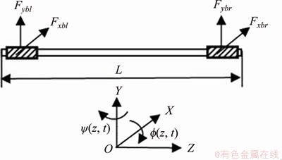
Figure 3 Mechanical model of rotor
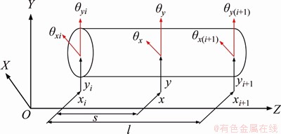
Figure 4 Schematic diagram of beam element
2) Force analysis of ball bearing
Figure 5 shows the ball bearing��s schematic diagram. ��cage represents the ball element��s angular velocity which can be given as follows:
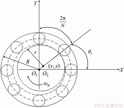
Figure 5 Ball bearing��s schematic diagram
 (1)
(1)
where ���� denotes the rotor��s angular velocity, while R indicates the bearing outer ring��s radius, and r represents the bearing inner ring��s radius.
The bearing��s nonlinear elastic forces can be described as [36]
 (2)
(2)
where


 represents a function of Haversian, Ns means the ball number and kp is the contact stiffness. When z=0 and z=L, the left bearing��s relative displacement can be given by
 and the right bearing��s relative displacement can be described as
 The bearing��selastic force, namely, Fkxbl, Fkybl, Fkxbr and Fkybr, can also be obtained from Eq. (2).
Through research, it is found that the bearing��s damping is mostly equivalent to Rayleigh damping, which can be written in the following form.
 (3)
(3)
When z=0 and z=L, the left bearing��s relative speed can be obtained by

 and the relative speed of right bearing is given by
 According to Eq. (3), the bearing outer ring��s damping force can be expressed as follows:
 (4)
(4)
Therefore, the nonlinear ball bearing forces applied to two ends of the rotor can be given by
 (j=l, r) (5)
Since the rotor��s coordinate system and the global coordinate system have the same direction, no spatial transformation is needed, and the beam element matrices Me, Ke, Ge and Qe can be assembled directly. The bearing��s inner ring mass (j=l, r) and the bearing��s nonlinear force Fbj (j=l, r) are integrated into the corresponding beam element node, and the rotor��s overall mass matrix Mr, overall stiffness matrix Kr, overall gyro matrix Gr and whole gravity matrix Qr can be acquired, respectively. Then, the rotor��s dynamic equations can be obtained as follows.
 (6)
(6)
where Cr represents the rotor��s Rayleigh damping matrix, i.e., 
3.2 Differential equations of bearing outer rings
The bearing outer ring establishes dynamic equations by the lumped mass method. Referring to Figure 2, the bearing outer ring is subjected to the bearing��s nonlinear force and the rubber damping ring��s force. At the same time, the rubber damping ring expresses the dynamic behaviors of the viscoelastic material, which can be represented by the Kelvin-Voigt linear mechanical model in engineering [37]. Thus, the rubber damping ring��s supporting force can be written as follows [38].
 (7)
(7)
where k* represents the rubber damping ring��s complex stiffness; u denotes the rubber damping ring��s relative displacement; k1 and �� are the rubber damping ring��s stiffness and loss factor, respectively.
The rubber damping ring��s relative displacement can be expressed as  and then Fs can be rewritten as [38]
 (8)
(8)
where x* and y* are the rubber damping ring��s relative displacements in X and Y directions, respectively.
Then, the forces of the rubber damping ring are solved by Eq. (8), which can be expressed as follows.
 (9)
(9)
where Fxsl, Fysl, Fxsr and Fysr are the rubber damping ring��s forces in the X and Y directions, respectively; xbl(t), ybl(t), xbr(t) and ybr(t) represent the left and right support��s displacement in the X and Y directions, respectively; xwl(t), ywl(t), xwr(t) and ywr(t) are the left and right bearing outer ring��s displacement in the X and Y directions, respectively.
Hence, the dynamic equations of the bearing outer rings could be obtained as follows:
 (10)
(10)
where mbwl and mbwr are the left and bearing outer race��s mass, respectively.
3.3 Differential equations of supports
The supports are bolted to the foundation in this study, and the bolt connection is equivalent to a mass-spring model, which are subjected to a linear spring force and damping force. According to the analysis, the supports are affected by the rubber damping ring��s reaction force and the equivalent spring and damping force of the bolt connection. According to Newton��s second law, the dynamic equations of the supports could be given by,
 (11)
(11)
where mbsl and mbsr represent the left and right support��s masses, respectively; kx1 and ky1 denote the support��s stiffness in the X and Y directions, respectively; cx1 and cy1 are the support��s damping in the X and Y directions, respectively.
3.4 Coupling equations of rotor system
Based on the rotor��s differential equations, the bearing outer ring��s differential equations and the support��s differential equations, the coupling equations of the flexible rotor supported by ball bearings with rubber damping rings can be given by,
 (12)
(12)
where


 and
and are the coupling system��s mass matrix, damping matrix, gyro matrix, stiffness matrix and generalized force matrix, respectively, while
 and X are the coupling system��s displacement, velocity and acceleration vectors, respectively.
Since the magnitude of the parameter values in the coupling system��s equations varies greatly, the system is dimensionless for the accuracy of the calculation. The dimensionless parameters are defined in this equation as follows:


 .
.
Equation (12) can be converted into the following.
 (13)
(13)
Also assume that 
 and
and  Then Eq. (13) can be changed to the formula below.
 (14)
(14)
4 Dynamic equation verification
Since the coupling dynamic equation in this research is a strong nonlinear system with many degrees of freedom, the precise integration and the Runge-Kutta hybrid numerical algorithm that solve not only nonlinear systems but also avoid iterative calculations is utilized to compute the coupling system��s dynamic equations [39, 40]. For the convenience of description, this paper mainly studies the vibration response of the rotor at the intermediate node. Suppose that the unbalance mass is applied at the intermediate node, and the product of the unbalance mass and diameter is taken as me=2��10-4 kg��m. The rubber damping ring��s stiffness and loss factor are k1=4��106 N/m and ��=0.08, respectively. The parameters of the rotor, ball bearing and bearing supporting are shown in Tables 1-3, respectively. At the same time, the elastic model E, Poisson ratio �� and density �� of the shaft are 6.8��1010 Pa, 0.3, 2700 kg/m3, respectively.
Table 1 Parameters of rotor
4.1 Comparison of test and simulation results
In order to verify the accuracy of the dynamic model, the mechanical model of the multi-span rotor test rig was established using the same modeling method as in this research, and compared with the experimental data. The multi-span rotor-bearing vibration test platform consists of a multi-span shafting system, a displacement sensor, a dynamic signal acquisition device and a computer, as shown in Figure 6; wherein the multi-span rotor-bearing system consists of a rotating shaft, an inertial disk, fixed support, a motor and so on.
An unbalance amount was applied at the rotor��s center node, and the vibration response of the rotor accelerated to 4000 r/min is analyzed.Figure 7 shows the experimental and simulated vibration responses of a multi-span rotor-bearing system with accelerated motion, respectively. It can be seen from the test that the first-order rotational speed of the rotor-bearing test platform is 3025 r/min. According to the dynamic model method of this research, the first-order critical speed of the rotor-bearing system obtained by the solution is 3225 r/min. Therefore, the mean error between the two findings is less than 10%. The above analysis shows that the multi-span shafting dynamic model established in this research has superior accuracy and can be used to predict the dynamic characteristics of the actual multi-span shafting system.
Table 2 Parameters of ball bearing
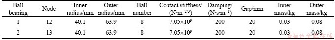
Table 3 Parameters of bearing supporting
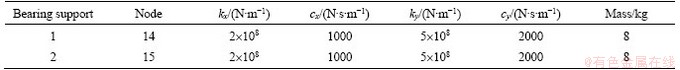
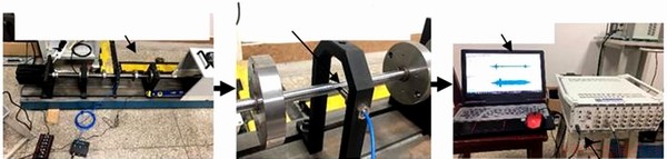
Figure 6 Multi-span rotor-bearing vibration test platform
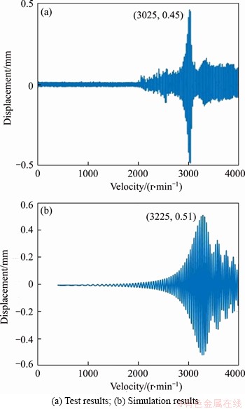
Figure 7 Vibration responses of real test and simulation during acceleration motion of rotor-bearing system:
4.2 Analysis of influence of rubber damping ring on coupling system
Firstly, when there is no rubber damping ring, the coupling system accelerates to 10000 r/min with acceleration ��=105 rad/s2; as can be observed from Figure 8(a), the amplitude of the vibration of the rotor-bearing system increases with the escalation of the rotational speed, which indicates the system is in a subcritical state at this stage. The overall supporting stiffness of the coupling system decreases when the rubber damping ring is installed in the rotor-bearing system. Therefore, the first- order critical speed is significantly reduced, and the system is in a supercritical state, as shown in Figure 8(b).
The stiffness of the rubber damping ring has been altered to 1.5��106 N/m, 3��106 N/m and 4��106 N/m, respectively, and the vibration response of the rotor-bearing system under the corresponding working conditions is analyzed, respectively, as shown in Figure 9(a); It can be observed from Figure 9 that the critical speed of the system also varies under different rubber damping ring��s stiffness; Altering the rubber damping ring��s stiffness can also adjust the critical speed of the rotor-bearing system. Similarly, the loss factors of the rubber damping ring are changed to 0.1, 0.2 and 0.4, respectively, and the vibration response of the rotor-bearing system under the corresponding working conditions is also calculated, as shown in Figure 9(b). Due to the damping effect of the rubber damping ring, the vibration response of the system is suppressed. By changing the loss factor of the rubber damping ring, the vibration reduction rate of the system is significantly varied. Through the above analysis, it also shows that the dynamic model of this research has high reliability.
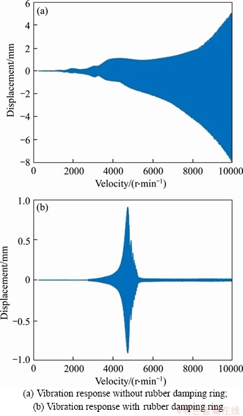
Figure 8 Vibration responses of a coupled system with and without rubber damping ring:
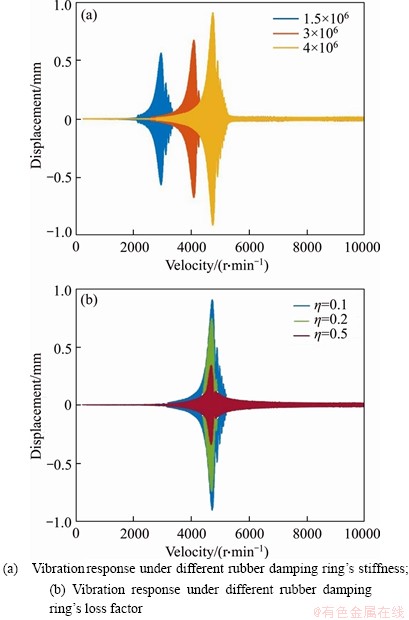
Figure 9 Analysis of influence of rubber damping ring on system dynamic characteristics:
5 Bifurcation and chaos analysis
5.1 Bifurcation and chaos analysis of effect of rotational speed
The ball bearing has a certain gap due to the installation and use, and the existence of the gap makes the system have a strong nonlinearity. Therefore, it is imperative to investigate the effect of bearing gap on the system��s bifurcation behaviors. Additionally, the rotational speed plays significant roles in the nonlinear behaviors of the complex rotor coupling system. Figure 10 shows the bifurcation properties of N with respect to X, when bearing clearance equals 10, 20, 40 and 60 ��m, respectively.
Figures 10(a) and (b) reveal the system��s bifurcation diagrams with the rotational speed. It can be seen from Figure 10(a) that due to the small bearing gap, the effect of the VC vibration is small, while the vibration effect caused by the unbalance force is relatively significant at a low rotation speed, and the system mainly exhibits 1T-periodic motion. By comparing Figures 10(a) and (b), it can be observed that the unbalance force and the nonlinear bearing force are simultaneously presented in the system as the speed increases, and the level of the magnitude of them is the same, so the motion mainly manifests as quasi-periodic motion in the range of the low speed. Under current parameters, the system��s first-order critical speed is 5200 r/min. Moreover, it should be noted that the system enters into chaos through quasi-periodic motion near the critical speed as illustrated in Figure 10(a), while in Figure 10(b) the system transfers into chaos through crisis changing from 1T-periodic motion near the critical speed, and at this time, the system motion becomes unpredictable, and the track never repeats. It always jumps from one track to another, which affects the stability of the rotor system. Furthermore, as shown in Figures 10(a) and (b), when the rotational speed is within the range of 5500-12000 r/min, the change of the system motion is between short and complicated periods (such as long period, quasi-period and chaos) in multiple rotational speeds. Due to the complexity of actual motion conditions, the working rotational speed of the system may fluctuate slightly. If the working speed of the system falls into the speed which corresponds to the above bifurcation points, the system motion becomes quickly unstable. As the rotational speed keeps elevating, the system motion becomes more stable than that of the low rotation speed because the VC vibration effect of the system is relatively small at a high rotation speed. Referring to Figures 10(c) and (d), it can be noted that as the bearing gap keeps growing, the VC vibration effect also increases continuously, and the system��s chaotic area at low rotation speed increases gradually, resulting in a deterioration in the stability of the system movement. Thus, selecting the appropriate bearing gap is of considerable significance to improve the stability of the system operation.
Through the Poincar�� maps, the system motion can be tracked and recorded with the change of bifurcation parameters, so that the evolution process of the motion state of the system can be qualitatively analyzed and understood. The overall bifurcation motion in Figure 10(b) is used as an example to explain the variation laws of the system motion state with the rotational speed, as shown in Figure 7.
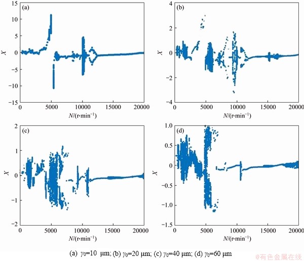
Figure 10 Bifurcation diagrams of system with different rotational speeds and bearing clearances:
Firstly, due to the interaction of VC vibration and unbalance force, the system mainly exhibits the quasi-periodic motion when N is below 2200 r/min, as shown in Figure 11(a). As N increases to the range of 2300-3500 r/min, it can be observed from Figures 11(b)-(e) that system motion enters into 1T-periodic motion under the effects of stable attractors, and then changes into 2T-period motion at N=3600 r/min, then bifurcates to 1T-period when N reaches to 4100 r/min. As shown in Figures 11(f)-(h), they demonstrate that the system motion undergoes Hopf bifurcation to form two constant attraction circles at N=4300 r/min, and then enters into period-two motion. Finally, the system switches to the period-one motion at N=4800 r/min.
Furthermore, when N increases to the range of 4800-5100 r/min, by combining Figures 10(b) and 12(a), the system motion suddenly jumps from the periodic-one movement to chaos as the rotational speed varies slowly. The process shows the typical characteristic of an abrupt change, proving that the system enters into chaos through the crisis. Since transferring to chaotic motion by the channel of crisis occurs mostly in the clearance, the existence of the bearing gap of the complex rotor coupling system is the main reason for the system to enter into the chaos through the crisis. Within the range of 5100-8800 r/min, the system undergoes 8T-period, 6T-period and 2T-period, respectively, and then converges to periodic-one motion at N=8800 r/min after experiencing the width of the region of chaotic motion, as observed in Figures 12(b)-(f). However, when N locates at the range of 9400-10100 r/min, there exist multiple periodic windows in chaotic motion, which is a transition path between chaotic motion and periodic motion. It is a typical intermittent chaotic motion, as shown in Figures 12(g)-(l). The system is attracted by a stable attractor, and it enters a stable orbit and moves from quasi-periodic to 1T-periodic when N reaches to 10200 r/min. As N increased from 10600 r/min to 12000 r/min, the system undergoes Hopf bifurcation to form two attraction circles, and then enters into 2T-periodic motion at N=11000 r/min, and finally enters into the stable 1T-period through inverse bifurcation, as shown in Figures 12(m)-(r). However, the system moves from 1T-period to quasi-period motion when N increases to 14300 r/min, as shown in Figure 12(s). Finally, as N is within the range of 17200-18000 r/min, the system is attracted by the stable attractor and enters the stable orbit by quasi- periodic motion, and then reverts to a 1T-periodic motion. Figures 12(t)-(x) illustrate the 4-mode shape of the system under the effect of a stable attractor, which causes the stable attractant domain to shrink as the rotational speed increases.
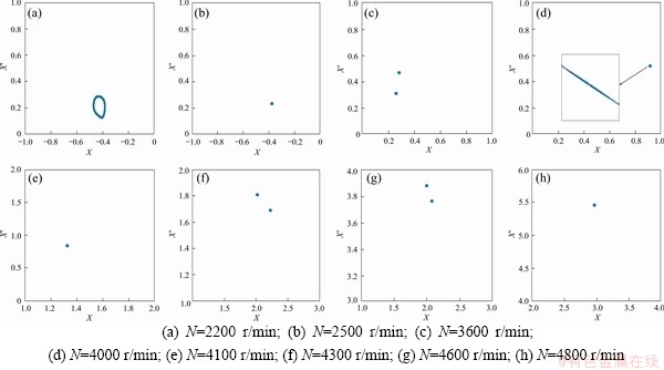
Figure 11 Poincar�� maps with different rotation speeds:
By combining the bifurcation diagrams Figure10, the Poincar�� maps Figures 11 and 12, the nonlinear behaviors and bifurcation characteristics of the complex rotor coupling system could be studied, and the bifurcation point and corresponding critical transition speed of the system under various parameters can be obtained, thus adjusting the structure or working condition of the transmission system to avoid unstable motion transition. This method has important applications and reference values in improving the motion stability and fatigue life of the rotor system.
5.2 Bifurcation and chaos analysis of effect of rubber damping ring��s stiffness
The rubber damping ring plays an important role in the coupling system. Adjusting the damping ring��s stiffness can change the natural frequency and vibration mode, but it may reduce the stability of the rotor. Rubber damping rings with different characteristics can be obtained by different rubber material and processing parameters. The study of bifurcation characteristics of rubber damping rings is helpful to guide the design of damping ring parameters. Therefore, it is vital to conduct a detailed study on the influence of the rubber damping ring��s parameter on the dynamic behaviors of the system.
Under different bearing clearances, the bifurcation diagrams of k1 with respect to X are acquired in Figure 9 at the rotational speed N=4200 r/min and damping ring��s loss factor ��=0.08. It can be shown from the bifurcation diagrams that the damping ring��s stiffness has a strong coupling effect on the system motion. As can be seen from Figure 13(a), when k1 locates in the range of 0.4��106 to 4��106 N/m, the system presents diversified motion transitions. The system is mainly in stable 1T-periodic motion when k1 is small. With the increase of k1, the system performs the bifurcation between short-period and long-period motion states at 2.3��106 N/m, 2.5��106 N/m, 2.72��106 N/m, 2.8��106 N/m, 2.86��106 N/m, and 3��106 N/m, respectively. It should be noted that as k1 increases from 3.28��106 to 3.7��106 N/m, quasi-periodic and chaotic motion appears in the system. Finally, it reverts to 1T-periodic motion through the inverse bifurcation. By the same method, the overall bifurcation diagram of the system motion can be obtained in different bearing gaps ��0=20 ��m, ��0=40 ��m and ��0=60 ��m, respectively. By comparing Figures 13(a)-(d), it is found that when the bearing gap is relatively small, the system will eventually return to stable 1T-periodic motion with the increase of k1; however, the bearing gap is excessive, the system��s vibration response will greatly deteriorate with increasing the damping ring��s stiffness, and the system will eventually progress towards chaos.
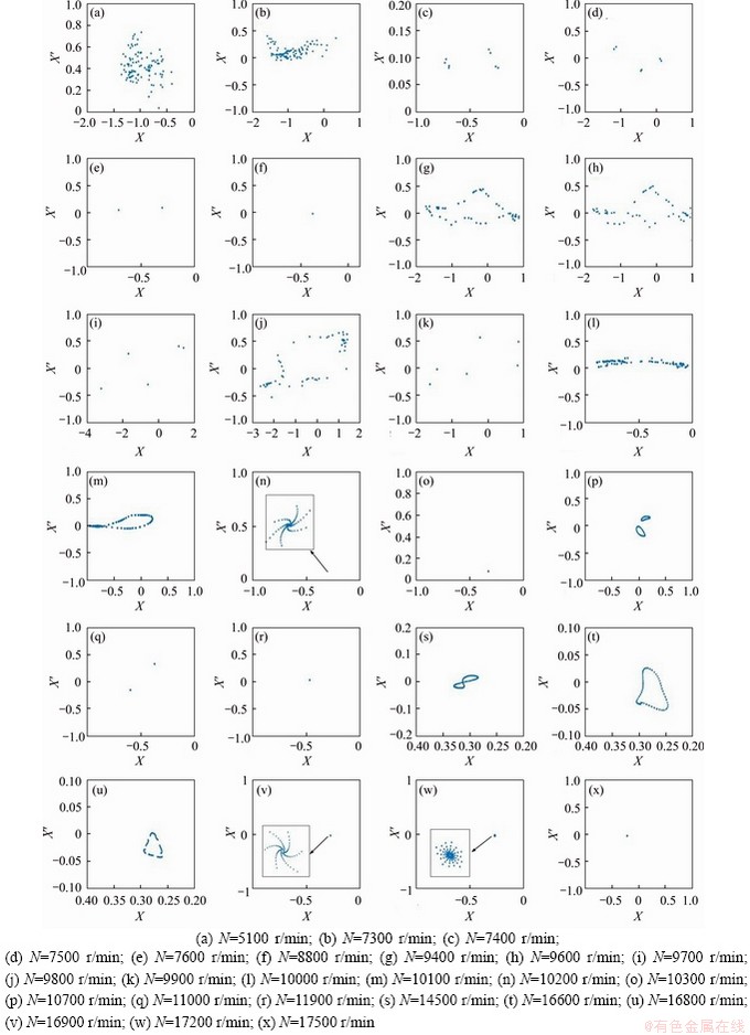
Figure 12 Poincar�� maps with different rotational speeds:
Likewise, the Poincar�� maps of X with respect to X�� at the given bearing gap ��0=20 ��m, rotational speed N=4200 r/min and damping ring��s loss factor ��=0.08 are plotted in Figure 10 to explain the change laws of the motion forms of the system. Obviously, within the range of 0.4��104-0.6��106 N/m, the system begins with a transient period-one motion, and then undergoes two times Hopf bifurcations to form three constant attraction circles at k1=0.46��106 N/m, and finally breaks into chaos under the effect of unstable attractors. Subsequently, system motion enters into a transient 2T-period motion through inverse bifurcation when k1 reaches 0.52��106 N/m, and the t moves from 2T-period to 1T-period at k1=0.6��106 N/m, as shown in Figures 14(a)-(e). As k1 gradually increases to the range of 0.62��106-1.2��106 N/m, the system switches to quasi-periodic motion after going through periodic-one motion at k1=0.7��106 N/m, and then quasi-periodic torus breaks up and transfers to chaos; However, as k1 increases to 0.8��106 N/m, the chaotic motion is replaced by the period-two motion, and then converges to 1T-periodic motion, as shown in Figures 14(f)-(j). Furthermore, within the range of 1.22��106 N/m<>1< 2.02��106 N/m, the system forms two constant attraction circles through Hopf bifurcation at k1=1.38��106 N/m and enters into the 2T-period motion later. Then, under the effect of stable attractors, the system goes into stable 1T-periodic motion, as shown in Figures 14(k)-(n). As k1 in the range of 2.04��106 to 2.58��106 N/m, the system motion undergoes 2T-period motion and Hopf bifurcation at k1=2.26��106 N/m and k1=2.3��106 N/m, respectively, and then converges to period-one when k1=2.46��106 N/m, as shown in Figures 14(o)- (r). By combining Figures 13(b) and 14(s), it indicates that system motion changes from 1T-periodic to the chaotic motion with a certain width by way of crisis within the range of 2.8��104-3.66��106 N/m. Subsequently, the system moves from chaos to quasi-periodic motion through inverse bifurcation at k1=3.68��106 N/m, then bifurcates to a 2T-periodic motion. When k1 reaches 3.76��106 N/m, the system forms two constant attraction circles through Hopf bifurcation from 2T-periodic motion, and then enters into quasi-periodic motion again under the effort of stable attractors, and finally reverts to 1T-periodic motion, as shown in Figures 14(t)-(x).
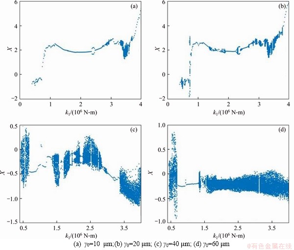
Figure 13 Bifurcation diagram of system with different damping ring stiffness, bearing clearance:
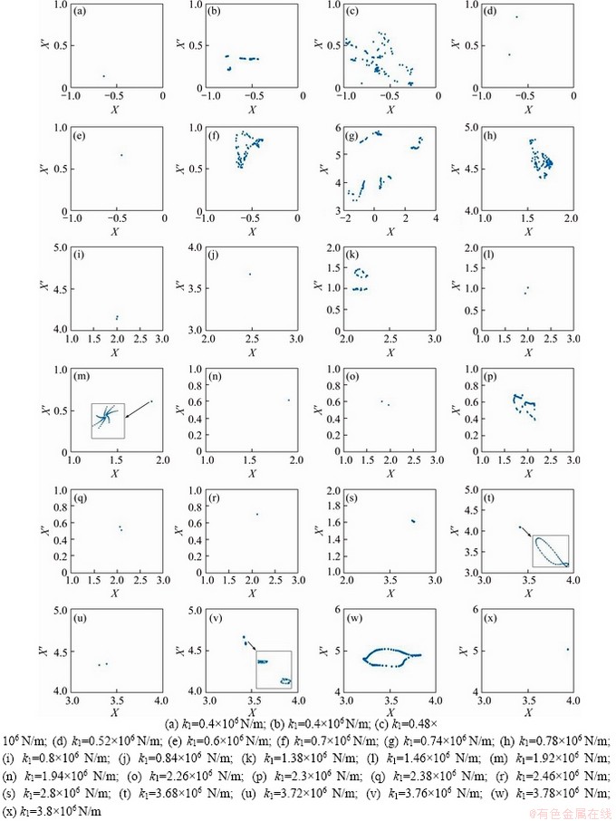
Figure 14 Poincar�� maps with different damping ring stiffnesses:
Summarizing the above research, the motion state of the system presents complicated bifurcation behaviors under various bearing clearances and damping ring��s stiffness, and it also can be found that the state of the system motion changes into chaos through various ways under different damping ring��s stiffness, including crisis, quasi-periodic surface rupture, and surface rupture after Hopf bifurcation. The proper bearing gap exerts a weak effect on the periodicity of the system motion, while the excessive bearing gap leads to a larger chaotic motion range of the system. Meanwhile, the change of the damping ring��s stiffness shows a significant effect on the system motion. Choosing a reasonable damping ring stiffness is favorable to the stable operation of the rotor.
6 Conclusions
This research establishes a coupling dynamic model of a flexible rotor supported by ball bearings with rubber damping rings. In the proposed model, the rotor is built by Timoshenko beam element, and the supports and bearing outer rings are yielded by the lumped mass method. Subsequently, the coupling system��s equation is solved by precise integration and the Runge-Kutta hybrid numerical method.
The accuracy measure of the modelling method in this research is carried out by multi-span rotor-bearing test platform, in which the error rate between theoretical and experimental analysis results is less than 10%. Meanwhile, the rubber damping ring��s effect on the dynamic properties of the rotor-bearing coupling system is analyzed, in which conclusions obtained are in agreement with the real-world scenarios. Therefore, the dynamic model constructed has superior accuracy and efficiency.
The bifurcation and chaos behaviors of the system under the parameters of rotational speed and damping ring��s stiffness are analyzed. Through the study of various parameters, the following conclusions could be drawn as follows.
1) Under the bifurcation parameter of rotational speed, the system goes into chaos by way of crisis, period doubling, quasi-periodic and intermittent bifurcation. By comparing the bifurcation diagrams of various bearing gaps, it can be revealed that excessive bearing clearances would lead to continuous chaotic motion of the system at low rotational speeds, which seriously affects the system��s stability. Hence, it is crucial to effectively control the bearing clearance during the design and use of the system.
2) Under a specific bearing gap and rotational speed, the change of the parameters of the rubber damping ring exerts an effect on the bifurcation behaviors of the system motion. As the damping ring��s stiffness increasing, the routes of the system enter chaos include crisis, quasi-periodic and Hopf bifurcation. When the bearing clearance is small, the system will eventually return to stable 1T-periodic motion through inverse bifurcation, and finally, the chaotic movement is performed with the gradual increase of the damping ring��s stiffness under the larger bearing clearance.
Appendix

where


 .
.
 .
.
 .
.
where


 .
.
Contributors
ZHU Hai-min, CHEN Wei-fang, and ZHU Ru-peng established the models and calculated the predicted displacement. ZHANG Li edited the draft of manuscript. GAO Jie and LIAO Mei-jun provided the measured landslides displacement data, and analyzed the measured data. All authors replied to reviewers�� comments and revised the final version.
Conflict of interest
ZHU Hai-min, CHEN Wei-fang, ZHU Ru-peng, ZHANG Li, GAO Jie and LIAO Mei-jun declare that they have no conflict of interest.
References
[1] FUKATA S, GAD E H, KONDOU T, AYABE T, TAMURA H. On the radial vibration of ball bearings (computer simulation) [J]. Bulletin of the JSME, 1985, 28: 899-904. DOI: 10.1299/jsme1958.28.899.
[2] KIM Y B, NOAH S T. Bifurcation analysis for a modified Jeffcott rotor with bearing clearances [J]. Nonlinear Dynamics, 1990, 1: 221-241. DOI: 10.1007/BF01858295.
[3] TIWARI M, GUPTA K, PRAKASH O. Dynamic response of an unbalanced rotor supported on ball bearing [J]. Journal of Sound and Vibration, 2000, 238(5): 757-779. DOI: 10.1006/jsvi.1999.3108.
[4] HARSHA S P, SANDEEP K, PRAKASH R. Non-linear dynamic behaviors of rolling element bearings due to surface waviness [J]. Journal of Sound and Vibration, 2004, 272: 557-580. DOI: 10.1016/S0022-460X(03)00384-5.
[5] HARSHA S P. Nonlinear dynamic response of a balanced rotor supported by rolling element bearings due to radial internal clearance effect [J]. Mechanism and Machine Theory, 2006, 41(6): 688-706. DOI: 10.1016/j.mechmachtheory. 2005.09.003.
[6] MEVEL B, GUYADER J L. Experiments on routes to chaos in ball bearings [J]. Journal of Sound and Vibration, 2008, 318(3): 549-564. DOI: 10.1016/j.jsv.2008.04.024.
[7] BAI C Q, XU Q Y. Dynamic model of ball bearings with internal clearance and waviness [J]. Journal of Sound and Vibration, 2006, 294: 23-48. DOI: 10.1016/j.jsv.2005. 10.005.
[8] CHAVEZ P J, WIERCIGROCH M. Bifurcation analysis of periodic orbits of a non-smooth Jeffcott rotor model [J]. Communications in Nonlinear Science and Numerical Simulation, 2013, 18: 2571-2580. DOI: 10.1016/ j.cnsns.2012.12.007.
[9] HOU L, CHEN Y S, CAO Q J, ZHANG Z Y. Turning maneuver caused response in an aircraft rotor-ball bearing system [J]. Nonlinear Dynamics, 2015, 79(1): 229-240. DOI: 10.1007/s11071-014-1659-8.
[10] CHEN G, LI C G, WANG D Y. Nonlinear dynamic analysis and experiment verification of rotor-ball bearings-support- stator coupling system for aeroengine with rubbing coupling faults [J]. Journal of Engineering for Gas Turbines and Power-transactions of the ASME, 2009, 132(2): 1-9. DOI: 10.1115/1.2940355.
[11] CHEN G. Vibration modelling and verifications for whole aero-engine [J]. Journal of Sound and Vibration, 2015, 349: 163-176. DOI: 10.1016/j.jsv.2015.03.029.
[12] CHEN G. Simulation of casing vibration resulting from blade�Ccasing rubbing and its verifications [J]. Journal of Sound and Vibration, 2016, 361: 190-209. DOI: 10.1016/ j.jsv.2015.09.041.
[13] WANG H F, GONG J J, CHEN G. Characteristics analysis of aero-engine whole vibration response with rolling bearing radial clearance [J]. Journal of Mechanical Science and Technology, 2017, 37: 2129-2141. DOI: 10.1007/s12206- 017-0409-5.
[14] LIU X J, LIU Y, WANG S G, YAN H J, LIAO P T. Bifurcation analysis of a magnetically supported rigid rotor in auxiliary bearings [J]. Chaos, Solitons & Fractals, 2019, 118: 328-336. DOI: 10.1016/j.chaos.2018.11.034.
[15] HAN Y C, LI M. Nonlinear dynamic characteristics of marine rotor-bearing system under heaving motion [J]. Shock and Vibration, 2019: 1-16. DOI: 10.1155/2019/ 7683952.
[16] WANG A M, YAO W, HE K, MENG G Y, CHENG X H, YANG J. Analytical modelling and numerical experiment for simultaneous identification of unbalance and rolling-bearing coefficients of the continuous single-disc and single-span rotor-bearing system with Rayleigh beam model [J]. Mechanical Systems and Signal Processing, 2019, 116: 322-346. DOI: 10.1016/j.ymssp.2018.06.039.
[17] ALVES D S, WU M F, CAVALCA K L. Application of gain-scheduled vibration control to nonlinear journal-bearing supported rotor [J]. Mechanical Systems and Signal Processing, 2019, 442: 714-737. DOI: 10.1016/j.jsv. 2018.11.027.
[18] YANG Y, YANG Y R, CAO D Q, CHEN G, JIN Y L. Response evaluation of imbalance-rub-pedestal looseness coupling fault on a geometrically nonlinear rotor system [J]. Mechanical Systems and Signal Processing, 2019, 118: 423-442. DOI: 10.1016/j.ymssp.2018.08.063.
[19] DONG J, WANG X J, ZHAN G J, GU J J. Experimental investigation of dynamic behaviour of rotor-bearing system with nitrile rubber support [J]. Proceedings of the Institution of Mechanical Engineers Part C. Journal of Mechanical Engineering Science, 2018, 232: 1502-1513. DOI: 10.1177/1350650118757067.
[20] SAEED N A, EISSA M. Bifurcations of periodic motion of a horizontally supported nonlinear Jeffcott rotor system having transversely cracked shaft [J]. International Journal of Non-linear Mechanics, 2018, 101: 113-130. DOI: 10.1016/ j.ijnonlinmec.2018.02.005.
[21] PENG B, ZHU RP, LI M M, TANG Z Y. Bending vibration suppression of a flexible multispan shaft using smart spring support [J]. Shock and Vibration, 2017: 1-12. DOI: 10.1155/2017/7859164.
[22] MARAINI D, NATARAJ C. Nonlinear analysis of a rotor-bearing system using describing functions [J]. Journal of Sound and Vibration, 2018, 420: 227-241. DOI: 10.1016/j.jsv.2018.01.018.
[23] HAN B B, DING Q. Forced responses analysis of a rotor system with squeeze film damper during flight maneuvers using finite element method [J]. Mechanism and Machine Theory, 2018, 122: 233-251. DOI: 10.1016/ j.mechmachtheory.2018.01.004.
[24] LIU J. A comprehensive comparative investigation of frictional force models for dynamics of rotor-bearing systems [J]. Journal of Central South University, 2020, 27: 1770-1779. DOI: 10.1007/s11771-020-4406-y.
[25] CHOUKSEY M, DUTT J K, MODAK S V. Modal analysis of rotor-shaft system under the influence of rotor-shaft material damping and fluid film forces [J]. Mechanism and Machine Theory, 2012, 48: 81-93. DOI: 10.1016/ j.mechmachtheory.2011.09.001.
[26] MIRTALAIE S H, HAJABASI M A. Nonlinear axial-lateral-torsional free vibrations analysis of Rayleigh rotating shaft [J]. Archive of Applied Mechanics, 2017, 87(9): 1465-1494. DOI: 10.1007/s00419-017-1265-6.
[27] LU X, ZHANG J H, MA L, LIN J W, WANG J, WANG J, DAI H W. Effects of misalignment on the nonlinear dynamics of a two-shaft rotor-bearing-gear coupling system with rub-impact fault [J]. Journal of Vibroengineering, 2017, 19: 5960-5977. DOI: 10.21595/jve.2017.18476.
[28] NAN G F, TANG M, CHEN E Y, YANG A L. Nonlinear dynamic mechanism of rolling element bearings with an internal clearance in a rotor-bearing system [J]. Advances in Mechanical Engineering, 2016, 8(11): 1-9. DOI: 10.1177/ 1687814016679588.
[29] TADAYOSHI S. Nonlinear vibration of saturated water journal bearing and bifurcation analysis [J]. Journal of Vibration and Acoustics, 2019, 141(2): 1-10. DOI: 10.1115/1.4042041.
[30] XU Y Y, CHEN Z B, LUO A C J. Period-1 motion to chaos in a nonlinear flexible rotor system [J]. International Journal of Bifurcation and Chaos, 30(5): 1-24. DOI: 10.1142/ S0218127420500777.
[31] HASLAM A H, SCHWINGSHACKL C W, RIX A I J. A parametric study of an unbalanced Jeffcott rotor supported by a rolling-element bearing [J]. Nonlinear Dynamics, 2020, 99(4): 2571-2604. DOI: 10.1007/s11071-020-05470-4.
[32] ZHU H M, CHEN W F, ZHU R P, GAO J, LIAO M J. Study on the dynamic characteristics of a rotor bearing system with damping rings subjected to base vibration [J]. Journal of Vibration Engineering & Technologies 2020, 8: 121-132. DOI: 10.1007/s42417-019-00082-8.
[33] FRISWELL M I, PENNY J E T, GARVEY S D, LEES A W. Dynamics of rotating machines [M]. London: Cambridge University Press, 2010.
[34] YOKOYAMA T. Vibrations of a hanging Timoshenko beam under gravity [J]. Journal of Sound and Vibration, 1990, 141: 245-258. DOI: 10.1016/0022-460X(90)90838-Q.
[35] YOKOYAMA T. Vibration analysis of Timoshenko beam-columns on two-parameter elastic foundations [J]. Computer and Structures, 1996, 61: 995-1007. DOI: 10.1016/0045-7949(96)00107-1.
[36] HARRIS T A. Rolling bearing analysis [M]. New York: John Wiley & Sons, 2003.
[37] FEI Z X, TONG S G, WEI C. Investigation of the dynamic characteristics of a dual rotor system and its start-up simulation based on finite element method [J]. Journal of Zhejiang University-Science A, 2013, 14(4): 268-280. DOI: 10.1631/jzus.A1200298.
[38] XUAN Hai-jun, HONG Wei-rong. Application of elastomeric O-rings damper in high-speed spin tester [J]. Journal of Zhejiang University(Engineering Science), 2005, 39(12): 1854-1857. DOI: 10.13197/j.eeev.2016.04.19. zhouy.003. (in Chinese)
[39] FANG X, ZHANG D B, ZHANG X Y, WU H C, GAO F, HE L, LV Y. Chaos of flexible rotor system with critical speed in magnetic bearing based on the improved precise Runge-Kutta hybrid integration [J]. Advances in Mechanical Engineering, 2018, 10(9): 1-14. DOI: 10.1177/ 1687814018800859.
[40] ZHANG S Y, DENG Z C, LI W C. A precise Runge-Kutta integration and its application for solving nonlinear dynamical systems [J]. Applied and Computational Mathematics, 2007, 184(2): 496-502. DOI: 10.1016/ j.amc.2006.06.054.
(Edited by HE Yun-bin)
���ĵ���
��������Ԫ�ͼ����������Ĵ����ỷ�������֧�ŵ�����ת�Ӷ���ѧ����
ժҪ��������Ԫ���������з����ϣ������˾��������ỷ�������֧�е�����ת�ӵĶ���ѧģ�͡��ڸ�ģ���У�ת��ͨ��Timoshenko����Ԫ��ɢ��ģ��֧���������Ȧ�����������з���ģ��ͬʱ������ת����������ƽ�����ͷ������������Ӱ�졣����ѧ���̲��þ�ȷ���ֺ�Runge-Kutta�����ֵ�㷨��⡣Ϊ����֤��ģ��������ȷ�ԣ���ת��-�������̨�Ͻ��������ۺ�ʵ�����������������ʵ���о��������С��10%�����⣬�������������ỷ��ת��-������ϵͳ����ѧ���Ե�Ӱ�죬���ý�����ʵ��������Ǻϡ��ڴ˻����ϣ��ֱ��о���ת�ٺ������ỷ�նȶ����ϵͳ�ķֲ��ͻ�����Ϊ��Ӱ�졣�������������ת�ٵ����ӣ�ϵͳ�������״̬��·���м��䡢�����ںͼ�Ъ�Էֲ���Ȼ�������������ỷ�նȵı仯�������˼��䡢�����ڷֲ���Hopf�ֲ��������;�������⣬��м�϶��ת��ϵͳ�Ķ�̬����Ҳ��Ӱ�죬�������м�϶��ʹϵͳ�������˶���Ϊ���磻�����ỷ�ĸնȶ�ϵͳ���˶��кܴ��Ӱ�졣
�ؼ��ʣ�����Ԫ����Timoshenko����Ԫ�������ỷ���ֲ�������
Foundation item: Projects(51775277, 51775265) supported by the National Natural Science Foundation of China; Project(190624DF01) supported by Nanjing University of Aeronautics and Astronautics Short Visiting Program, China
Received date: 2020-04-06; Accepted date: 2020-08-31
Corresponding author: CHEN Wei-fang, PhD, Professor; Tel: +86-18252002433; E-mail: meewfchen@nuaa.edu.cn; ORCID: https:// orcid.org/0000-0003-1604-7068
Abstract: A dynamic model of a flexible rotor supported by ball bearings with rubber damping rings was proposed by combining the finite element and the mass-centralized method. In the proposed model, the rotor was built with the Timoshenko beam element, while the supports and bearing outer rings were modelled by the mass-centralized method. Meanwhile, the influences of the rotor��s gravity, unbalanced force and nonlinear bearing force were considered. The governing equations were solved by precise integration and the Runge-Kutta hybrid numerical algorithm. To verify the correctness of the modelling method, theoretical and experimental analysis is carried out by a rotor-bearing test platform, where the error rate between the theoretical and experimental studies is less than 10%. Besides that, the influence of the rubber damping ring on the dynamic properties of the rotor-bearing coupling system is also analyzed. The conclusions obtained are in agreement with the real-world deployment. On this basis, the bifurcation and chaos behaviors of the coupling system were carried out with rotational speed and rubber damping ring��s stiffness. The results reveal that as rotational speed increases, the system enters into chaos by routes of crisis, quasi-periodic and intermittent bifurcation. However, the paths of crisis, quasi-periodic bifurcation, and Hopf bifurcation to chaos were detected under the parameter of rubber damping ring��s stiffness. Additionally, the bearing gap affects the rotor system��s dynamic characteristics. Moreover, the excessive bearing gap will make the system��s periodic motion change into chaos, and the rubber damping ring��s stiffness has a substantial impact on the system motion.
