
Trans. Nonferrous Met. Soc. China 27(2017) 1338-1352
3D FEM simulations and experimental validation of plastic deformation of pure aluminum deformed by ECAP and combination of ECAP and direct extrusion
Mohamed Ibrahim Abd EL AAL1,2
1. Mechanical engineering Department College of Engineering, Prince Sattam Bin Abdulaziz University, Wadi Addawasir, Kingdom of Saudi Arabia;
2. Mechanical Design & Production Department, Faculty of Engineering, Zagazig University, Zagazig, Egypt
Received 13 April 2016; accepted 10 September 2016
Abstract:
Rigid-viscoplastic 3D finite element simulations (3D FEM) of the equal channel angular pressing (ECAP), the combination of ECAP + extrusion with different extrusion ratios, and direct extrusion of pure aluminum were performed and analyzed. The 3D FEM simulations were carried out to investigate the load-displacement behavior, the plastic deformation characteristics and the effective plastic strain homogeneity of Al-1080 deformed by different forming processes. The simulation results were validated by microstructure observations, microhardness distribution maps and the correlation between the effective plastic strain and the microhardness values. The 3D FEM simulations were performed successfully with a good agreement with the experimental results. The load-displacement curves and the peak load values of the 3D FEM simulations and the experimental results were close from each other. The microhardness distribution maps were in a good conformity with the effective plastic strain contours and verifying the 3D FEM simulations results. The ECAP workpiece has a higher degree of deformation homogeneity than the other deformation processes. The microhardness values were calculated based on the average effective plastic strain. The predicted microhardness values fitted the experimental results well. The microstructure observations in the longitudinal and transverse directions support the 3D FEM effective plastic strain and microhardness distributions result in different forming processes.
Key words:
equal channel angular pressing (ECAP); extrusion; finite element method (FEM); microhardness; deformation homogeneity; microstructure;
1 Introduction
Severe plastic deformation (SPD) is one of the most popular techniques used in producing nanocrystalline (NC), ultra-fine grain (UFG) and sub-micron bulk workpieces. The large bulk sizes of processed samples make ECAP the most applied SPD technique. ECAP process principles were discussed briefly in previous works [1,2]. Al and its alloys are used widely in different applications such as automotive and aircraft industries due to their lightweight. Al and Al alloys workpieces processed by equal channel angular pressing (ECAP) with fine grain microstructures, which led to improvement in the mechanical and physical properties, have been an important focus of research in last two decades [3-5]. Recently, the combination of SPD and conventional deformation processes especially extrusion or between SPD processes was the motivation of different previous works [6-12].
Finite element method (FEM) is a numerical method that can be used effectively in the explanation of the deformation behavior during different deformation processes. FEM simulations were carried out successfully for the ECAP process [13-16]. The plastic deformation analysis [13], the selection and design of ECAP dies [14,15], and the tracing of the corner gap formation [13-16] were studied by FEM. However, most of the previous works of the FEM simulations of the ECAP were done by two dimensions (2D) FEM simulations [13-16]. Recently, the three-dimensional (3D) FEM simulations have been used efficiently in the analysis of effective plastic strain distribution and assessment of the deformation homogeneity during ECAP process [17-21]. The 3D FEM simulation is considered to be more reliable in the FEM simulation of the circular ECAP workpieces than the 2D FEM plane strain, plane stress, and axi-symmetric simulations [17,18]. Unfortunately, few of the previous works focused on the simulation of the plastic deformation of the combination of ECAP and other deformation processes. The previous works include the investigation of the plastic deformation in the combination of ECAP and extrusion, forging and twist extrusion [22-25]. Although the combination of ECAP + extrusion was modeled by 2D and 3D FEM simulations [22,25]. But, the FEM simulation results of the combination of ECAP + extrusion were not verified by experimental results such as mechanical properties and microstructure observations [22,25].
The lack of the previous studies that verified the FEM simulations of ECAP and the combination of ECAP + extrusion experimentally was the motivation for the present work. The present research aims to achieve the following objectives. First, the load-displacement behavior, the plastic deformation characteristics and the effective plastic strain homogeneity of Al-1080 deformed by the ECAP, the combination of the ECAP + extrusion, and direct extrusion numerically by 3D FEM simulations were studied. Second, the FEM results were verified experimentally using the experimental load- displacement curves, microhardness distributions maps, microhardness homogeneity and microstructure observations. Third, the microhardness values were estimated through the correlation between the effective plastic strain and the microhardness values in each case.
2 Finite element simulation
In the present study, a 3D FEM model was considered and performed to obtain the load- displacement curves and the effective plastic strain distribution maps of Al-1080 deformed by the ECAP, the combination of ECAP + extrusion and direct extrusion. The rigid-viscoplastic 3D finite element simulations were carried out using the commercial software DEFORM-3D V.6.1 [26]. DEFORM-3D is a finite element method (FEM) program based on the process simulation system to analyze different metal forming processes. Unlike, most FEM software DEFORM-3D provided an easy graphical interface that provides easy data preparation and analysis. DEFORM-3D program consists mainly of three components. First, the pre-processor, where the forming process parts created, assembled, or even modified the data required in the simulation, and generating the database file. The second part is the simulation module where the calculations needed to analyze the forming process and writing of the results to the database file are performed. The simulation module reads the database file, performs the actual solution calculation, and appends the appropriate solution data to the database file. Furthermore, the simulation module enables the automatic mesh generation (AMG) system to generate a new FEM mesh. The third part is the post processor that allows reading the database from the simulation module and displays the results graphically and for extracting numerical data.
The DEFORM-3D pre-processing step includes different steps as follows. First, upload and check the workpiece geometry. In the present work, the workpieces used in the simulation have a cylindrical shape with a diameter of 15 mm and a length of 80 mm. The workpiece geometry was drawn by 3D CAD program Solid Works V.2014. The workpiece geometry was saved in the STL format that can be uploaded, read, and checked by DEFORM-3D V.6.1. The second step is uploading the workpiece material characteristics. The workpiece was considered to be a rigid-plastic body [21,27]. The workpiece material characteristics required in DEFORM-3D V.6.1 were obtained from the flow stress equation as
��=k��n (1)
where ��, k, �� and n are the flow stress, strength coefficient, effective tensile strain, and strain hardening exponent, respectively. The workpiece material tensile characteristics were obtained from previous work [10]. The tensile characteristics of the workpiece material were loaded in a tabular form and saved in the material library in the DEFORM-3D. The simulation temperature was considered as room temperature, like the experimental work, 20 ��C. The third step in the pre-processing is the workpiece meshing process. The workpiece was meshed into 20000 four-node elements, which is considered sufficient relative to the work volume or even higher than those used in previous works of 2D or 3D FEM simulations [16,19-21,28]. The 20000 four-node elements used in the present work were higher than those of 1520, 4183, 16000, 10000, and 2800 used in the meshing of workpieces with equal or even larger volumes than that of the workpiece used in the present work [16,19-21,28]. The mesh was automatically re-meshed if the elements became too distorted during the forming process simulations. The fourth step in the pre-processing is the die and the punch drawing and loading into the program in the same way used in the case of the workpiece. Figure 1 shows the drawing of the different dies used in the present work. The dies and the punches were made of high strength steel in the present work. Therefore, the dies and the punch were modeled as rigid surfaces.
Finally, the contact boundary conditions and the coefficient of friction among the die, punch, and the workpiece were applied. The contact boundary conditions among the die, the punch, and the workpiece can automatically generate. The tolerance between the die and punch on one side and the workpiece on the other side can be obtained automatically by DEFORM-3D and then the contact nodes are generated. Then, the value of the coefficient friction between the die and punch on one side and the workpiece on the other side can be set depending on the forming process condition. The workpiece top surface is in a complete contact with the punch which moves with a constant speed of 1 mm/s. The friction coefficient with a nominal value of 0.12 was assumed in the present work. First, this value is the minimum stander value of the friction coefficient during cold forming of Al [29]. Second, the friction coefficient value of 0.12 is recommended during the cold forming using a steel die in DEFORM-3D V.6.1 [26]. Third, the friction coefficient of 0.12 is less than 0.2 that is considered as the maximum allowable limit of the friction coefficient value to complete the FEM simulations of ECAP with the formation of a reasonable steady state zone and a good degree of deformation homogeneity [30].
The effective plastic strain distributions maps were obtained in mid-length of the workpiece in the transverse direction as shown in Fig. 2(f). Moreover, the effective plastic strain distribution maps were also obtained in the middle plane of the workpiece parallel to the longitudinal axis as shown in Fig. 2(f). The standard deviation ���� of the effective plastic strain in each case was used to assess the deformation inhomogeneity index in the transverse direction from the following equation:
 (2)
(2)
where ��i and ��av and N�� denote the effective plastic strain value at each point, the average effective plastic strain value and the total number of strain values, respectively.
3 Experimental
Commercially pure Al-1080 workpieces with chemical composition as indicated in Table 1 were used in the present work. The Al-1080 workpieces were machined into a cylindrical shape with a diameter of 15 mm and a length of 80 mm. Split dies were constructed for ECAP and the combination of ECAP + extrusion processes and a solid die for the direct extrusion process as shown in Fig. 1. ECAPed workpiece was processed up to one pass using a split die with an inner diameter of 15 mm, an inner die angle (��) of 90��, and an outer arc angle (��) of 15�� as shown in Fig. 1(a).
The combination of ECAP + extrusion was carried out through an integrated die in one step. The ECAP process was followed by the direct extrusion process with extrusion ratios of 2 and 8 as shown in Figs. 1(b) and (c), respectively. The direct extrusion process was performed with an extrusion ratio of 2, as shown in Fig. 1(d). The deformation processes were performed using a hydraulic unit press with a maximum pressing capacity of 735 kN. The experimental punch load-displacement curves for the different deformation processes were obtained. The deformation processes were performed at a speed of 1 mm/s and at the room temperature of 20 ��C. Zinc stearate powder was used as a lubricant in all of the deformation processes. The imposed effective plastic strain values in the case of ECAP, the combination of ECAP + extrusion with extrusion ratios of 2 and 8 and extrusion with an extrusion ratio of 2 were 1.08, 1.77, 3.17 and 0.69, respectively based on the equations indicated in previous works [2,31]. Figure 2 shows the shapes of the initial (Fig. 2(a)), ECAP (Fig. 2(b)), the combination of ECAP + extrusion (Figs. 2(c) and 2(d)) and extrusion (Fig. 2(e)) processed Al-1080 workpieces.
Table 1 Chemical composition of commercially pure aluminum Al-1080 (mass fraction, %)
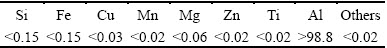
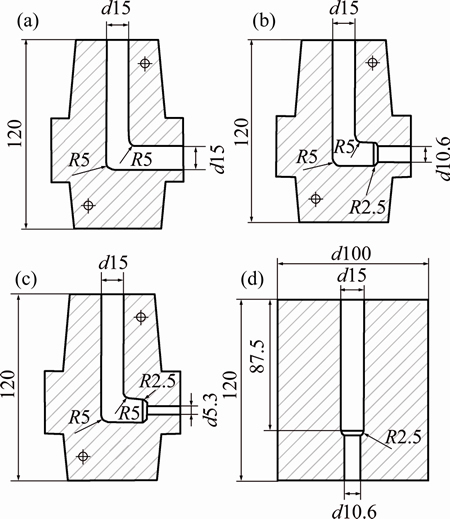
Fig. 1 Drawing of ECAP (a), ECAPEX2 (b), ECAPEX8 (c) and EX2 dies (d) (unit: mm)
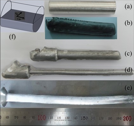
Fig. 2 Macrographs of as-cast Al-1080 machined (a), deformed by ECAP (b), ECAPEX2 (c) and ECAPEX8 (d), EX2 workpieces (e) and transverse (TD) and longitudinal (LD) direction (f)
The workpieces after different deformation processes were cut in the transverse direction as shown in Fig. 2(f). The workpieces were carefully ground and polished to a mirror-like surface. Hardness measure- ments were carried out using a Mitutoyo microhardness tester equipped with a Vickers indenter under an applied load of 980 N and dwell time of 15 s. The microhardness measurements were taken in the form of a regular grid pattern with a spacing of 0.5 mm between each point [12]. Then, the microhardness measurements were plotted as color-coded contour maps indicating the variation in the microhardness across the surface of each workpiece. A total number of 701, 317, 81 and 317 measurements were made in the case of the ECAP, the combination of ECAP + extrusion with extrusion ratios of 2 and 8 and extrusion workpieces, respectively. The average of the microhardness measurements in each case was denoted as the average microhardness. The standard deviation (��Hv) of the microhardness measurements in each case was calculated to assess the deformation inhomogeneity index of the different workpieces from the following equation [12]:
 (3)
(3)
where Hi, Hav and NHv are the microhardness value at each point of measurement, the average microhardness of the whole measurements and the total number of measurements, respectively. In the present work, the measured microhardness values were compared with microhardness values calculated based on the effective plastic strain through mathematical calculations. As the microhardness values were estimated using the effective plastic strain values. Moreover, a complete comparison between the strain and microhardness distribution maps was performed.
Microstructure observations after the deformation processes were performed in both longitudinal and transverse directions as shown in Fig. 2(f). The microstructure observations in the longitudinal direction were performed by optical microscope to trace the shear bands morphology and width in different deformation processes. Further microstructure observations were performed in the transverse direction by scanning electron microscopy (SEM) with electron backscatter diffraction (EBSD). The EBSD observations were concerned with the tracing of the grain size variation along the workpieces diameter. The microstructure observations in the both longitudinal and transverse directions were performed in different positions across each workpiece. The microstructure observations were undertaken at the bottom and the top of ECAP workpiece and at the center and the outer surface of the combination of ECAP + extrusion and extrusion workpieces, respectively.
The microstructure workpieces were prepared by grinding using up to 4000 SiC emery papers, followed by polishing with alcohol and diamond paste suspensions to mirror-like surfaces. Then, the workpieces were etched using Keller��s reagent in the case of the optical microscope workpieces. The workpieces were polished by colloidal silica and ethanol for 1 h to obtain a very shiny polished surface in the case of the EBSD workpieces. Step sizes with values between 60 and 40 nm were used in the EBSD mapping process. Moreover, the points with confidence index (CI)��0.1 were removed for using more reliable data. In order to avoid any confusion, the workpieces were termed as ECAP, ECAPEX2, ECAPEX8, and EX2 in the case of the equal channel angular pressing, the combination of ECAP + extrusion with extrusion ratios of 2 and 8 and the direct extrusion with an extrusion ratio of 2, respectively.
4 Results and discussion
4.1 Load-displacement curves
Figure 3(a) shows the FEM and experimental load-displacement curves. In the case of ECAP, the load was increased as the workpiece entered the deformation zone (the intersection between the entrance and exit channels), with a ramp, which was followed by a steady load with a slight decrease in the load value with the increase of the displacement. The load was increased up to 36.2 kN and remained approximately constant, then it slightly decreased with the further pressing down to 31.5 kN. Similar load behavior was noted in the case of experimental ECAP load-displacement curve. The load increases up to 34.7 kN and remains constant with a slight decrease in the load value with the further pressing down to 30.9 kN. The FEM and experimental load-displacement curves were observed to be very close each other, which proves the efficiency of the FEM simulation in the prediction of load�Cdisplacement curve behavior with high accuracy. Similar ECAP load-displacement behavior was noted in the ECAP of Al-1070 [32].
The ECAP experimental and FEM load- displacement curves in the present work have a ramp followed by a steady load shape. The load-displacement curves in the present work were free from the bend and shear stages with higher peak load than those noted in previous works [22,32,33]. The difference in the load- displacement curve behavior in the present and previous works can be explained by the difference in the outer die angle (��) values. A critical value of �� of 40�� was the factor that affects the shape and the peak load value of the load-displacement curve of ECAP [32]. As in the case of ����40�� (for example ��=15�� in the present work), a high peak load with a ramp followed by a steady state area load-displacement curve was noted. On the other hand, in the case of ����40 bend and shear stages followed by a steady state area load-displacement curve with a low peak load was noted [22,32,33].
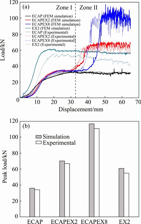
Fig. 3 FEM simulations and experimental load-displacement curves (a) and peak load of Al-1080 deformed by ECAP, ECAPEX2, ECAPEX8, and EX2 (b)
The FEM load-displacement curves in the case of ECAPEX2 and ECAPEX8 can be distinguished into two zones as shown in Fig. 3(a). Zone �� as the workpiece undergoes the ECAP process, where the load was at the same level as that noted in the individual ECAP process. After the workpiece enters the extrusion zone �� the load increases suddenly. The load was increased from approximately 34.8 kN to 69 and 113 kN in the case of ECAPEX2 and ECAPEX8, respectively. This increase in the load in the extrusion step after the ECAP can be explained by the reduction in the cross-section area of the workpiece and the effect of the back pressure [22]. The experimental load-displacement curves in the case of ECAPEX2 and ECAPEX8 have similar trends with close values to those of the FEM. The load was increased from 34 kN up to 65 and 110 kN in the case of experimental ECAPEX2 and ECAPEX8 curves, respectively, as shown in Fig. 3(a). The load was increased by 64% and 69% by increasing the extrusion ratio from 2 to 8 in the case of the FEM and experimental curves, respectively. The increase of the load can be interpreted by the high degree of deformation needed for a further reduction in the workpiece cross- section area. The load value in extrusion step zone �� in FEM and experimental load-displacement curves had oscillated with a larger range than that in the ECAP process. The appearance of large oscillations can be explicated by the inhomogeneous deformation during the extrusion process.
The load-displacement curve behavior in the case of the extrusion process was similar to that of the ECAP process. The load increases up to 61.7 kN as the workpiece enters the deformation zone, then it slight decreases with the further pressing down to 55.4 kN. The higher load that noted in the extrusion can be explained by the reduction in the cross-section area during the extrusion process. The extrusion FEM and experimental load-displacement curves in the present work were congruent with those obtained by FEM and experimental validation of the cold extrusion of different aluminum alloys using different dies and lubrications [34-36].
Figure 3 (b) shows the FEM and the experimental peak load values of different forming processes. The peak loads of 36.3, 70.3, 117.2 and 61.2 kN were noted in the case of the FEM of ECAP, ECAPEX2, ECAPEX8, and EX2, respectively. The peak load values were 34.7, 67.2, 110.7 and 55 kN in the case of the experimental results of ECAP, ECAPEX2, ECAPEX8, and EX2, respectively. The high peak load in the case of ECAPEX2 and ECAPEX8 can be interpreted by the higher degree of deformation in those processes. Moreover, the effect of the back pressure occurred during the both processes. The FEM and experimental peak load values for different forming processes were near from each other with error ranges from 1.6 to 6.5 kN. The present results indicate the efficiency of the 3D FEM in the prediction of the load-displacement curves and peak load values in different deformation processes with good agreement with the experimental results.
4.2 Effective plastic strain distribution
Figure 4 shows the FEM effective plastic strain distribution maps of ECAP, ECAPEX2, ECAPEX8 and EX2 in the transverse direction. In the case of ECAP, the effective plastic strain values were higher at the top than that at the bottom of the workpiece. The effective plastic strain was increased from 0.8 at the bottom to 1.6 at the top as shown in Fig. 4(a). About 75% of the workpiece area has an effective plastic strain value near 1.08 which was observed to be equal to that calculated for one pass by IWAHASHI et al [2]. Similar strain distribution patterns were noted in the 3D FEM of ECAP [17-20]. The increase of the effective plastic strain from the bottom to the top can be explained by the formation of the corner gap [21]. As the bottom part of the workpiece is no longer in contact with the die. Consequently, lower degree of deformation occurred in the bottom of the workpiece [21].

Fig. 4 Effective plastic strain distribution contours through workpiece transverse direction (cross-section) of Al-1080 deformed by ECAP (a), ECAPEX2 (b), ECAPEX8 (c) and EX2 (d)
In the case of the ECAPEX2, the effective plastic strain was increased from the center toward the outer surface of the workpiece as shown in Fig. 4(b). The effective plastic strain was increased from 1.7 at the center up to 2.5 at the outer surface of the workpiece. Similar strain distribution patterns were also observed in the case of the ECAPEX8 and EX2 as shown in Figs. 4(c) and (d), respectively. The effective plastic strain differences between the center and the outer surfaces were 0.8, 0.88 and 0.93 in the case of ECAPEX2, ECAPEX8, and EX2, respectively. This variation in the effective plastic strain from the workpiece center to the outer surface can explain by the higher friction and so higher strain hardening at the workpiece outer surface. Similar effective plastic strain distribution patterns were observed in the FEM of the combination of ECAP + extrusion, extrusion, and equal channel forward extrusion (ECFE) [22,34-38]. Interestingly, it can be noted that the FEM average effective plastic strain values were close to those calculated from the theoretical equations [2,31] as shown in Fig. 5. The deviations between the FEM and calculated effective plastic strain values were 1%, 5.6%, 4% and 20% in the case of the ECAP, ECAPEX2, ECAPEX8, and EX2, respectively. So, it can be observed that the 3D FEM can be used efficiently in the prediction of the average effective plastic strain value in the present study.
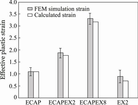
Fig. 5 Average FEM simulation and calculated effective plastic strains with standard deviation of Al-1080 deformed by ECAP, ECAPEX2, ECAPEX8 and EX2 (Error bar indicates inhomogeneity index)
The effective plastic strain distribution in the transverse direction was further confirmed through the tracing of the effective plastic strain distribution along the longitudinal direction as shown in Fig. 6. The effective plastic strain distribution patterns in the longitudinal direction were in a good agreement with those of the transverse one. The effective plastic strain was increased from the bottom to the top in the case of ECAP and from the center to the outer surface in the case of ECAPEX2, and EX2 as shown in Fig. 6. A reasonable steady state deformation region was formed in the different deformation processes, as shown in Figs. 4 and 6. The steady state deformation region can be defined by an approximately constant effective plastic strain region in each case. The steady state deformation region occupied about 75%, 35%, 47% and 26% of the area in the case of ECAP, ECAPEX2, ECAPEX8, and EX2 workpieces respectively, as shown in Figs. 4 and 6. Interestingly, the ratio of the steady state region length to the workpiece width (diameter) in the ECAP was 2.5:1, which was observed to be sufficient as previously noted [22,30,32,39]. This gives a good indication of the efficiency of the FEM simulation results in the present work.
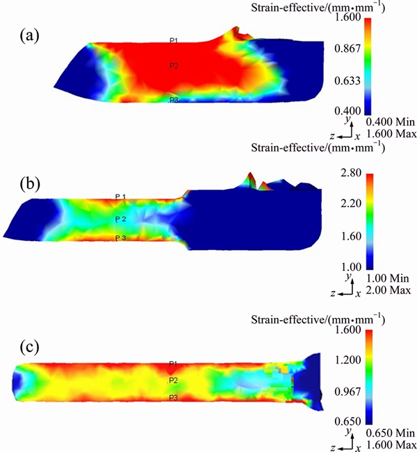
Fig. 6 Effective plastic strain distribution contours in longitudinal direction (pressing direction) of Al-1080 deformed by ECAP (a), ECAPEX2 (b) and EX2 (c)
The effective plastic strain distributions in the longitudinal direction of the ECAPEX2, ECAPEX8 and EX2 have approximately axisymmetric distributions patterns as previously noted [22,25]. The deviation of the effective plastic strain distribution patterns from the ideal axisymmetric one can be explicated by the high coefficient of friction of 0.12. This coefficient of friction was obviously higher than 0.05-0.07 used in the cold extrusion process modeled as axisymmetric [34,40]. It must take consideration that the coefficient of friction applied in the present was more practical than that used in cold extrusion modeled as axisymmetric [34,40]. The coefficient of friction applied in the present work was near to that recommended in the cold forming of aluminum [28]. So, the present results are more accurate and representative for the real effective plastic strain distributions in the case of the ECAP, the combination of the ECAP + extrusion and extrusion processes.
The effective plastic strain distributions in the transverse and longitudinal directions were confirmed through the tracing of the effective plastic strain variation at three points along the workpiece diameter as shown in Fig. 7. The effective plastic strain variation was traced at points 1 and 3 at the outer surface and point 2 at the center of the workpieces as shown in Fig. 6. Point 3 at the bottom of the ECAP workpiece has higher strain than points 1 and 2 after entering the shear zone (the intersection of the ECAP channels) as shown in Fig. 7(a). The higher strain at point 3 can be explained as it is the first point to be pressed and deformed before points 1 and 2. Through further pressing and with the formation of the corner gap at the workpiece bottom [21], the strain distribution was changed. The effective plastic strain was increased gradually from point 3 at the bottom up to point 1 at the top similar to that noted in Figs. 4(a) and 6(a). The difference between the effective plastic strain values at points 1 and 3 was 0.67 which was close to that noted in the transverse direction as shown in Fig. 4(a). In the case of ECAPEX2 and EX2, the tracing of the effective plastic strain variation indicates higher strain at the outer surface than that at the center. In the case of the ECAPEX2, the effective plastic strain behavior in the ECAP step was similar to that noted in the initial stage of the ECAP process as shown in Figs. 7(a) and (b). After the workpiece entered into the extrusion region the effective plastic strain distribution pattern changed. The effective plastic strain values were approximately equal at the outer surface at points 1 and 3, with higher strain than that at point 2. The effective plastic strain difference between the outer surface at points 1 and 3 and at the center point 2 was 0.73. This value was close to the effective plastic strain difference between the outer surface and center noted in the transverse direction of 0.8 as shown in Fig. 4(b).
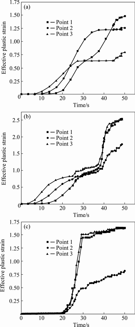
Fig. 7 Effective plastic strain variation tracing through points 1, 2 and 3 (indicated in Fig. 7) of Al-1080 deformed by ECAP (a), ECAPEX2 (b) and EX2 (c)
Although the EX2 workpiece has similar effective plastic strain distribution pattern as that noted in the case of the ECAPEX2. But it was observed that the strain was increased from the center to the outer surface with a higher rate than that noted in the case of the ECAPEX2 as shown in Fig. 7(c). The difference between the effective plastic strain values at outer surface points 1 and 3 and at the center point 2 was 0.87, which was higher than that in the case of ECAPEX2. Similar observation of the strain difference between the workpiece outer surface and center through the three points tracing was noted during FEM simulation of the combination of extrusion + ECAP and extrusion of magnesium alloy [25]. The effective plastic strain variations at three points shown in Figs. 7(b)-(c) support the results that the effective plastic strain distribution patterns in the case of the ECAPEX2 and EX2 are approximately axisymmetric distribution patterns as shown in Figs. 4(b) and (c), and Figs. 6(b) and (c). Interestingly, it was noted that the extrusion step that follows the ECAP step in the ECAPEX2 and ECAPEX8 can be considered the predominated operation that has higher effects on the effective plastic strain distribution pattern shape in the case of the combination of ECAP + extrusion process.
The inhomogeneity indices of the effective plastic strain calculated from Eq. (2) are shown as error bars in Fig. 5. The deformation homogeneity was higher in the case of the ECAP than that in the other deformation processes. The inhomogeneity indices were increased from 0.17 in the case of the ECAP up to 0.2, 0.23 and 0.28 in the case of ECAPEX2, ECAPEX8, and EX2, respectively. So, it can be observed that the ECAP has a higher degree of deformation homogeneity than the other deformation processes. This can be interpreted by the free flow in the case of the ECAP compared with the reduction in the cross-section area in ECAPEX2, ECAPEX8, and EX2. Furthermore, the higher friction in ECAP + extrusion and extrusion leads to a higher degree of strain hardening at the workpiece outer surface than that at its center, which increases the effective plastic strain difference between the outer surface and center and so decreases deformation homogeneity. Similar observations were noted through the FEM simulations of Al [22,34-37]. The effective plastic strain inhomogeneity indices in the case of ECAPEX2 and ECAPEX8 were lower than that in the case of EX2. This can be explained by the higher degree of deformation in the case of ECAPEX2 and ECAPEX8. The FEM results were verified by the microhardness measurements and microstructure observations.
4.3 Microhardness results
Figure 8 shows the microhardness distribution color-coded maps of Al-1080 processed by ECAP, ECAPEX2, ECAPEX8 and EX2 in the transverse direction. In the case of the as-cast Al-1080 workpiece, the microhardness distribution was observed to be homogeneous with average microhardness and micro- hardness inhomogeneity index of HV 27.3��0.05 and HV 1.1, respectively [10]. The microhardness distribution becomes less homogeneous after the ECAP process as shown in Fig. 8(a). The microhardness increased gradually from bottom to top with a lower microhardness area at the bottom of the workpiece [3,21,41]. The lower microhardness area at the bottom of the workpiece can be explained by the formation of corner gap [3,21]. The difference between the microhardness values at the top and the bottom was HV 5.4 as shown in Fig. 8(a). The average microhardness and microhardness inhomogeneity index in the case of ECAP were HV 39.7��0.3 and HV 1.7, respectively, as shown in Fig. 9. A close agreement between the effective plastic strain and microhardness distribution was noted as shown in Figs. 4(a) and 8(a). The high microhardness area at the top of the workpiece is corresponding to the high effective plastic strain area and the low microhardness area at the bottom is corresponding to the low effective plastic strain area.
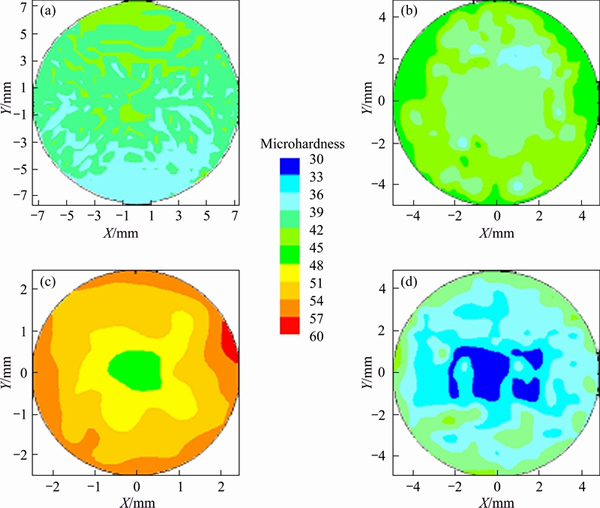
Fig. 8 Color-coded hardness contour map showing microhardness distribution in workpiece cross-section of Al-1080 deformed by ECAP (a), ECAPEX2 (b), ECAPEX8 (c) and EX2 (d)
Microhardness distribution patterns of ECAPEX2, ECAPEX8, and EX2 have similar features as shown in Figs. 8(b)-(d). The microhardness gradually increased from the workpiece center to outer surface. The microhardness values were increased from HV 42.1, HV 46.5 and HV 30.8 at the center up to HV 48.9, HV 56.5 and HV 42 at the outer surface in the case of the ECAPEX2, ECAPEX8, and EX2, respectively. The microhardness differences between the center and the outer surface were HV 6.8, HV 10 and HV 11.8 in the case of ECAPEX2, ECAPEX8, and EEX2, respectively. Similar microhardness distribution patterns with close microhardness difference between the workpieces center and the outer surface were noted in the case of the cold extrusion of Al-1100 using different extrusion die angles and lubrications [35]. The higher values of the microhardness at the outer surface in the case of ECAPEX2, ECAPEX8, and EX2 can be explicated by the higher friction and so strain hardening at the outer surface. The effective plastic strain and microhardness distributions in the case of ECAPEX2, ECAPEX8, and EX2 were in good agreement with each other, as shown in Figs. 4(c), (d) and Figs. 8(c), (d). The microhardness distribution maps of the different deformation processes confirm the efficiency of the FEM in achieving accurate effective plastic strain distribution maps. Moreover, the effective plastic strain and microhardness difference between the center and outer surface have the same trend.
The average microhardness values were HV (45.8��0.3), HV (52.4��0.4) and HV (36.9��0.7) in the case of ECAPEX2, ECAPEX8, and EX2, respectively as shown in Fig. 9. The average microhardness values of the ECAPEX2 and ECAPEX8 were higher than that of the ECAP due to the higher imposed effective plastic strain and so the further grain refinement will be indicated in the microstructure section. The microhardness inhomogeneity indexes in the case of ECAPEX2, ECAPEX8, and EX2 were HV 2.2, HV 2.6 and HV 3.3, respectively as shown in Fig. 9. The inhomogeneity indexes extracted from the effective plastic strain and microhardness results have the same trend as indicated in Figs. 5 and 9. The microhardness inhomogeneity indexes results confirm effective plastic strain inhomogeneity indexes results of which the ECAP workpiece has a higher degree of deformation homogeneity than the other deformation processes. The ECAPEX2 and ECAPEX8 processes have a higher degree of deformation homogeneity than that of EX2. This observation supports the congruence between the FEM and experimental results.
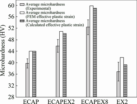
Fig. 9 Average experimental microhardness with standard deviations and average calculated microhardness (from FEM and calculated average effective plastic strains) of Al-1080 deformed by ECAP, ECAPEX2, ECAPEX8 and EX2 (Error bar indicates inhomogeneity index)
Further, correlation between the effective plastic strain and the microhardness were performed in the present study. The Vickers microhardness values were calculated based on the average effective plastic strain values using the following equation [42]:
HV=cK(��e+��0)n (4)
where HV, c, K, ��e, ��0 and n are Vickers microhardness, constraint factor [43], strength coefficient, representative strain, effective equivalent strain and strain hardening exponent, respectively. The material parameters K and n were obtained from the stress-strain relation of Al-1080 [10]. The calculations of the representative strain were explained in the previous work [43]. The representative strain value obtained in the present work was 0.15, which was observed to be close or even equal to those noted in the previous works [43, 44]. The equivalent effective strain values used in the present work are calculated and FEM average effective plastic strain values in the case of the ECAP, ECAPEX2, ECAPEX8, and EX2 are indicated in Fig. 5. The constraint factor c was calculated through the following equation [42]:
c=HVi/��e (5)
where HVi and ��e [42] are Vickers microhardness of initial condition and the representative stress of the material was obtained from the following equation [42]:
 (6)
(6)
The constraint c factor value used in the present work was 3, which was near from those noted in previous works [42,43]. The experimental and calculated average microhardness values were close from each other as shown in Fig. 9. The differences between the experimental and calculated average microhardness (based on FEM and calculated strain values) were in the ranges of 2.4-4.9, 4.3-4.2, 5.1-4.4, and 7.4-6.7 in the case of EX2, ECAP, ECAPEX2, and ECAPEX8, respectively. The present and previous observations [42] indicated that the difference between the measured and predicted microhardness values has not a defined trend with the imposed strain. It is noted that the difference between the experimental and calculated average microhardness in the present work was smaller than those noted in the previous work [42]. These results prove that the FEM and calculated effective plastic strain values were accurately obtained in the present work. The deviation of the experimental microhardness values from those obtained from Eq. (4) was much smaller than that noted by TABOR [45]. So, the FEM and calculated effective plastic strains can be used effectively in the prediction of the microhardness of the deformed material using Eq. (4) with a reasonable level of accuracy.
4.4 Microstructure observations
Figure 10 shows the optical microscope micrograph of the shear bands (shear streams) in the longitudinal direction (pressing direction) in the case of ECAP. It was noted that the average width of shear bands was decreased from 53.3 ��m at the bottom as shown in Fig. 10(a) down to 39.9 ��m at the top as shown in Fig. 10(b). The decrease in the width of shear band from the bottom to top will relate to the increase of the effective plastic strain from the bottom to top as shown in Fig. 6(a). A similar decrease in the width of shear band from the bottom to the top of the ECAP workpiece was noted through the FEM and the microstructure observations of the ECAP of Cu [17].
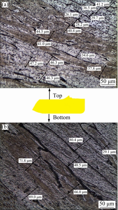
Fig. 10 OM micrograph of shear band in longitudinal direction (pressing direction) corresponding Al-1080 deformed by ECAP at top (a) and bottom (b)
The microstructure observations noted by the optical microscope shown in Fig. 10 were further confirmed through the tracing of the grain size variation from the workpiece bottom to top by using the EBSD in the transverse direction. Figure 11 shows the EBSD color-coded orientation maps of the Al-1080 workpiece processed by ECAP. The grain colors correspond to the orientations in the unit triangle, as shown in Fig. 11. The microstructure at the bottom and the top of the workpiece consists of elongated grains. The average grain was decreased from 25.5 at the bottom to 20 ��m at the top, as shown in Figs. 11(a) and (b). The microstructure observations were in a good agreement with the decrease of the shear band width from the bottom to the top. Moreover, these observations confirm the increase of the microhardness from the bottom to top as shown in Fig. 8(a). The decrease of the grain size and the increase of the microhardness from the bottom to the top of the workpiece can be interpreted by the increase of the effective plastic strain from bottom to top as shown in Fig. 4(a), which can be related to the formation of the corner gap. The present results are in agreement with those noted in the case of Cu and Al 1050 processed by ECAP up to one pass [27,46].
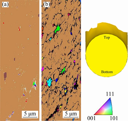
Fig. 11 Color-coded orientation map images of Al-1080 deformed by ECAP at bottom (a) and top (b) of sample
The microstructure observations in the longitudinal direction of the ECAPEX2 and ECAPEX8 workpieces indicated a change in the shear band width from the center to the outer surface of the workpiece as shown in Figs. 12 and 13, respectively. The average width of shear bands was decreased from 40.7 and 34 ��m at center down to 33.9 and 24 ��m at the outer surface in the case of the ECAPEX2 and ECAPEX8, respectively. Similar behavior of the decrease of the shear band width from the workpiece center to the surface was also noted in the case of the EX2 workpiece as shown in Fig. 14. The average width of shear bands decreases from 69.9 ��m at the center down to 53 ��m at the outer surface in the case of EX2. The decrease of the shear band width from the workpiece center to the outer surface can be related to the increase of the effective plastic strain from the center to the outer surface as shown in Fig. 6. As a lower effective plastic strain area at the center corresponded to wider shear band than that at the outer surface corresponding to a higher effective plastic strain area. Moreover, the high strain hardening due to high friction at the outer surface contributes to the formation of thinner shear bands at the outer surface than that at the center.
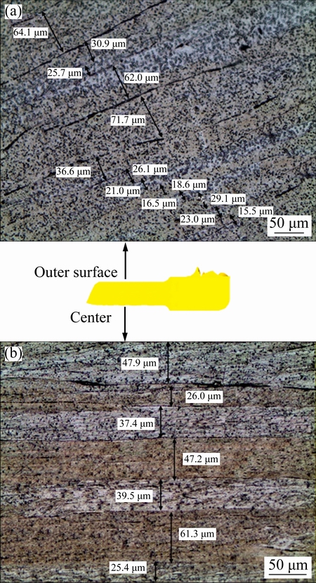
Fig. 12 OM micrograph of Al-1080 deformed by ECAPEX2 in longitudinal direction (pressing direction) at outer surface (a) and center (b)
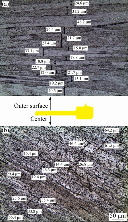
Fig. 13 OM micrograph of Al-1080 deformed by ECAPEX8 in longitudinal direction (pressing direction) at outer surface (a) and center (b)
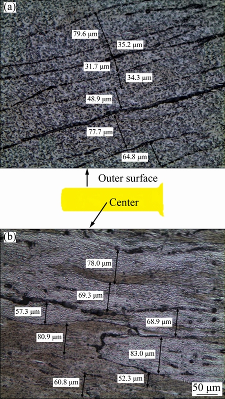
Fig. 14 OM micrograph of Al-1080 deformed by EX2 in longitudinal direction (pressing direction) at outer surface (a) and center (b)
Further observations of the grain size variation from the center to the outer surface in the case of ECAPEX2, ECAPEX8 and EX2 were performed by EBSD as shown in Figs. 15-17, respectively. In the case of ECAPEX2 and ECAPEX8, the microstructure at the center consists of a mixture of big and small irregular grains with average grain sizes of 26.5 and 20.5 ��m as shown in Figs. 15(a) and 16(a), respectively. At the outer surface, the microstructure consisted of a combination of elongated, equiaxed and irregular grains with average grain sizes of 4.9 and 2.5 ��m as shown in Figs. 15(b) and 16(b), respectively. The EX2 workpiece has similar microstructure features of the decrease of the average grain size from the center toward the outer surface as noted in the case of ECAPEX2 and ECAPEX8 as shown in Fig. 17. The average grain size after EX2 was varied from 65 to 33.4 ��m at the center and the outer surface, respectively. The decrease of the average grain size from the center to the outer surface in the case of ECAPEX2, ECAPEX8 and EX2 can be explained by the increase of the effective plastic strain from center to outer surface as shown in Figs. 4(b)-(d). This is also in good agreement with the microhardness distribution as shown in Figs. 8(b)-(d). The grain size in the case of EX workpiece was larger than those in the case of ECAPEX2 and ECAPEX8 due to the high degree of deformation in the case of ECAPEX2 and ECAPEX8, which leads to further grain refinement. Similar, the decrease in the shear band width and the grain size from the center to the outer surface was noted in the case of 6xxx-series aluminum alloys extruded under different temperatures and extrusion ratios [47].
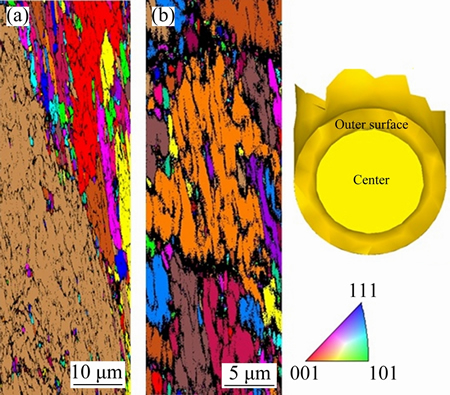
Fig. 15 Color-coded orientation map images of Al-1080 deformed by ECAPEX2 at center (a) and outer surface (b)
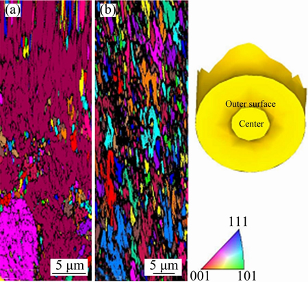
Fig. 16 Color-coded orientation map images of Al-1080 deformed by ECAPEX8 at center (a) and outer surface (b)
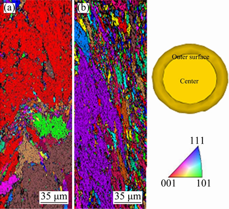
Fig. 17 Color-coded orientation map images of Al-1080 deformed by EX2 at center (a) and outer surface (b)
5 Conclusions
1) FEM effectively predicts the load-displacement behavior for ECAP, the combination of ECAP + extrusion and direct extrusion processes. The load-displacement curves of the FEM and experimental results are in good agreement. The load-displacement curves shape, stages, and behavior were explicated in the case of different deformation processes. The FEM provided accurate and close peak load values to those observed by experimental work.
2) The 3D FEM simulation can be successfully used to investigate the distribution of effective plastic strain across the transverse and longitudinal directions of Al workpieces deformed by different processes. The effective plastic strain distribution depends on the deformation process. The effective plastic strain was increased from the bottom to the top in the case of the ECAP, and from the center to the outer surface in the case of the combination of ECAP + extrusion and direct extrusion. The FEM average effective plastic strain values were accurately obtained and were close to the calculated values with error ranges from 1% to 20%.
3) The microhardness distribution maps are in a good conformity with the effective plastic strain distribution maps, which verifies the 3D FEM simulations results. The effective plastic strain and microhardness deformation inhomogeneity indexes have the same trend. The FEM and experimental results indicate that the ECAP workpiece has a higher degree of deformation homogeneity than the other deformed workpieces.
4) The microhardness values were efficiently predicted using the average FEM and calculated effective plastic strain values and the results fit the experimental measurements well. The estimated values were close to the experimental microhardness values with error range from HV 2.4 to HV 7.4.
5) The microstructure observations in the longitudinal and transverse directions support the effective plastic strain and microhardness distribution maps and verify the FEM results.
References
[1] VALIEV R Z, LANGDON T G. Principles of equal-channel angular pressing as a processing tool for grain refinement [J]. Progress in Materials Science, 2006, 51: 881-981.
[2] IWAHASHI Y, WANG J, HORITA Z, NEMOTO M, LANGDON T G. Principle of equal-channel angular pressing for the processing of ultra-fine grained materials [J]. ScriptaMaterialia, 1996, 35: 143-146.
[3] El MAHALLAWY N, SHEHATA F A, El HAMEED M A, El AAL M I A. Effect of Cu content and number of passes on evolution of microstructure and mechanical properties of ECAPed Al/Cu alloys [J]. Materials Science and Engineering A, 2009, 517: 46-50.
[4] El-DANAF E A. Mechanical properties and microstructure evolution of 1050 aluminum severely deformed by ECAP to 16 passes [J]. Materials Science and Engineering A, 2008, 487: 189-200.
[5] EL AAL M I A, El MAHALLAWY N, SHEHATA F A, El HAMEED M A, YOON E Y, LEE J H, KIM H S. Tensile properties and fracture characteristics of ECAP-processed Al and Al-Cu alloys [J]. Metals and Materials International, 2010, 16: 709-716.
[6] STOLYAROV V V, ZHU Y T, LOWE T C, VALIEV R Z. Microstructure and properties of pure Ti processed by ECAP and cold extrusion [J]. Materials Science and Engineering A, 2005, 303: 82-89.
[7] NAGARAJAN D, CHAKKINGAL U, VENUGOPAL P. Influence of cold extrusion on the microstructure and mechanical properties of an aluminium alloy previously subjected to equal channel angular pressing [J]. Journal of Materials Processing Technology, 2007, 182: 363-368.
[8] NAIZABEKOV A B, ANDREYACHSHENKO V A, KOCICH R. Study of deformation behavior, structure and mechanical properties of the AlSiMnFe alloy during ECAP-PBP [J]. Micron, 2013, 44: 210-217.
[9] YING Tao, HUANG Jian-ping, ZHENG Ming-yi. Influence of secondary extrusion on microstructures and mechanical properties of ZK60 Mg alloy processed by extrusion and ECAP [J]. Transactions of Nonferrous Metals Society of China, 2012, 22: 1896-1901.
[10] EL AAL M I A, UM H Y, YOON E Y, KIM H S. Microstructure evolution and mechanical properties of pure aluminum deformed by equal channel angular pressing and direct extrusion in one step through an integrated die [J]. Materials Science and Engineering A, 2015, 625: 189-200.
[11] LUGO N, LLORCA N, CABRERA J M, HORITA Z. Microstructures and mechanical properties of pure copper deformed severely by equal-channel angular pressing and high pressure torsion [J]. Materials Science and Engineering A, 2008, 477: 366-371.
[12] EL AAL M I A, YOON E Y, KIM H S. Microstructure evolution and mechanical Properties of Al-1080 processed by a combination of equal channel angular pressing and high pressure torsion [J]. Metallurgical and Materials Transactions A, 2013, 44: 2581-2590.
[13] KIM H S, SEO M H, HONG S I. Plastic deformation analysis of metals during equal channel angular pressing [J]. Journal of Materials Processing Technology, 2001, 113: 622-626.
[14] PEREZ C J L. On the correct selection of the channel die in ECAP processes [J]. ScriptaMaterialia, 2004, 50: 387-393.
[15] YOON S C, QUANG P, HONG S I, KIM H S. Die design for homogeneous plastic deformation during equal channel angular pressing [J]. Journal of Materials Processing Technology, 2007, 187-188: 46-50.
[16] KIM H S, SEO M H, HONG S I. On the die corner gap formation in equal channel angular pressing [J]. Materials Science and Engineering A, 2000, 291: 86-90.
[17] SUO Tao, LI Yu-long, GUO Ya-zhou, LIU Yuan-yong. The simulation of deformation distribution during ECAP using 3D finite element method [J]. Materials Science and Engineering A, 2006, 432: 269-274.
[18] BASAVARAJ V P, CHAKKINGAL U, KUMAR T S P. Study of channel angle influence on material flow and strain inhomogeneity in equal channel angular pressing using 3D finite element simulation [J]. Journal of Materials Processing Technology, 2009, 209: 89-95.
[19] XU Shu-bo, ZHAO Guo-qun, LUAN Yi-guo, GUAN Yan-jin. Numerical studies on processing routes and deformation mechanism of multi-pass equal channel angular pressing processes [J]. Journal of Materials Processing Technology, 2006, 176: 251-259.
[20] JIANG Hong, FAN Zhi-guo, XIE Chao-ying. 3D finite element simulation of deformation behavior of CP-Ti and working load during multi-pass equal channel angular extrusion [J]. Materials Science and Engineering A, 2008, 485: 409-414.
[21] El MAHALLAWY N, SHEHATA F A, El HAMEED M A, El AAL M I A, KIM H S. 3D FEM simulations for the homogeneity of plastic deformation in Al-Cu alloys during ECAP [J]. Materials Science and Engineering A, 2010, 527: 1404-1410.
[22] NAGASEKHAR A V, YOON S C, YOO J H, KANG S Y, BAIK S C, El AAL M I A, KIM H S. Plastic flow and strain homogeneity of an equal channel angular pressing process enhanced through forward extrusion [J]. Materials Transactions, 2010, 51: 977-981.
[23] PUERTAS I, PEREZ C J L, SALCEDO D, LEON J, FUERTES J P, LURI R. Design and mechanical property analysis of AA1050 turbine blades manufactured by equal channel angular extrusion and isothermal forging [J]. Materials & Design, 2013, 52: 774-784.
[24] KOCICH R, KUNCICKA L, MIHOLA M, SKOTNICOVA K. Numerical and experimental analysis of twist channel angular pressing (TCAP) as a SPD process [J]. Materials Science and Engineering A, 2013, 563: 86-94.
[25] HU H J, WANG H, ZHAI Z Y, LI Y Y, FAN J Z, ZHONGWEN O U. The influences of shear deformation on the evolutions of the extrusion shear for magnesium alloy [J]. The International Journal of Advanced Manufacturing Technology, 2014, 74: 423-432.
[26] DEFORM TM 3D Version.6.1. User��s manual scientific forming technologies corporation [M]. Columbus, Ohio, 43220.
[27] XU S, ZHAO G, REN G, MA X. Numerical simulation and experimental investigation of pure copper deformation behavior for equal channel angular pressing/extrusion process [J]. Computational Materials Science, 2008, 44: 247-252.
[28] ESMAILZADEH M, KHAFRI M A. Finite element and artificial neural network analysis of ECAP [J]. Computational Materials Science, 2012, 63: 127-133.
[29] HENSEL A, POLUCHIN P I, POLUCHIN W P. Technologie der Metallformung: Eisen- und Nichteisenmetalle [M]. Weinheim, German: Wiley-VCH, 1991.
[30] LI S, BOURKE MAM, BEYERLEIN I J, ALEXANDER D J, ClAUSEN B. Finite element analysis of the plastic deformation zone and working load in equal channel angular extrusion [J]. Materials Science and Engineering A, 2004, 382: 217-236.
[31] GROOVER M P. Fundamentals of modern manufacturing: materials, processes, and systems [M]. 3rd ed.New York: John Wiley & Sons,Inc, 2007.
[32] BALASUNDAR I, RAO M S, RAGHU T. Equal channel angular pressing die to extrude a variety of material [J]. Materials & Design, 2009, 30:1050-1059.
[33] KIM H S. Finite element analysis of equal channel angular pressing using around corner die [J]. Materials Science and Engineering A, 2001, 315: 122-128.
[34] MERKLEIN M, NDZOMSSI F, ENGEL U. Investigation of the influence of tool geometry on effective strain distribution in full forward extrusion [C]//AIP Conference Proceedings. Belfast, United Kingdom, 2011, 1353: 419-424.
[35] CHAUDHARI G A, ANDHALE S R, PATIL N G. Experimental evaluation of effect of die angle on hardness and surface finish of cold forward extrusion of aluminum [J]. International Journal of Emerging Technology and Advanced Engineering, 2012, 2: 334-338.
[36] CHEN D C, SYU S K, WU CH, LIN S K. Investigation into cold extrusion of aluminum billets using three-dimensional finite element method [J]. Journal of Materials Processing Technology, 2007, 192-193: 188-193.
[37] KARAYEL D. Simulation of direct extrusion process and optimal design of technological parameters using FEM and artificial neural network [J]. Key Engineering Materials, 2008, 367: 185-192.
[38] EBRAHIMI M, DJAVANROODI F. Experimental and numerical analyses of pure copper during ECFE process as a novel severe plastic deformation method [J]. Progress in Natural Science, 2014, 24: 68-74.
[39] LI S. Application of crystal plasticity modeling in equal channel angular extrusion [J]. Transactions of Nonferrous Metals Society of China, 2013, 23: 170-179.
[40] PETRUSKA J,  L. On the evaluation of strain inhomogeneity by hardness measurement of formed products [J]. Journal of Materials Processing Technology, 2003, 143-144: 300-305.
[41] XU C, FURUKAWA M, HORITA Z, LANGDON T G. The evolution of homogeneity and grain refinement during equal-channel angular pressing: A model for grain refinement in ECAP [J]. Materials Science and Engineering A, 2005, 398: 66-76.
[42] SONMEZ F O, DEMIR A. Analytical relations between hardness and strain for cold formed parts [J]. Journal of Materials Processing Technology, 2007, 186: 163-173.
[43] TEKKAYA A E, LANGE K. An improved relationship between vickers hardness and yield stress for cold formed materials and its experimental verification [J]. CIRP Annals-Manuf Technol, 2000, 49: 205-208.
[44] JAYARAMAN S, HAHN G T, OLIVER W C, RUBIN C A. Determination of monotonic stress�Cstrain curve of hard materials from ultra-low-load indentation tests [J]. International Journal of Solids and Structures, 1998, 35: 365-381.
[45] TABOR D. The hardness of metals [M]. New York: Clarendon Press, Oxford University Press, 1951.
[46] QIAO X G, STARINK M J, GAO N. Hardness inhomogeneity and local strengthening mechanisms of an Al 1050 aluminium alloy after one pass of equal channel angular pressing [J]. Materials Science and Engineering A, 2009, 513-514: 52-58.
[47] AASTROP K I. Plastic deformation at moderate temperatures of 6XXX-series aluminum alloy [D]. Norwegian: The Norwegian University of Science and Technology, 2002.
�����Ⱦ��Ǽ�ѹ���Ⱦ��Ǽ�ѹ��ֱ�Ӽ�ѹ��ϵ����Ա���3D����Ԫģ���ʵ����֤
Mohamed Ibrahim Abd EL AAL1,2
1. Mechanical engineering Department College of Engineering, Prince Sattam Bin Abdulaziz University, Wadi Addawasir, Kingdom of Saudi Arabia;
2. Mechanical Design & Production Department, Faculty of Engineering, Zagazig University, Zagazig, Egypt
ժ Ҫ���Դ������еȾ��Ǽ�ѹ���Ⱦ��Ǽ�ѹ��ϲ�ͬ��ѹ��ֱ�Ӽ�ѹ��ֱ�Ӽ�ѹ�������ø�-ճ����3D����Ԫģ����з���������3D����Ԫģ���о���ͬ���ι��̱���Al-1080���غ�-λ����Ϊ�����Ա�����������Ч����Ӧ������ԡ�������֯�۲졢��Ӳ�ȷֲ�ͼ����Ч����Ӧ�����Ӳ��ֵ��֤ģ���������������ģ������ʵ����һ�£�ģ���غ�-λ�����ߺ�����غ���ʵ�����ӽ�����Ӳ�ȷֲ�ͼ������Ч����Ӧ��ȸ��ߣ�֤ʵ��3D����Ԫģ�������Ⱦ��Ǽ�ѹ�����ı��ξ����Գ̶ȱ��������ι��̵ĸߡ�����ƽ����Ч����Ӧ���������Ӳ��ֵ��Ԥ����Ӳ��ֵ��ʵ�����Ǻϡ��������������֯�۲���֤�˲�ͬ���ι�����3D����Ԫģ����Ч����Ӧ�����Ӳ�ȷֲ������
�ؼ��ʣ��Ⱦ��Ǽ�ѹ����ѹ������Ԫ������Ӳ�ȣ����ξ����ԣ�����֯
(Edited by Xiang-qun LI)
Corresponding author: Mohamed Ibrahim Abd EL AAL; E-mail: eng_mohabdelall@yahoo.com
DOI: 10.1016/S1003-6326(17)60155-9
Abstract: Rigid-viscoplastic 3D finite element simulations (3D FEM) of the equal channel angular pressing (ECAP), the combination of ECAP + extrusion with different extrusion ratios, and direct extrusion of pure aluminum were performed and analyzed. The 3D FEM simulations were carried out to investigate the load-displacement behavior, the plastic deformation characteristics and the effective plastic strain homogeneity of Al-1080 deformed by different forming processes. The simulation results were validated by microstructure observations, microhardness distribution maps and the correlation between the effective plastic strain and the microhardness values. The 3D FEM simulations were performed successfully with a good agreement with the experimental results. The load-displacement curves and the peak load values of the 3D FEM simulations and the experimental results were close from each other. The microhardness distribution maps were in a good conformity with the effective plastic strain contours and verifying the 3D FEM simulations results. The ECAP workpiece has a higher degree of deformation homogeneity than the other deformation processes. The microhardness values were calculated based on the average effective plastic strain. The predicted microhardness values fitted the experimental results well. The microstructure observations in the longitudinal and transverse directions support the 3D FEM effective plastic strain and microhardness distributions result in different forming processes.
