

J. Cent. South Univ. (2021) 28: 100-111
DOI: https://doi.org/10.1007/s11771-021-4589-x

Contour blasting parameters by using a tunnel blast design mode
Nguyen Ngoc MINH1, 2, CAO Ping(��ƽ)1, LIU Zhi-zhen(������)1
1. School of Resources and Safety Engineering, Central South University, Changsha 410083, China;
2. Quang Ninh University of Industry, Quang Ninh 208650, Vietnam
 Central South University Press and Springer-Verlag GmbH Germany, part of Springer Nature 2021
Abstract:
The quality of contour blasting depends on many initial blasting parameters. The parameters including blasthole diameter, rock Protodyakonov coefficient, tunnel area and distance between cracks on the tunnel face are more important. In this study, an algorithm linking between Delphi programming language and AutoCAD was created to develop a tunnel blasting model. Using this model, tunnel contour blasting passport in AutoCAD can be obtained automatically. The effects of rock Protodyakonov coefficient and cracks�� distance on blastholes number and specific charge with the variation of blasthole diameter and the semi-circular tunnel face area were investigated to yield a set of equations with the highest correlations. The results show that specific charge increases as rock Protodyakonov coefficient, cracks�� distance and drillhole diameter increase, but decreases when tunnel face area increases. In addition, the number of drillholes increases linearly as tunnel face area increases but decreases when drillhole diameter increases.
Key words:
contour blasting; blasting model; blasting passport; tunnel blasting��
Cite this article as:
Nguyen Ngoc MINH, CAO Ping, LIU Zhi-zhen. Contour blasting parameters by using a tunnel blast design mode [J]. Journal of Central South University, 2021, 28(1): 100-111.
DOI:https://dx.doi.org/https://doi.org/10.1007/s11771-021-4589-x1 Introduction
There are two main rock excavation methods, blasting and machining. The blasting method is preferred to use since its low initial investment and easy to deal with different shapes and sizes of openings [1-3]. The contour blasting method has been widely used for long-term underground construction such as the construction of mountain tunnels, principal mining excavations, and hydroelectric projects with the main purpose of minimizing overbreak or underbreak volume and creating a well-shaped boundary [4-6]. In a designing contour blasting passport process, the principal blasting condition parameters, including rock properties, rock fragmentation, blasthole diameter, explosive type and tunnel area should be determined as the primary parameters. The most important part of blasting passport designing is to give an initial estimation of the relation between principal blasting condition parameters and blasting result parameters. SOROUSH et al [7] investigated the relations between tunnel face area and blasthole diameter with the blasting result parameters for rectangular tunnel section shape using parallel cuts and angular cuts methods. In this research, an algorithm linking between Delphi programming language and AutoCAD was created to develop a tunnel blasting model, namely VOLVN. Using the VOLVN model, the tunnel contour blasting passport in AutoCAD can be obtained automatically. The model can be used for investigating the effect of blasting conditions on blasting results for semi-circular tunnel face area using parallel hole cuts method. In this regard, the relations between rock Protodyakonov coefficient, cracks�� distance and total blastholes number, specific charge with the variation of blasthole diameter and the tunnel area were investigated to yield a set of equations with the highest correlations. This paper firstly outlines how the VOLVN model was developed, and then introduce the model interface and working procedure. Afterward, contour blasting design parameters in different conditions are calculated and achieved results are ultimately analyzed.
2 VOLVN model development method
2.1 Proposal for parallel hole cut methods
In order to design a tunnel blasting model, the tunnel face should be divided into different sections. The energy balance model proposed on dividing tunnel face into three sections: cut section, production section and profiling section [8]. HOLMBERG [9], OLOFSSON [10] and ZHOU et al [11] proposed dividing tunnel face into five sections as seen in Figure 1. The VOLVN model was an empirical model designed by dividing the tunnel face into cut, stoping, contour and lifters sections.
Based on the combination of three standard parallel hole cut methods proposed by NTNU model shown in Figure 2 [12] and practical research, the VOLVN model provides four parallel hole cut methods, as shown in Figure 3. The distance between parallel drillholes is automatically calculated depending on the amount and diameter of empty drillhole as JIMERO et al [13] proposed. The cut method is selected depending on the drilling machine type, the face advance for one cycle and the tunnel area. The first cutting method is used for small tunnel section, manual drilling machine and the face advance for one cycle less than 2.8 m. The second cutting method is used for small to medium tunnel section, one arm types of jumbo drilling machine and the face advance less than 4.0 m. The third and fourth cutting method is used for large section, double-arm types of jumbo drilling machine and face advance up to 6.0 m.
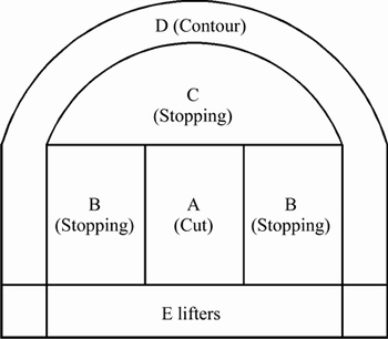
Figure 1 Tunnel sections [9-11]
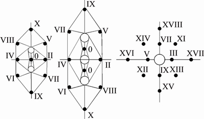
Figure 2 Three standard parallel hole cut methods proposed by NTNU [12]
2.2 Proposal for calculation of contour hole parameters
In each operation of designing smooth blasting passport, the determination of burden and charge concentration for contour blastholes is extremely important since it affects the smoothness of the tunnel boundary. OLOFSSON [10] proposed burden and charge concentration depending on explosive type and drillhole diameter, ZHANG [14] pointed out that the burden value may depend on many factors such as diameter of drillhole, decoupled charge, rock properties, explosive type, specific charge, wave attenuation, fragmentation, production and productivity [14].
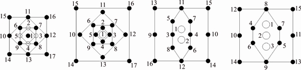
Figure 3 Parallel hole cut methods proposed by VOLVN model
From existence blast design models, the burden can be determined by the interaction of many factors. The burden value in the NTNU model depends on rock blastability, drillhole diameter hole length and tunnel cross-section. In the Swedish model, the burden depends on drillhole diameter, fixation factor, rock constant, explosive type and spacing/burden ratio [12]. The burden value in VOLVN model depends on:
1) Diameter of drillhole
Rock Protodyakonov coefficient, which is presented for rock properties and widely applied in China [15] and Vietnam [16], is determined from the uniaxial compressive strength of the rock as [17]:
f=��P/K (1)
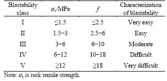
where f is the Protodyakonov coefficient of the rock; ��P is the rock��s uniaxial compressive strength in MPa; K is a constant equal to 10 MPa. The standard classification indexes for rock mass blastability in relation to rock Protodyakonov coefficient are resumed by LU [18] in Table 1.
Table 1 Classification standards of rock mass blastability [18]
3) Explosive type
4) Distance between cracks on tunnel face, which is presented for the fragmentation of rock and determined by measuring directly in situ.
5) Face advance of one tunneling cycle
Both values of burden and charge concentration can be determined by empirical method. LANGEFORS et al [19] proposed the results table from investigations and practices in Europe and the USA are shown in Table 2.
By using the graphic analysis method, it is recognized that the relation among burden, charge concentration and drillhole diameter is mostly linear as shown in Figure 4.
Table 2 LANGEFORS proposal of relation between burden, charge concentration and drillhole diameter
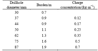
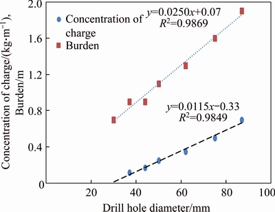
Figure 4 Relation between drillhole diameter with burden and charge concentration
According to NOGEL [20] who did a study using drillhole diameter of 36 mm and Ammonite No. 6 explosive substance, it is proposed that the burden (B, m) and charge concentration (q, kg/m) can be determined by distance between cracks on the tunnel face (dc, m) and Protodyakonov coefficient of the rock (f ) with following formulas [20]:
The burden:
B=0.9-0.25Kc (2)
where Kc is the relative cohesion coefficient, Kc=1 when dc>1, Kc=0.1+(dc-0.2) when 0.2��dc��1, and Kc=0 when dc<0.2.
The concentration of the charge:
Q=[0.4+Kc(0.58-0.032(67/f-1.7))]B (3)
The VOLVN was modeled relied upon the proposal of NOGEL [20] and LANGEFORS et al [19] to generate the following formulas:
B'=0.9-0.25Kc+0.0205(d-36) (4)
q'={[0.4+Kc(0.58-0.032(67/f-1.7))]B+0.0115(d-36)}(360/A) (5)
where 0.0205 is drillhole diameter correlation of burden achieved by function in Figure 4; d is drillhole diameter; 36 mm is drillhole diameter using NOGEL [20] research proposal; 0.0115 is drillhole diameter correlation of charge concentration achieved by function in Figure 4; 360 cm3 is lead bomb expansion achieved by using Ammonite No.6 explosive substance; A is explosive detonating pressure achieved by doing lead bomb expansion experiment (cm3).
2.3 Proposal for algorithm linking between Delphi programming language and AutoCAD
One of the main purposes of developing VOLVN model is creating a blasting model that can link calculation blasting result parameters and process of drawing blasting passport in AutoCAD. Using the model, the tunnel contour blasting passport in AutoCAD can be obtained automatically. There are several methods to draw automatically in AutoCAD, such as:
1) Using Script file.
2) Using DFX text files.
3) Using Lisp, Object ARX, and VBA programming languages.
Among those methods, using Script file method is simple because it is close to the manual drawing labor. These following steps are working procedure of the model:
1) Relying on specialized knowledge to calculate parameters of blastholes and blasting pattern.
2) Taking the AutoCAD origin coordinates (0, 0) as a base point to calculate coordinates of blastholes.
3) Combining the calculated coordinates of blastholes and the AutoCAD drawing commands to create a script file that allows drawing automatically blasting passport.
For example, drawing a semi-circular tunnel with a height of h and a width of B, VOLVN model must create a Script file with the following contents:
pline 0, h@0, -h@B, 0@0, h arc SB/2, (h+B/2) 0, h (6)
Hence, the interactive features and algorithms linking between Delphi programming language and Auto CAD were examined and developed. VOLVN model was designed to exporting a Script file that can be used to draw blasting passport in AutoCAD automatically.
2.4 Interface and working procedure of VOLVN model
VOLVN model was programmed by Delphi programming language, consisting of 8000 code lines and capability of running directly in all versions of Windows without installation. The working procedure of VOLVN model is presented by the following example which is one of the blasting passports created during the construction of DakMy3 hydropower project. The blasting conditions are as the following:
1) Tunnel section shape: semi-circular with 6.5 and 6.2 m in height and width, respectively.
2) Number of empty holes for parallel methods: one 102 mm diameter hole per each cut and 38 mm diameter for charged holes.
3) Explosive type: Ammonite AD1 with following characters: lead bomb expansion (detonating pressure) of 350��360 cm3, explosive speed 3.600��4.200 m/s, specific gravity of 950��1050 kg/m3.
4) The rock Protodyakonov coefficient f=7.
5) The distance between the cracks on the face is 0.7 m.
6) The face advance of one tunneling cycle is 3 m.
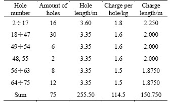
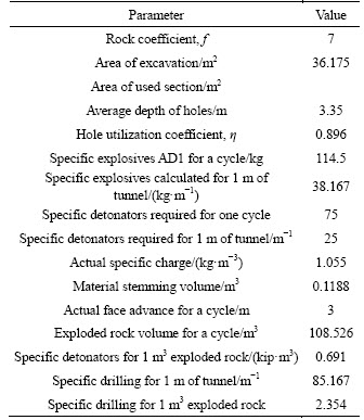
In the first windows, the introducing initial data are shown in Figure 5. The model will automatically calculate and update blasthole parameters. The results are shown in Table 3 and the economic-technical indices are shown in Table 4. Both tables can be saved as an Excel table file or printed directly.
The VOLVN model provides a script file when running with AutoCAD software, the blasting passport will be drawn automatically in seconds, the obtained passport is shown in Figure 6.
The VOLVN model was tested by One Member Limited Song Da 10.1 Company in the construction of DakMy3 hydropower project. The application of the model has produced good results, with the drillhole utilization coefficient up to 95%, the tunnel boundary was created very well and satisfied all of the investor requirements.
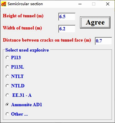
Figure 5 Introducing initial data
Table 3 Table of blasthole profiles
2.5 Comparison with other tunnel blast design models with an example
The comparison is achieved by introducing a similar input data as the blast design example realized with the NTNU model [9] and the Swedish model [12], the main input is as follows: tunnel area=19.5 m2, drillhole diameter=45 mm, drillhole length=3.2 m, empty hole diameter=102 mm, explosive type=cartridge explosive, explosive density=1200 kg/m3, rock constant=0.4.
Table 4 Table of economic-technical indices
The rock constant c=0.4 is assumed to be equivalent to the rock Protodyakonov coefficient f=10 and the cracks�� distance=0.7 m. The blasting result is shown in Table 5.
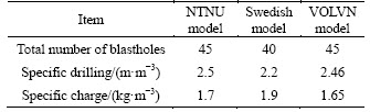
A comparison of total blast design result between NTNU model, Swedish model and VOLVN model is summarized in Table 6.
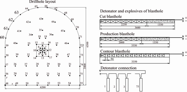
Figure 6 Blasting passport in AutoCAD (Length unit: mm)
Table 5 Blast design result realized by VOLVN model
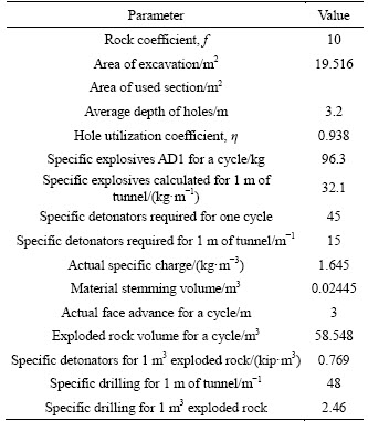
Table 6 Total blast design results
3 Results of investigation on contour blasting parameters by using VOLVN model
In order to investigate the relations among rock Protodyakonov coefficient, cracks�� distance and total blastholes number, specific charge with the variation of blasthole diameter and the tunnel area, the following input parameters are the same in all of the automatic calculated processes:
1) Tunnel section shape: semi-circular with a width/height ratio of 1.5;
2) Number of empty holes for parallel methods: one 102 mm hole per each cut;
3) Explosive type: Ammonite AD1 with the following characters: lead bomb expansion of (detonating pressure) 0.972 cm3, explosive speed of 0.857 m/s, specific gravity of 0.905 kg/m3.
4) The face advance of one tunneling cycle is 3 m.
3.1 Relation between rock Protodyakonov coefficient and specific charge
The relation between rock Protodyakonov coefficient (f) and specific charge (Sc) with the variation of tunnel area (A) was investigated by following procedures:
1) Varying the value of rock Protodyakonov coefficient and tunnel area;
2) Fixing diameter of charge drillhole: d=38 mm;
3) Fixing cracks�� distance value: dc=0.7 m.
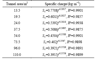
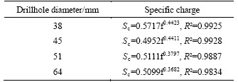
The calculated results are shown in Table 7 and Figure 7. The equations that present the relation between them are shown in Table 8.
The relation between rock Protodyakonov coefficient (f) and specific charge (Sc) with the variation of charged drillhole diameter (d) was investigated by following procedures:
1) Varying the value of rock Protodyakonov coefficient and charged drillhole diameter;
2) Fixing value of tunnel area: A=37.5 m2;
Table 7 Relation between rock coefficient (f) and specific charge (Sc) with variation of tunnel area
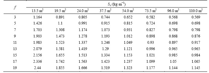
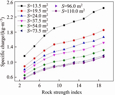
Figure 7 Relation between rock strength index and specific charge with variation of tunnel area
Table 8 Equations of relations between rock strength index and specific charge with variation of tunnel area
3) Fixing cracks�� distance value: dc=0.7 m.
The calculated results are shown in Table 9 and Figure 8. The equations that present the relation between them are shown in Table 10.
3.2 Relation between cracks�� distance and blasting result parameters
The effect of cracks�� distance (dc) on drillholes number (N) and specific charge (Sc) with the variation of tunnel area (A) was investigated by the following procedures:
1) Varying the value of cracks�� distance and tunnel area;
2) Fixing diameter of charge drillhole: d= 38 mm;
3) Fixing rock Protodyakonov coefficient value: f=7.
The calculated results are shown in Table 11, Figures 9 and 10. The equations that present the relation between them are shown in Table 12.
The effect of cracks�� distance (dc) on drillholes number (N) and specific charge (Sc) with the variation of charged drillhole diameter (d) was investigated by following procedures:
1) Varying the value of cracks�� distance and charged drillhole diameter;
2) Fixing value of tunnel area: A=37.5 m2;
3) Fixing rock coefficient value: f=7.
Table 9 Relation between rock coefficient and specific charge with variation of charged drillhole diameter
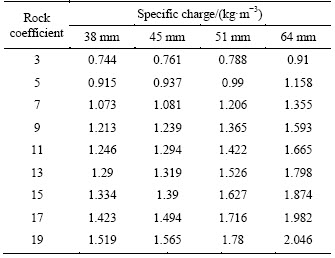
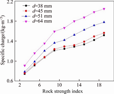
Figure 8 Relation between rock coefficient and specific charge with variation of charged drillhole diameter
Table 10 Equations of relations between f and Sc with variation of charged drillhole diameter
The calculated results are shown in Table 13, Figures 11 and 12. The equations that present the relation between them, are shown in Table 14.
Table 11 Relation between dc and N, dc and Sc with variation of tunnel area
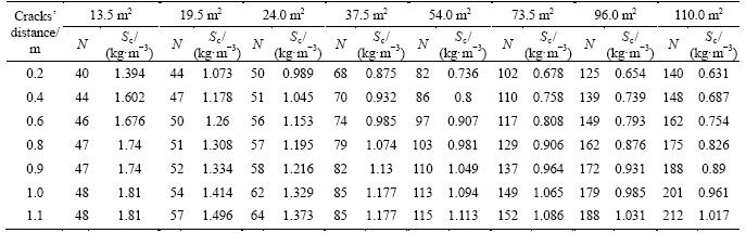
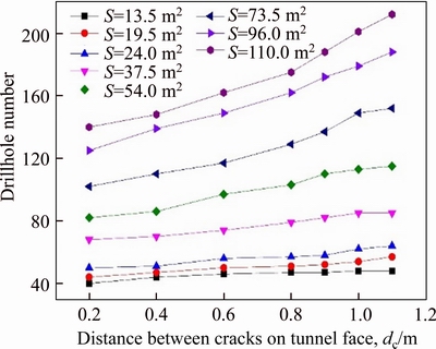
Figure 9 Relation between dc and N with variation of tunnel area
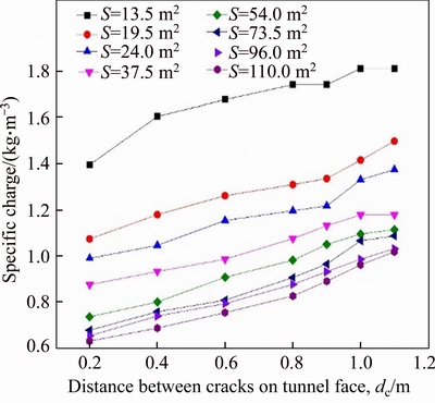
Figure 10 Relation between dc and Sc with variation of tunnel area
3.3 Relation between tunnel area and blasting result parameters
The effect of tunnel area on drillholes number and specific charge with the variation of charged drillhole diameter was investigated by the following procedures:
1) Varying the value of tunnel area and charged drillhole diameter;
2) Fixing cracks�� distance value: dc=0.7 m;
3) Fixing rock Protodyakonov coefficient value: f=7.
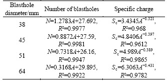
The calculated results are shown in Table 15, Figures 13 and 14. The equations that present the relation between them are shown in Table 16.
4 Analysis of results
All achieved results were investigated for tunnel contour blasting passport. Figures 7 and 8 show that specific charge increases as rock Protodyakonov coefficient increases. This increase can be divided into 2 segments: specific charge increases rapidly with rock blastability class I, II, III (f��9) and increases slowly with rock blastability class IV, V (f>9).
Figures 9 and 10 show that drillhole numbers and specific charge increase as distance between cracks on tunnel face increases in all tunnel area dimensions; Figure 9 shows that the line correlated with large area (A��54 m2) is more inclined than the line correlated with small area (A<54 m2). This means cracks�� distance is an important parameter to take in account of determining the number of drillhole on the tunnel face, especially for large tunnel area.
Figures 11 and 12 show that when the cracks�� distance increases, not only the drillhole numbers increase, but also the specific charge needs to increase too, especially for small charged drillhole diameters.
Figure 13 shows that the drillhole numbers increase almost linear in function with tunnel area.
Table 12 Equations of relation between dc and N, dc and Sc with variation of tunnel area
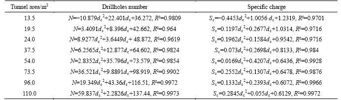
Table 13 Relation between dc and N, dc and Sc with the variation of charged drillhole diameter
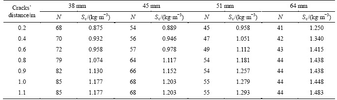
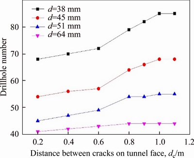
Figure 11 Relation between dc and N with variation of charged drillhole diameter
The number of blasthole with small diameter is found to be high. From technical point of view, the results show that it is better to use blastholes with larger diameter for bigger tunnel face areas.
Figure 14 shows that specific charge decreases as tunnel area increases, the specific charge is changing abruptly when A��54 m2, lightly when A>54 m2; and the specific charge value is almost merged at a point when A=110 m2. It means the specific charge value of very large tunnel does not depend on drillhole diameter parameter.
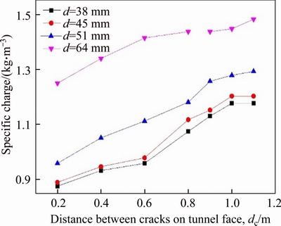
Figure 12 Relation between dc and Sc with variation of charged drillhole diameter
With the increase of drillhole diameter, the number of drillholes decreases (Figures 11 and 13) while specific charge increases (Figures 8, 12, and 14).
5 Discussion
This study has been provided with equations and graphs that can be used in primary blasting passport design. During analysis, some parameters are assumed to be constant. Semi-circular tunnel shape is chosen to investigate the relations between blasting parameters because it is a popular tunnel shape in situ. This relation should have a modification coefficient adequate with tunnel shape. One empty hole of 102 mm diameter is selected for the parallel hole cut method in all calculation process. So, it should be clarified that if another parallel hole cut method is used, the value of drillhole numbers and specific drilling should have a little modification. If explosive detonating pressure increases, the burden also increases. The value of drillhole numbers and specific charges thus will decrease. Consequently, in blasting practice need to multiply research results with an explosive detonating pressure coefficient.
Table 14 Equations of relation between dc and N, dc and Sc with variation of charged drillhole diameter
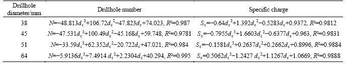
Table 15 Relations between A and N, A and Sc with variation of charged drillhole diameter
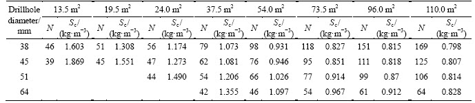
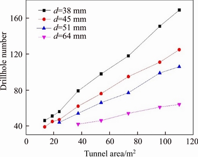
Figure 13 Relations between A and N with variation of charged drillhole diameter
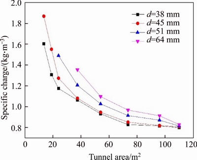
Figure 14 Relations between A and Sc with variation of charged drillhole diameter
Table 16 Equations of relations between A and N, A and Sc with variation of charged drillhole diameter
6 Conclusions
Model VOLVN for tunnel contour blasting passport design was developed to help in completing an automated closed cycle from calculating parameters to design blasting passport in AutoCAD. The VOLVN model can be used to analyze the effect and the sensitiveness of rock Protodyakonov coefficient, distance between cracks on the tunnel face, blasthole diameter and tunnel area on blasting results. Outcomes of the investigations can meet the essential factors such as required specific charge and drillhole number for a blasting design.
The results of the analysis show that specific charge increases as rock Protodyakonov coefficient and cracks�� distance increase but specific charge decreases when tunnel face area increases. Moreover, the number of holes increases linearly as tunnel face area increases. The findings demonstrate that with increasing drillhole diameter, the number of drillholes decreases while specific charge increases.
This research provides a deep investigation about relation between principal blasting conditions with blasting result parameters in some secondary fixed conditions such as tunnel shape, parallel hole cut method and explosive substance. The model results thus need to be modified the coefficient to achieve optimum blasting pattern in blasting practice.
Contributors
CAO Ping provided the concept and edited the paper. Nguyen Ngoc MINH designed the study, conducted the literature review, wrote and edited the paper. LIU Zhi-zhen edited the paper.
Conflict of interest
CAO Ping, Nguyen Ngoc MINH and LIU Zhi-zhen declare that they have no conflict of interest.
References
[1] VERMA H K, SAMADHIYA N K, SINGH M, GOEL R K, SINGH P K. Blast induced rock mass damage around tunnels [J]. Tunnelling and Underground Space Technology, 2017, 71: 149-158. DOI: 10.1016/j.tust.2017.08.019.
[2] MISHRA A K, GUPTA R N. Rapid excavation of tunnels using innovative drilling and blasting techniques [C]// The 10th International Symposium on Rock Fragmentation by Blasting. London: Taylor & Francis Group, 2013: 15-22.
[3] HU Ying-guo, LU Wen-bo, CHEN Ming, YAN Peng, YANG Jian-hua. Comparison of blast-induced damage between presplit and smooth blasting of high rock slope [J]. Rock Mechanics and Rock Engineering, 2014, 47(4): 1307-1320. DOI: 10. 1007/s00603-013-0475-7.
[4] LIU Kai-yun, LIU Bao-guo. Optimization of smooth blasting parameters for mountain tunnel construction with specified control indices based on a GA and ISVR coupling algorithm [J]. Tunnelling and Underground Space Technology, 2017, 70: 363-374. DOI:10.1016/j.tust.2017. 09.007.
[5] MAN Ke, LIU Xiao, WANG Ju, WANG Xi-yong. Blasting energy analysis of the different cutting methods [J]. Shock and Vibration, 2018, 2018: 9419018. DOI: 10.1155/2018/ 9419018.
[6] XIE L X, LU W B, ZHANG Q B, JIANG Q H, WANG G H, ZHAO J. Damage evolution mechanisms of rock in deep tunnels induced by cut blasting [J]. Tunnelling and Underground Space Technology, 2016, 58: 257-270. DOI: 10.1016/j.tust. 2016.06.004.
[7] SOROUSH K, MEHDI Y, ARASH E. Trend analysis and comparison of basic parameters for tunnel blast design models [J]. International Journal of Mining Science and Technology, 2015, 25(4): 595-599. DOI: 10.1016/j.ijmst. 2015.05.012.
[8] BERTA G. Explosives: An engineering tool [J]. Italesplosive, 1990, 6: 452-460.
[9] Charge calculations for tunnelling [M]// Underground Mining Methods Handbook. New York: Society of Mining Engineers, 1982.
[10] OLOFSSON S O. Applied explosives technology for construction and mining [M]. ARLA, Sweden: APPLEX (Applied Explosives Technology), 1990.
[11] ZHOU Chuan-bo, WANG peng, LEI Yong-jian, YIN Xiao-peng. Optimization on cut-hole of mining tunnel excavation [J]. Mining Science and Technology, 2009, 19(1): 70-73. DOI: 10.1016/ S1674-5264(09)60013-2.
[12] ZARE S, BRULAND A. Comparison of tunnel blast design models [J]. Tunnelling and Underground Space Technology, 2006, 21(5): 533-541. DOI: 10.1016/j.tust.2005.09.001.
[13] JIMERO C L, JIMERO E L, CARCEDO F J A. Drilling and blasting of rocks [M]. London: Taylor& Francis Group, 1995.
[14] ZHANG Zong-xian. Rock fracture and blasting theory and applications [M]. Oxford: Butterworth-Heinemann, 2016. DOI: 10.1016/b978-0-12-802688 -5.00003-8.
[15] XIAO Shuang-shuang, LI Ke-min, DING Xiao-hua, LIU Tong. Rock mass blastability classification using fuzzy pattern recognition and the combination weight method [J]. Mathematical Problems in Engineering, 2015: 724619. DOI: 10.1155/2015/724619.
[16] NGUYEN H, BUI X N, TRAN Q H, LE T Q, DO N H, LE T T H. Evaluating and predicting blast-induced ground vibration in open-cast mine using ANN: A case study in Vietnam [J]. SN Applied Sciences, 2019, 1(1): 125. DOI: 10.1007/s42452-018 -0136-2.
[17] PROTODYAKONOV M. Mechanical properties and drillability of rocks [C]// Proceedings of the Fifth Symposium on Rock Mechanics. US: Symposium Publication division, 1962: 103-118.
[18] LU P. The characterisation and analysis of in-situ and blasted block size distribution and the blastability of rock masses [D]. London: University of London, 1997.
[19] LANGEFORS U, KIHLSTROM B. The modern technique of rock blasting [M]. Stockholm: Almqvist & Wiksell Forlag AB, 1978.
[20] NOGEL J O. Rock fragmentation with explosives [M]. La Habana: Felix Varela, 1998. (in Spanish)
(Edited by FANG Jing-hua)
���ĵ���
���������������ģ�͵Ĺ��汬�Ʋ���
ժҪ�����汬��Ч���߶������ڿ�ֱ������ʯ����ϵ���������������϶����������֮��ļ��ȳ�ʼ���Ʋ������������һ���ܹ�ʵ��Delphi����������AutoCAD�Խӵ��㷨������������㷨������һ�������������ģ�͡��������������ģ���ܹ�ʵ����AutoCADΪƽ̨���������汬���Զ���ơ����ڿ�ֱ������������仯�������£��о�����ʯ����ϵ������϶�����ڿ������͵�λըҩ��������Ӱ�죬������һ��߶���ط��̡��о������������λըҩ������������ʯ����ϵ������϶�����ڿ�ֱ�������Ӷ����ӣ�����������������������Ӷ���С�����⣬�ڿ�����������������������ӳ��������ӣ����������ڿ�ֱ�����������С��
�ؼ��ʣ����汬�ƣ�����ģ�ͣ�������ƣ���������
Received date: 2020-03-23; Accepted date: 2020-06-12
Corresponding author: CAO Ping, PhD, Professor; Tel: +86-13973128263; E-mail: pcao_csu@sina.com; ORCID: https://orcid.org/ 0000-0003-3192-0267
Abstract: The quality of contour blasting depends on many initial blasting parameters. The parameters including blasthole diameter, rock Protodyakonov coefficient, tunnel area and distance between cracks on the tunnel face are more important. In this study, an algorithm linking between Delphi programming language and AutoCAD was created to develop a tunnel blasting model. Using this model, tunnel contour blasting passport in AutoCAD can be obtained automatically. The effects of rock Protodyakonov coefficient and cracks�� distance on blastholes number and specific charge with the variation of blasthole diameter and the semi-circular tunnel face area were investigated to yield a set of equations with the highest correlations. The results show that specific charge increases as rock Protodyakonov coefficient, cracks�� distance and drillhole diameter increase, but decreases when tunnel face area increases. In addition, the number of drillholes increases linearly as tunnel face area increases but decreases when drillhole diameter increases.
