

ARTICLE
J. Cent. South Univ. (2019) 26: 2077-2087
DOI: https://doi.org/10.1007/s11771-019-4155-y

Parametric study of natural convection over horizontal annular finned tube
H. NEMATI1, M. MORADAGHAY2
1. Department of Mechanics, Marvdasht Branch, Islamic Azad University, Marvdasht, Iran;
2. Department of Mechanics, Shiraz Branch, Islamic Azad University, Shiraz, Iran
 Central South University Press and Springer-Verlag GmbH Germany, part of Springer Nature 2019
Abstract:
Natural convection heat transfer from annular finned tubes was studied numerically. Effects of fin spacing, temperature difference and tube diameter on flow pathlines and local heat transfer were also studied. It was shown that pathlines remain mostly circular for different geometries. Moreover, the contributions of fin periphery, fin side and bare tube to heat transfer were specified. It was shown that the heat transfer per unit area of fin periphery can be several times that of other parts. Moreover, in higher finspacing, the heat transfer from the bare tube can be more important than fin sides.
Key words:
natural convection; fin spacing; parametric study; annular finned tube��
Cite this article as:
H. NEMATI, M. MORADAGHAY. Parametric study of natural convection over horizontal annular finned tube [J]. Journal of Central South University, 2019, 26(8): 2077-2087.
DOI:https://dx.doi.org/https://doi.org/10.1007/s11771-019-4155-y1 Introduction
Natural convection heat transfer is used widely in different types of equipment, such as electronic equipment, especially in conjugated with nano fluids [1-3] or phase change materials [4]. However, natural convection by itself is not strong enough [5, 6] and therefore, using extended surfaces or fins is mandatory. Study of natural convection from extended surfaces returns back to experimental works of ELENBAAS [7] on vertical parallel plates. He proposed a modification to Rayleigh number by multiplying it by the ratio of plate spacing to plate length. EDWARDS et al [8] later used his method to study heat transfer from cylindrical disk extended surfaces. Other works may be referred to for more information in this regard [9-17]. However, based on the best knowledge of authors, nothing may be found in the literature concerning to specify the contribution of fin periphery, fin side and bare tube to heat transfer. Because determining local heat transfer in finned tube especially for natural convection is really laborious and somehow inaccurate. So, it is not surprising that all experimental works are contented to theoverall heat transfer coefficient. Therefore, the importance of fin periphery, fin side and bare tube in natural convection heat transfer is not clear yet. The only work on local heat transfer returns back to SPARROW et al [11]. They used naphthalene sublimation technique to study the local heat transfer from the horizontal tube with square fins. They concluded that the active zones of natural convection heat transfer in a fin-tube system are confined to the peripheral regions of the fin surface, and that the inner portions of the fin do not contribute significantly to the heat transfer. It is necessary to mention that in their experiment, the heat transfer from the bare tube was not included and only the heat transfer from fin sides and its periphery was studied.
Another ambiguity in natural convection from the finned tube is the effect of tube presence on flow path and heat transfer. Most of the works in this filed are based on heat transfer from parallel plats or disks and because no flow visualization is performed, it is not clear if pathlines remain mostly parallel and are more similar to flow between series of parallel plats or, they are circular and similar to pathlines of flow around the tube.
Numerical method is a powerful tool for flow visualization. It may be very difficult or even in some special cases, impossible to have flow pattern by experimental methods. However, by numerical methods, flow pattern easily is in hand. For parallel plates or disks, it can be assumed that air flows in vertical parallel paths from down to up. However, it is clear that for the finned tube, the effect of the tube on flow pattern cannot be ignored. In the following, flow patterns in various temperature differences, fin spacing and tube diameter have been presented and studied. Moreover, the determination of the local heat transfer over different parts of the finned tube as well as their contributions is another facility offered by CFD methods. More importantly, CFD technique obviates the need to make the correction for extraneous heat loses due to radiation because each phenomenon can be simulated separately and independently.
In the present study, near seventy different cases have been simulated to find out pathlines of air in circular finned tubes with various geometries.
Moreover, it is tried to specify the importance of each part of a finned tube in heat transfer under different working condition.
2 Numerical method and assumption
The simulating geometry is shown in Figure 1. In this figure, all dash lines indicate symmetry boundary condition for which the gradients of all pressure and temperature normal to boundaries as well as normal velocity components are zero. Other exterior surfaces are assumed opening for which P=Patm, T=T��.
At the solid-fluid interface, the continuity of temperature as well as continuity of heat flux is held:
 ,
,  (1)
(1)
for the rest of doming, the governing equations are as follows. The fluid flow regime is assumed as laminar.
Continuity:
 (2)
(2)
Momentum equation:
 (3)
(3)
 (4)
(4)

Figure 1 Simulating geometry:
 (5)
(5)
Energy equation in the fluid zone:
 (6)
(6)
and energy equation in the solid zone:
 (7)
(7)
Coolant fluid is assumed dry air for which:
 (8)
(8)
and finally, the Nusselt number based on fin spacing, S:
 (9)
(9)
in which, the convective heat transfer coefficient, h, is calculated by
 (10)
(10)
where  is the average fin-tube temperature which can be presented by:
 (11)
(11)
where Ab and Af is bare tube area and fin area, respectively. It is clear that:
 (12)
(12)
Fin efficiency, �� in Eq. (11) is:
 (13)
(13)
and Qmax occurs when the fin surface transfers heat at bare tube temperature, Tw.
 (14)
(14)
However, for an annular fin, the efficiency may be approximated by [18]:
 (15)
(15)
 (16)
(16)
 (17)
(17)
in which ks and tf are fin thermal conductivity and fin thickness, respectively.
The buoyancy-driven steady-state laminar fluid flow was simulated using the CFX solver, ANSYS 18.0 which utilizes element-based finite volume method [19]. ANSYS CFX uses the strategy proposed by RHIE et al [20] as the discretization method for the mass flows to avoid the decoupling of the pressure field. Moreover, the high-resolution scheme used for advection terms. RMS-residual target was set to 10-4 and all other settings left unchanged.
Structured mesh with ��O�� topology was used to discretize the domain. A sample of grid arrangement over the cross-section of the computational domain is shown in Figure 1(c). Grids in this topology are closer to each other at the peripheral of tube and fins are courser in far. A deep grid study was performed to ensure the accuracy of the results. It ended to the number of elements more than 1.6��106. A sample of grid study has been shown in Table 1 and its specifications of geometry are listed in Table 2.
Table 1 Results of grid independence study
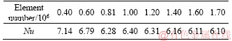
Table 2 Geometry used for grid independence study

Domain independence was checked also. Results have been presented in Table 3 and the geometrical parameters used for this test have been reported in Table 4. Based on these results, a minimum of five times the fin diameter is acceptable for the present simulation.
In the present study, near seventy different cases were simulated. The ranges of parameters used in the simulation have been presented in Table 5. These cases were selected randomly.
Table 3 Results of domain independence study
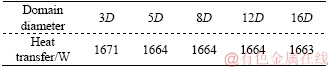
Table 4 Geometry used for domain independence study
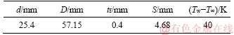
Table 5 Range of simulated parameters

However, it was tried to have a uniform distribution all over the ranges.
3 Data validation
To validate the results, first of all, the described method was applied to a bare cylinder without any fin to simulate the natural convection around a long cylinder. Results are presented in Table 6 and also compared with two well-known experimental correlations of CHURCHILL et al [21] and MORGAN [22]. Results of these comparisons seem satisfactory.
Table 6 Comparison between present study and experimental correlations

The references correlations are presented in the following:
CHURCHILL et al [21]:
 , Rad<1012 (18)
MORGAN [22]:
 (19)
(19)
Secondly, the results were compared with the experimental correlation of TSUBOUCHI et al [10] for a horizontal cylinder with high fins (D/d>1.67) and numerical correlation of SENAPATI et al [23] for 5<>8.
TSUBOUCHI et al [10]:
 ,
,
for 3��Ra��104 (20)
where 

 .
.
SENAPATI et al [23]:
 , 5��RA��108(21)
where c0=-3.827, c1=0.047, c2=1.039, c3=2.548, a0=0.348, a1=-0.173, a2=0.175, a3=-0.009.
Figure 2 illustrates these comparisons. Based on Figure 2(a), the results show better agreement with numerical correlation in comparison to experimental correlation by TSUBOUCHI et al [10]. The acceptability of this slight deviation may be vindicated by the fact that TSUBOUCHI et al [10] excluded heat transfer from fin tip and presented a separate Nusselt number for fin tip heat transfer as presented in Eq.(22).
(22)
For this reason, in the next step, heat transfers from the fins tips were excluded and calculated; Nusselt numbers were compared again in Figure 2(b). A very good agreement was observed this time.
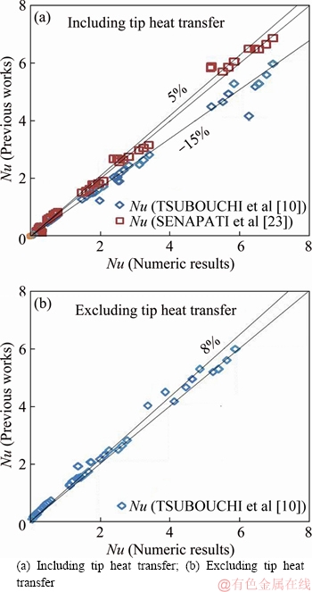
Figure 2 Comparison with previous correlations:
4 Results and discussions
Three main parameters can affect the flow field and heat transfer from a finned tube, i.e. tube diameter, temperature difference, and fin spacing. In the following, effects of these parameters on the flow field and heat transfer are studied deeply and moreover, the contributions of each fin part (fin peripheral, fin side, and bare tube) to heat transfer are specified. The combination of all the aforementioned parameters may be presented in Elenbaas number. Elenbaas number is, in fact, the Rayleigh number multiplied by channel spacing to channel length. At last, the heat transfer contributions of different fin parts as a function of Elenbaas number are investigated.
4.1 Variation of temperature differences and fin spacing
Variations of heat transfer per unit area of fin tip, fin side and bare tube have been shown in Figure 3. It must be emphasized that heat flux is proportional to the heat transfer coefficient. Based on this figure, the fin tip heat flux is much more than other parts of the finned tube. Since fin tip accesses more to fresh air than other parts, it can be observed that bare tube has the lowest heat flux in this group.
Assuming a long cylinder with a diameter equal to fin diameter as well as a long cylinder with a diameter equal to tube diameter, the heat fluxes have been calculated by means of Eq. (22). These heat fluxes have been shown in Figure 3(a) as ��Ideal fin�� and ��Ideal tube�� respectively. Comparing the ��Ideal tube�� heat flux with bare tube shows that heat transfer from the bare tube is less than its equivalent long cylinder. It will be shown later that the fin boundary layer affects the tube boundary layer and causes a considerable reduction in heat transfer. As the fin spacing increases, boundary layers decrease and heat transfer from bare tube increases. It is expected that at a very large fin spacing, heat transfer from bare tube reaches to its ideal case, i.e. a long horizontal cylinder.

Figure 3 Heat flux per unit area (a) and percent of heat transfer (b) for different fin parts(d=25.4 mm, D=57.15 mm, tf=0.4 mm)
For the fin tip, the manner is even more complicated. Heat transfer from fin tip is much more than its equivalent horizontal cylinder and it is more similar to mixed convection. The reason is that the air sucked into the fin spacing or on the upper side, the raising plum from the channel created by fin spacing has a considerable velocity which causes an excellent cooling effect on the fin tip. It will be shown also that by increasing the fin spacing, this velocity and consequently heat flux increases. However, since the heat transfer from other fin parts increases also, the effective temperature difference between the air stream and fin tip decreases. This reduction in temperature differences is clear in fin temperature contour (Figure 4). Therefore, the heat transfer per unit area decreases slightly.
In this study, fin thickness was assumed constant and was equal to 0.4 mm and areas of fin parts are different. According to Figure 3(b), between 70% and 90% heat is transferred from fin side. In smaller fin spacing, the role of fin tip is prominent and in larger fin spacing, the bare tube gets more dominant in comparisons to fin tip. The same conclusions are valid for ��T=80 ��C. Therefore, their graphs have been omitted for sake of brevity.
Velocity vectors over the bare tube as well as temperature contour over fin surface have been shown in Figure 4 for extreme conditions. Temperature contours show that the coolest part is located at the fin lower surface which is in contact with fresh and cold air. Comparing Figures 4(a) and (b) to understand the temperature difference effect reveals that the temperature difference does not affect the contour pattern. Moreover, it can be observed that in Figures 4(c) and (d) with larger fin spacing, constant temperature lines remain more circular. This shows that in larger fin spacing, the convective heat transfer coefficient remains more uniformly. On the other hand, since in larger fin spacing, the more area is at the cooler temperature, it is expected that the fin efficiency deviates more form unity. In all cases, velocity vectors preserve their circular patterns around the tube. However, the quiescent area in larger fin spacing is slender and therefore, the rising plume is thicker.
Figure 5 shows temperature contour on a cross-section of the finned tube and its surrounding at different fin spacing. As it is clear at small fin spacing (S=3.22 mm), the temperature contours are completely uniform. However, in larger fin spacing (S=8.07 mm), a small deviation in temperature can be observed, which is due to poor air thermal conductivity. Temperatures on both sides are slightly more than the temperature in the fluid core. At large fin spacing (S=25.24 mm) a secondary phenomenon occurs. Another plume rises from the tube at the middle of fin spacing. So, a secondary peak in temperature may be observed. To investigate the effect of fin spacing more quantitatively, three horizontal lines (HL1-3) are considered. Horizontal line HL1 is considered at the middle of fin length i.e.  Another one is considered at the fin edge at which fluid exits and the last one is considered at the one fin length above fin tip. The velocity and temperature variations have been studied on these selected lines.
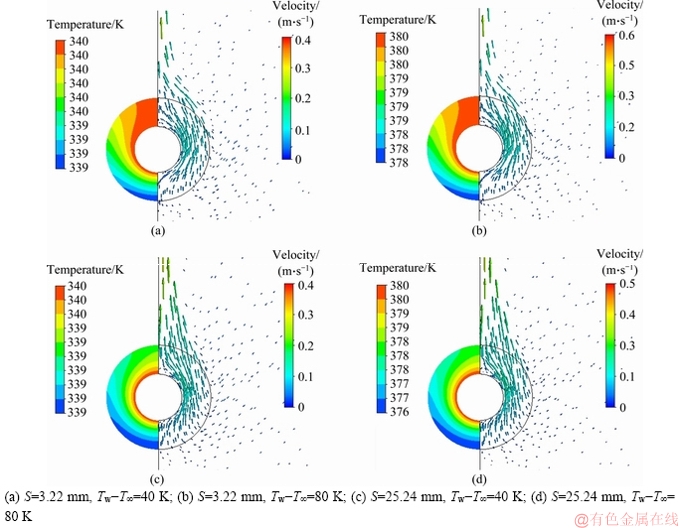
Figure 4 Fin temperature contour (left) and velocity vector over tube (right)(d=25.4 mm, D=57.15 mm, tf=0.4 mm):
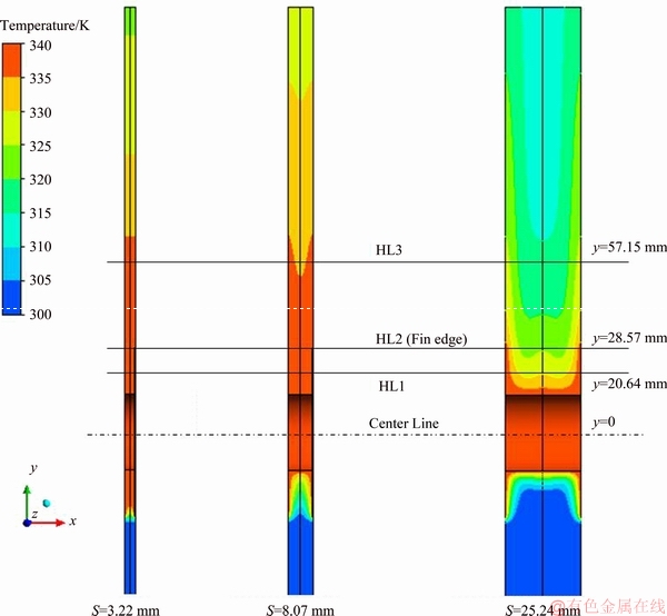
Figure 5 Temperature contour on finned tube and its surrounding cross section at different sin spacing: d=25.4 mm, D=57.15 mm, tf=0.4 mm, ��T=40��C
Based on Figure 6, for HL1 and HL2, fully developed internal flow behavior for very small fin spacing (S=3.22 mm) is considered which is expected. For larger fin spacing (S=8.07 mm), the velocity peak gets flatten which shows deviation from fully developed behavior. However, flow behavior is still similar to internal flow. In a large fin spacing (S=25.4 mm), the velocity profile is similar to a natural convection flow over a vertical plate.
Scrutinizing the velocity profile on HL1 and HL for S=25.24 mm reveals that there is a small peak in velocity in the middle of these lines. This proves the existence of a separate boundary layer over the tube is interfered by the fin walls boundary layers. The same results may be concluded, considering temperature profiles. Since the temperature profiles on selected horizontal lines for narrow fin spacing were approximately constant, it was not presented in Figure 7, for S=3.22 mm.
4.2 Tube diameter
Variations of heat transfer per unit area of fin tip, fin side and bare tube against tube diameter for a specified set of geometry have been shown in Figure 8. In this geometry group, S=3.22 mm for which, the flow was similar to fully developed internal flow.��Ideal tube�� and ��Ideal fin�� have been included also for comparison. Based on Figure 8, in narrow fin spacing, the contribution of the bare tube to heat transfer decreases by increasing the tube diameter; however, the fin side contribution increases. Since, in larger tube diameter, the total flow path length (that is proportional to fin length) decreases and therefore the boundary layer thickness decreases as well.

Figure 6 Fin velocity profiles under d=25.4 mm, D=57.15 mm, tf=0.4 mm, ��T=40��C
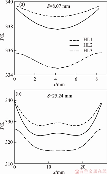
Figure 7 Fin temperature profiles under d=25.4 mm, D=57.15 mm, tf=0.4 mm, ��T=40��C
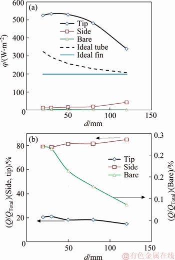
Figure 8 Heat flux per unit area (a) and percent of heat transfer (b) for different fin parts under D=70.10 mm, tf=0.4 mm, S=3.22 mm, ��T=40��C
Moreover, the fin efficiency increases also, which shows that the effective mean temperature difference is higher.
Velocity vectors over the bare tube as well as temperature contour over fin surface have been shown in Figure 9 for extreme conditions. The flow path in the smaller fin length (Figure 9(b)) remains more circular in comparison to the longer fin length (Figure 9(a)). So, the rising plume is thinner for smaller fin lengths.
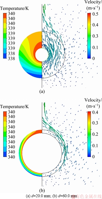
Figure 9 Fin temperature contour (left) and velocity vector over tube (right) under D=70.10 mm, tf=0.4 mm, S=3.22 mm, ��T=40��C:
4.3 Elenbaas number
As a final discussion, the contributions of different fin parts to heat transfer for all results have been plotted against Elenbaas number in Figure 10. Elenbaas number for an annular extended surface is defined as:
 (23)
(23)
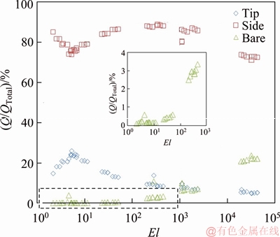
Figure 10 Percent of heat transfer for different fin parts
in which the term D+d is presented for average diameter (It is two times the average diameter;
however, the constant 2, in  is omitted for simplicity). Elenbaas number is a good index in an extended surface to show how far the flow is from fully develops behavior. Based on this figure, for El<6, the trend of data points is different and approximately linear. This El is related to fins for which the flow is similar to fully developed internal flow. For El more than 300, the heat transfer from bare tube increases more rapidly while the heat transfer from the fin side decreases. This El is related to the regain in which the rising boundary layer from the bare tube finds its relative independence. The heat transfer from fin tip for El>6 decreases monotonically.
5 Conclusions
In the present study, laminar free convection heat transfer from annular finned tubes was numerically studied. Effects of temperature difference, fin spacing as well as tube diameter on local heat transfer and flow pathlines were studied. To do this, around seventy different cases were simulated in wide ranges of tube diameter, fin diameter, and fin spacing. Results may be summarized in the following notes:
1) Flow field visualization shows that air pathlines are mostly circular around the tubeand not straight. So, it is more similar to pathlines around a tube.
2) Boundary layers on fin sides reduce the heat transfer from the bare tube significantly.
3) The most contribution to natural heat transfer is devoted to fin periphery. Fin periphery heat transfer coefficient is even more than an equivalent tube with the same diameter and the same temperature difference.
4) According to fin temperature contour, the lower part of a fin is colder than its upper part which shows that the heat transfer in the lower part of a finned tube is superior over its upper part.
5) Based on Elenbaas number, three different conditions can be observed: a) El<6 for which the flow is fully developed, b) El<300 for which the flow between two adjacent fins is developing and the tube and fin boundary layers interfering and c) El>300 for which tube boundary layer finds its relative independence.
Nomenclature
A=Af+Ab
Finned tube heat transfer area per unit length of tube, m2
Af
Fin surface area per unit length of tube, m2
Ab
Bare tube heat transfer area per unit length of tube, m2
D
Fin diameter, m
d
Tube outer diameter, m
h
Average convective heat transfer coefficient, W/(m2��k)
k
Fluid thermal conductivity, W/(m��K)
ks
Fin thermal conductivity, W/(m��K)
Nu
Nusselt number
P
Pressure, Pa
Q
Total heat transfer, W
S
Fin spacing, m

Average fin surface temperature, K
Tw
Fin surface temperature, K
tf
Fin thickness, m
��
Fin efficiency
��
Viscosity, Pa��s
��
Air density, kg/m3
References
[1] MAHMOODI M, KANDELOUSI S. Kerosene-alumina nanofluid flow and heat transfer for cooling application [J]. Journal of Central South University, 2016, 23: 983-990.
[2] DOGONCHI A, CHAMKHA A J, HASHEMI-TILEHNOEE M, SEYYEDI S, GANJI D. Effects of homogeneous- heterogeneous reactions and thermal radiation on magneto- hydrodynamic Cu-water nanofluid flow over an expanding flat plate with non-uniform heat source [J]. Journal of Central South University, 2019, 26: 1161-1171.
[3] MALEKI H, ALSARRAF J, MOGHANIZADEH A, HAJABDOLLAHI H, SAFAEI M R. Heat transfer and nanofluid flow over a porous plate with radiation and slip boundary conditions [J]. Journal of Central South University, 2019, 26: 1099-1115.
[4] LIU F H, XU J X, WANG��H��T, WANG H. Numerical method and model for calculating thermal storage time for an annular tube with phase change material��[J]. Journal of Central South University, 2017, 24: 217-226.
[5] BEJAN A. Convection heat transfer [M]. Hoboken, New Jersey: John Wiley & Sons, 2013.
[6] KREITH F, MANGLIK R M, BOHN M S. Principles of heat transfer, Cengage learning [M]. Stamford, USA: 2012.
[7] ELENBAAS W. Heat dissipation of parallel plates by free convection [J]. Physica, 1942, 9: 1-28.
[8] EDWARDS J, CHADDOCK J. An experimental investigation of the radiation and free convection heat transfer from a cylindrical disk extended surface [J]. Trans Am Soc Heat Refrig Air-Cond Eng, 1963, 69: 313-322.
[9] KNUDSEN J, PAN R. Natural convection heat transfer from transverse finned tubes [J]. Chem Eng Progr, 1963, 59: 44-49.
[10] TSUBOUCHI T, MASUDA H. Natural convection heat transfer from horizontal cylinders with circular fins [C]// International Heat Transfer Conference. Vol. IV. Elsevier Publishing Co., 1970.
[11] SPARROW E, BAHRAMI P. Experiments on natural convection heat transfer on the fins of a finned horizontal tube, International [J]. Journal of Heat and Mass Transfer, 1980, 23: 1555-1560.
[12] KAYANSAYAN N, KARABACAK R. Natural convection heat transfer coefficients for a horizontal cylinder with vertically attached circular fins [J]. Heat Recovery Systems and CHP, 1992, 12: 457-468.
[13] HAHNE E, ZHU D. Natural convection heat transfer on finned tubes in air [J]. International Journal of Heat and Mass Transfer, 1994, 37: 59-63.
[14] GUVEN A, YUNCU H. An experimental investigation on performance of fins on a horizontal base in free convection heat transfer [J]. Heat and Mass transfer, 2001, 37: 409-416.
[15] WANG C S, YOVANOVICH M, CULHAM��J. Modeling natural convection from horizontal isothermal annular heat sinks [J]. Journal of Electronic Packaging, 1999, 121: 44-49.
[16] AZIZ A, FANG T. Thermal analysis of an annular fin with (a) simultaneously imposed base temperature and base heat flux and (b) fixed base and tip temperatures [J]. Energy Conversion and Management, 2011, 52: 2467-2478.
[17] YAGHOUBI M, MAHDAVI M. An investigation of natural convection heat transfer from a horizontal cooled finned tube [J]. Experimental Heat Transfer, 2013, 26: 343-359.
[18] NEMATI H, SAMIVAND S. Simple correlation to evaluate efficiency of annular elliptical fin circumscribing circular tube [J]. Arabian Journal for Science and Engineering, 2014, 39: 9181-9186.
[19] ANSYS C. Release 18.0-User manual [M]. Canonsburg, PA, USA, 2018.
[20] RHIE C, CHOW W L. Numerical study of the turbulent flow past an airfoil with trailing edge separation [J]. AIAA Journal, 1983, 21: 1525-1532.
[21] CHURCHILL S W, CHU H H. Correlating equations for laminar and turbulent free convection from a vertical plate [J]. International Journal of Heat and Mass Transfer, 1975, 18: 1323-1329.
[22] MORGAN V T. The overall convective heat transfer from smooth circular cylinders [M]// Advances in Heat Transfer. Vol. 11. Elsevier, 1975: 199-264.
[23] SENAPATI J R, DASH S K, ROY S. Numerical investigation of natural convection heat transfer over annular finned horizontal cylinder [J]. International Journal of Heat and Mass Transfer, 2016, 96: 330-345.
(Edited by YANG Hua)
���ĵ���
ˮƽ���γ�Ƭ�ܵ���Ȼ���������о�
ժҪ���Ի��γ�Ƭ���ڵ���Ȼ�������Ƚ�������ֵ�о����о��˳�Ƭ��ࡢ�²�ܾ�������·���;ֲ����ȵ�Ӱ�졣������������ڲ�ͬ�ļ�����״��PathLines��������Բ�εġ����⣬����ȷ�˳�Ƭ�ܱߡ���Ƭ�����ܶԴ��ȵĹ��ס���Ƭ�ܱߵ�λ����Ĵ��ȿ�����������������������⣬�ڽϴ�ij�Ƭ����У�������ܵ��ȴ��ݱ�ɢ��Ƭ����Ҫ��
�ؼ��ʣ���Ȼ��������Ƭ��ࣻ�������о������γ�Ƭ��
Received date: 2019-05-06; Accepted date: 2019-07-05
Corresponding author: H. NEMATI, PhD, Assistant Professor; E-mail: H.nemati@miau.ac.ir; ORCID: 0000-0002-3896-0774
Abstract: Natural convection heat transfer from annular finned tubes was studied numerically. Effects of fin spacing, temperature difference and tube diameter on flow pathlines and local heat transfer were also studied. It was shown that pathlines remain mostly circular for different geometries. Moreover, the contributions of fin periphery, fin side and bare tube to heat transfer were specified. It was shown that the heat transfer per unit area of fin periphery can be several times that of other parts. Moreover, in higher finspacing, the heat transfer from the bare tube can be more important than fin sides.
